
Abstract
The growing increase in length of super and megayachts has driven structural designers to adopt longitudinal layouts as a main point in the structural scantlings. By the way, the optimization of weights, strength, deformations and dynamic behaviour has to be evaluated separately for each new unit because of the particular and unique characteristics of each vessel.
For this evaluation, especially for what the dynamic behaviour of ribbed plates is concerned, the use of numerical software based on the Finite Element Method is widely used since the early design stages in order to highlight benefits and weaknesses of a particular structural design.
In this paper, two different structural layouts of megayacht decks have been studied and tested by using a FE software: the first one has been created with longitudinal and transversal stiffeners with the same cross section. In the second layout, transversal stiffeners are smaller in dimension but with lower span. The comparison has been carried out making reference to maximum strengths, deformations and dynamic behaviour.
This work, starting from an initial lay out obtained by a CS rule approach, made it possible to converge to an optimal structural configuration, at least for what the starting geometries are concerned.
Introduction
In the last few years, after the drop due to the international financial crisis, the demand of super and megayacht has increased both in term of number of unities and average length. The design of such vessels required one-off design and production because of the high customization required by the owner.
For these reasons, the structural scantling has to be carried out case by case [12] and the use of numerical tools, such the Finite Element Method [4,5], is universally adopted by structural naval architects in order to validate different structural layouts in terms of strength, weight’s optimizations [8] and vibrations [3,11].
The aim of this work is to compare, qualitatively and quantitatively, different structural solutions for steel megayacht decks. For this purpose, two scantling philosophies have been taken into account: in the first one, transversal and longitudinal reinforced beams are equal in terms of sectional modulus (Configuration 1); in Configuration 2, transversal girders are significantly smaller and closer to each other than the longitudinal reinforced ones. From these two main layouts, six different schemes have been created by varying spacing and dimensions of the stiffeners.
Deck structures
The deck structure is often used as a reference example when tackling structure scantling due to its apparent simplicity and regularity. This is true for merchant ships and, particularly, for tankers, where decks are huge, regular areas with repetitive lay out and geometries; their function is to resist longitudinal bending and buckling 365 days per year: not an easy task to undertake. In the case of large motoryachts other kind of problems affect main deck structures. The lay out is very irregular, with variable frame intervals, interrupted by steps and holes for people passages or engine hatches, often disposed in asymmetrical way. However, being the focus of this paper the comparison between different layouts, regular structures have been assumed for the numerical analyses. As in the case of ships the structure of megayacht decks should withstand external global and local loads with the additional task of housing outfitting pipe and cable lines which in megayachts is by far richer than for merchant ships.
The structural scantling of megayacht deck reinforcements is a compromise between a robust strength of the structure and an adequate height of the living areas. On the other hand, tween deck space should be high enough to house cables and pipe lines for water, conditioned air distribution and the firefighting system. For the same reason beam webs are generally holed to allow pipe passages and, at the same time, to reduce their weight. It can be said that outfitting is by sure the most complex and long process in megayacht construction taking more than one half of the production time and cost; optimising structural arrangements to ease outfitting significantly reduces construction time and cost and shipyards are particularly interested in this subject.
The possible choice between transverse versus longitudinal framing structure seems to be always relevant. There are different points of view about this problem. For what yacht below 40 meters in length are concerned, while Italian shipyards are fully oriented to adopt the longitudinal framing, many shipyards in the north of Europe, prefer the transverse framing because it would aid the outfitting lay out, especially with regard to water and air distribution.
As vessels become larger, the longitudinal framing appears to be more efficient because of deep and less frequently spaced transverse frames. Anyway, with longitudinal framing layout, the pipe length of outfit plants may increase with respect to the transversal one. ‘Tween deck height is increased, and longitudinal stiffening can lead to deep recesses in way of hull windows which often conflicts with client and interior design requirements. Hybrid framing systems whereby the side shells are transversely framed, allowing greater flexibility in vertical routing of services and decks longitudinally stiffened, appear to offer the best compromise for structural efficiency, maximised internal volume and accommodation for service runs. In addition, longitudinal and hybrid framing best matches dimension increases. In Fig. 1 two examples of the typical routing and ‘tween deck’ space available for running service pipework and cabling are shown.

Two examples of the typical routing and ‘tween deck’ space available for running service pipework and cabling on a medium size superyacht [6].
Another as innovative as complicate solution has been studied some years ago by some Italian shipyards in cooperation with the University of Genova, consisting in a “reverse deck structure”. On megayachts (by that meaning yachts over 60 meters in length) the walking surface of all decks is generally built with a “floating floor” technology, made up of insulating panels leant on a supporting structure (Fig. 2).
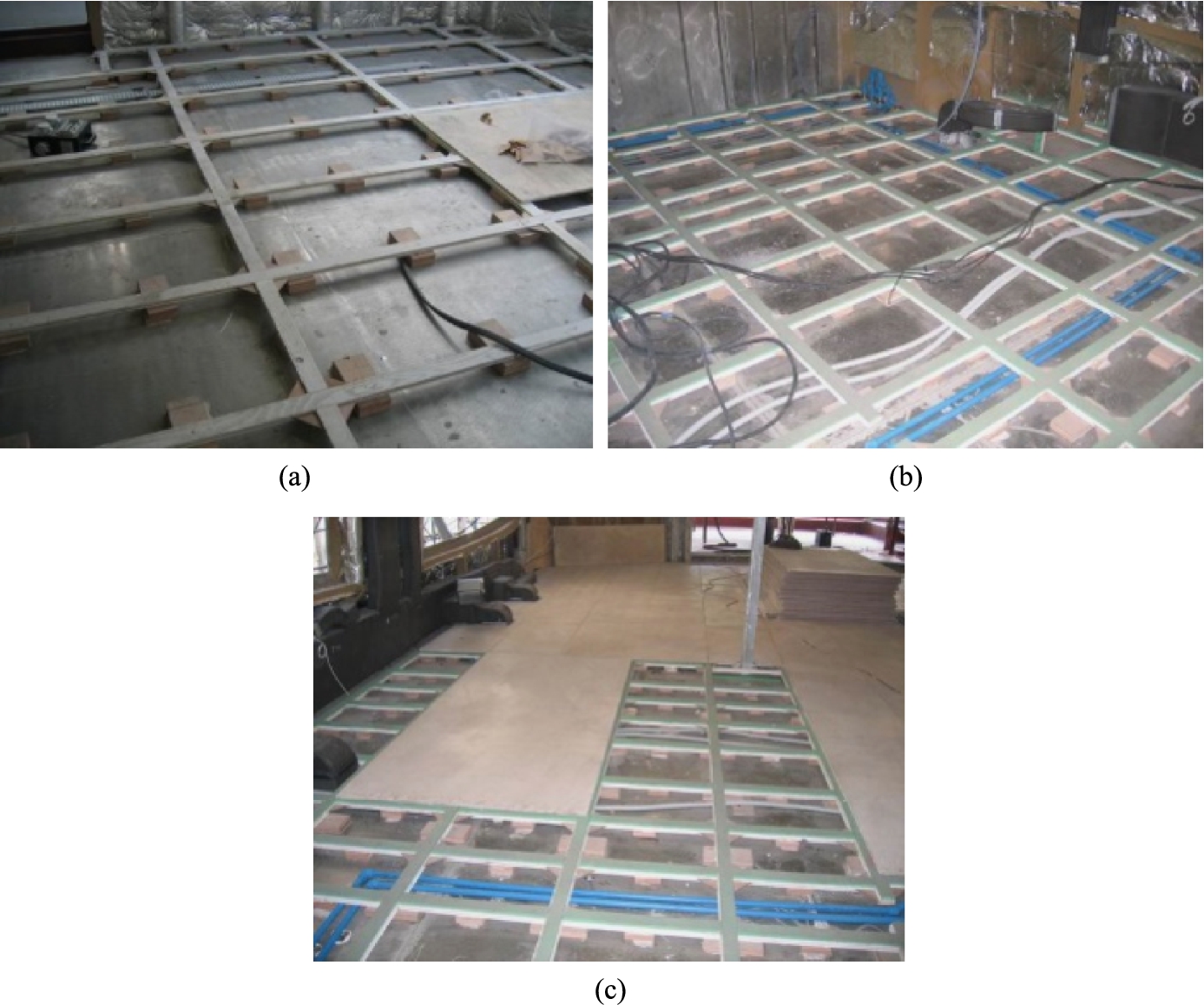
The various phases of a floating floor installation: (a) wooden listel grillage; (b) rubber strips glued on listels; (c) covering with insulating panels.
At first (Fig. 2a) a grillage of wooden listels is laid on the steel (or aluminium) plating with intermediate wooden chocks; then rubber strips are glued on the listels (in green in Fig. 2b); insulating, special panels are laid on the grillage (Fig. 2c) creating the walking surface to be finally covered with different type of coatings. The effect of such a solution is to eliminate most part of uncomfortable vibrations coming from the engine room thus increasing the comfort level of the yacht. A study on absorber materials to be used in the outfitting of megayacht decks is described in [10].
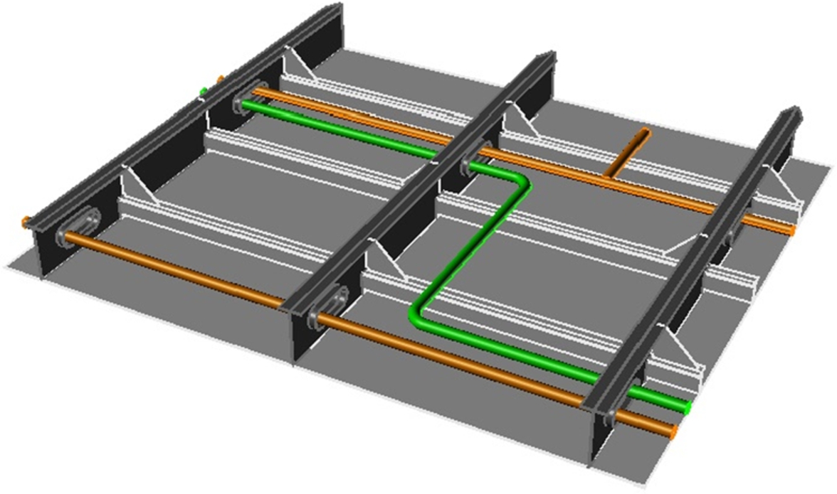
Example of reverse deck structure.
If one looks at this common solution with attention, it clearly comes out that the steel or aluminium plating are not essential to create the walking platform. As a consequence the idea was to reverse the deck layout, putting the plating downward and the beam and stiffeners upward (Fig. 3). This would have allowed to simplify the plant installation and outfitting, as personnel simply has to lay pipes and cables on a stable, downward platform instead of hanging heavy pipes and cables to the ceiling. The floating floor installation was likewise possible with the difference that the holding structure was to be placed on the beam flanges instead of on the plating surface. In addition, the lower surface of the deck plate was ready to house lights and finishing coverings without major complications with respect to the traditional solution.
For this research, the main deck lay out of two megayachts 60 m and 85 m in length has been analysed and compared each other to evaluate which solution seemed to be more advisable to save weight. Both vessels have a length which allows to keep the deck structure very regular in such a way to have the same scantling parameters in all deck areas. Even if the two yachts are from different shipyards, for this research purposes, the scantling has been recalculated according to the Lloyd’s Register [7] regulations. The two yachts have steel hulls and light alloy superstructures with a frame spacing equal to 1300 mm for both hulls, this value often being a standard for this kind of yachts. The two deck structure lay outs are schematically shown in Figs 4a and 4b.
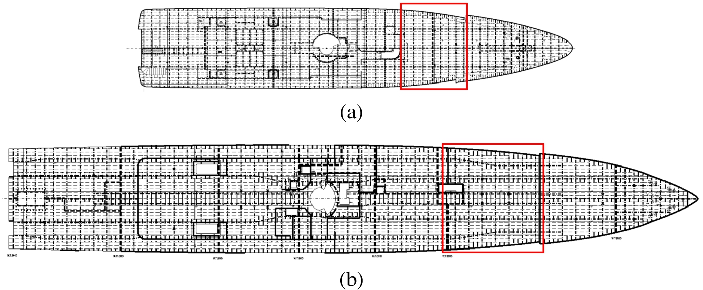
(a) Deck structure lay out of the 60 meters superyacht. (b) Deck structure lay out of the 95 meters superyacht.
In order to simplify the analysis and to reduce the FEM models to the minimum necessary, an area with similar characteristics has been individuated for the two vessels, this corresponding to the fore part of the ship, just beforehand the fore deck elevation, as highlighted in Figs 4a and 4b by the red square. From these two areas a smaller module has been isolated which became the basic module from which all the other have been derived (see Fig. 5).
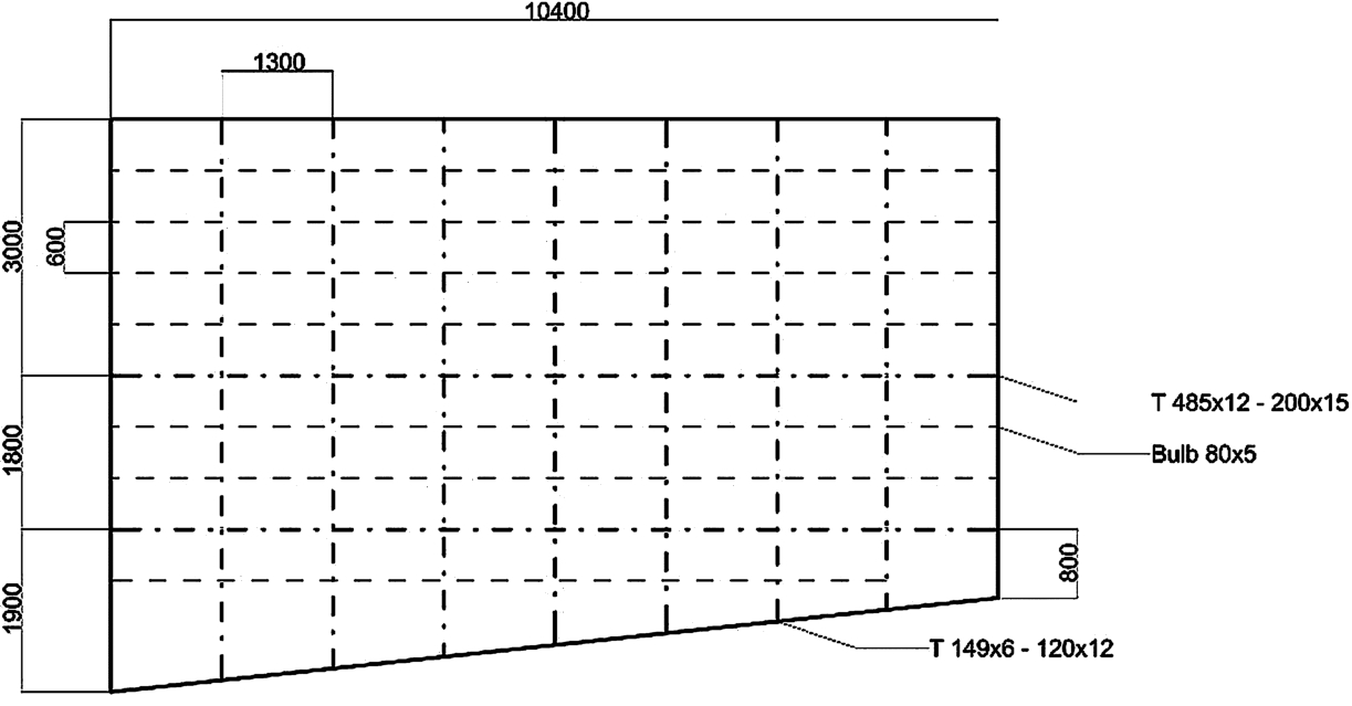
Deck structure basic module.
The first step was the choice of some more layouts that could substitute the original one, in order to compare their different properties. Two series, of three modules each, have been obtained from the basic one:
For this structural Configuration transversal and longitudinal reinforced beams are equal in terms of sectional modulus. The modules have been named 1.1, 1.2, 1.3
In this case transversal girders are significantly smaller and closer to each other than the longitudinal reinforced ones. The modules have been named 2.1, 2.2, 2.3.
The six different structural layouts/models have been selected and created with a constant longitudinal spacing of 600 mm for both Configurations 1 and 2; the frame distance has been varied from 1300 mm (structural model 2.1) to 2600 mm (structural model 1.1). Two intermediate transversal spacing (1730 mm and 2080 mm) have been also studied in order to have a more accurate investigation on the two Configurations. The deck plating thickness has been fixed to 6 mm of Fe520 steel.
Starting from these data the static scantling of each module has been carried out assuming, as load condition, the pressure on the weather deck in a displacement mode, according to the Lloyd’s Register Rules for the Classification of Special Craft, Part 5, Chapter 2, Section 4.5.
The geometry of the six models and the resulting scantling from the performed calculations are resumed in Figs 6 and 7 and in Table 1.

Structural layouts of Configuration 1, models 1.1, 1.2, 1.3.
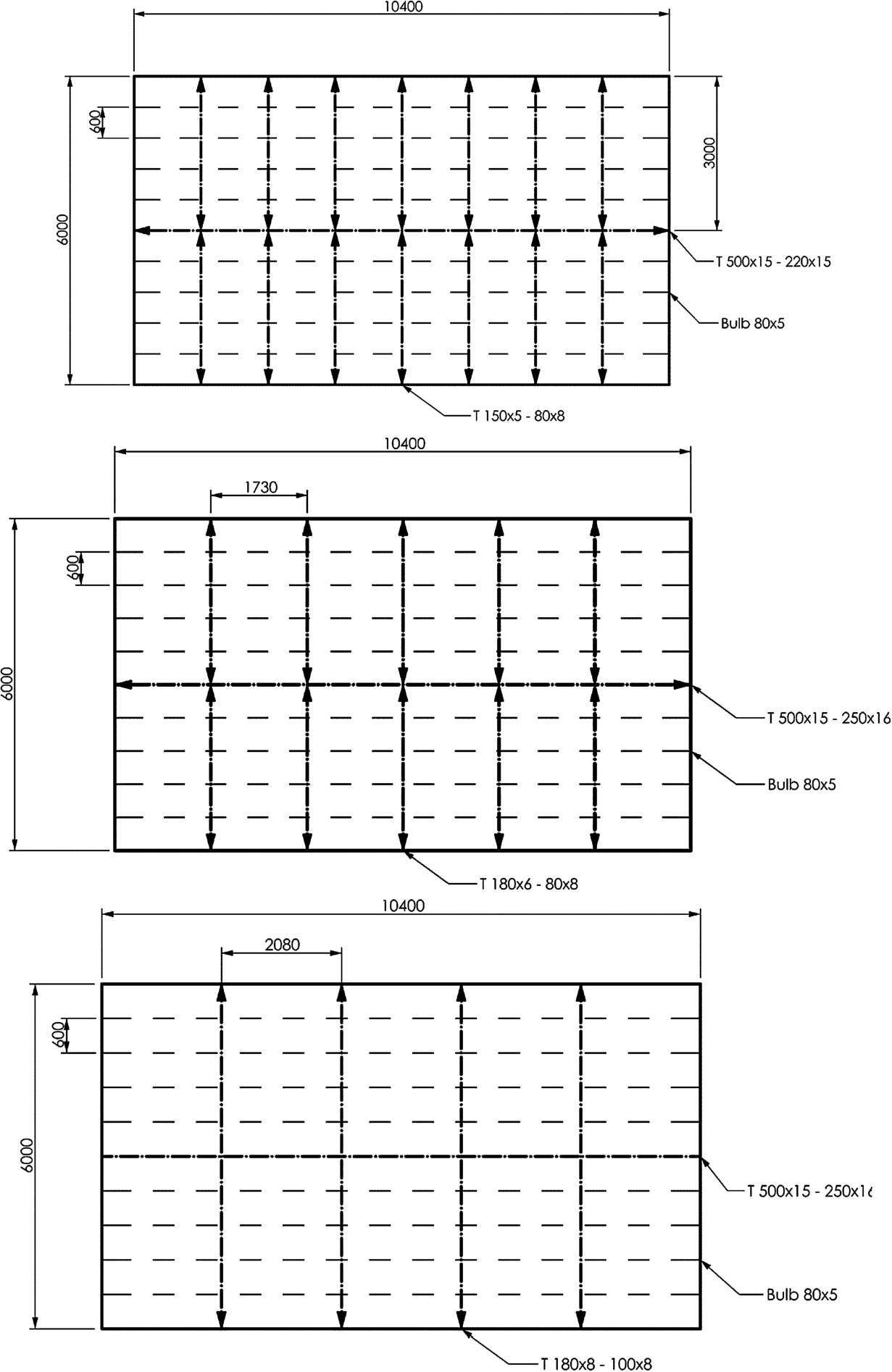
Structural layouts of Configuration 2, models 2.1, 2.2, 2.3.
The proposed models have been tested by using the commercial FE code ANSYS [1] by static structural analysis and eigenvalue analysis for the assessment of natural modes. These analyses are necessary because the structural scantling according to [7] and [2] takes into account neither the holes on the primary beams (necessary for auxiliary plants and weight reduction) nor the interactions among the different structural stiffeners. The FEM analysis is the most reliable way to check these behaviours, apart from specific laboratory tests with higher times and costs.
In each model, reinforced girders and plates have been both modelled as linear 2D shell elements, while linear 1D beam elements have been used for secondary stiffeners. A fine mesh (100 mm) has been used in order to improve the reliability of results especially for the natural mode analysis. In Fig. 8 the meshes of models 1.1 and 2.1 are shown as an example.
Initial dimensional characteristics of the six models
Initial dimensional characteristics of the six models

Mesh density examples: (a) model 1.1; (b) model 2.1.
In order to create a load case as close as possible to a real one, a distributed weight of 50 kg/m2 has been applied to the entire deck portion. The FE model has been constrained by symmetry boundaries on the longer longitudinal edges and by clamps along the shorter sides, which should represent the bulkheads’ rigidity in correspondence of transversal edges. For each module FEM calculations have been run in order to obtain the maximum stress and deformation levels and their location in the numerical model.
At the same time, in order to foresee possible unpleasant vibrations or resonance phenomena, the natural frequencies of panels for each module have been calculated and the scantlings have been adjusted to move the frequencies out of the dangerous range, i.e. around 20% of the propeller frequency (about 25 Hz) and 10% of its double (50 Hz). The dangerous ranges are thus between 20 Hz and 30 Hz and between 45 Hz and 55 Hz.
The results of FEM calculations in terms of maximum stress and deformations and the first natural frequencies are synthetically reported in Table 2. As an example, in Figs 9 and 10 the static stress and deformation distribution, together with the first natural mode deformed pattern are shown for models 1.1 and 2.1.
Because of some inconsistencies of the results reported in Table 2, due to the unnatural mode and deformed shapes, the 6 different deck models have been redesigned in order to verify a structure closer to real cases. In particular, the dimensions of beams and holes have been modified, according to the real scantling procedure and construction requirements imposed by shipyards:
Standard web’s holes of
Web’s hole area not greater than 40% of the total web sectional area, so beams in Configuration 1 not smaller than 450 mm;
Configuration 1 beams’ web not thicker than 12 mm;
Configuration 2 beams’ web not higher than 200 mm (Fig. 12);
Configuration 2 beams’ web not thicker than 10 mm.
The new dimensional characteristics of the six models are reported in the next Table 3.
Results of structural and natural eigenvalue analysis on the six models with outfit weight
Results of structural and natural eigenvalue analysis on the six models with outfit weight

Model 1.1: (a) static stress distribution, (b) static deformation distribution, (c) first natural eigenmode.

Model 2.1: (a) static stress distribution, (b) static deformation distribution, (c) first natural eigenmode.
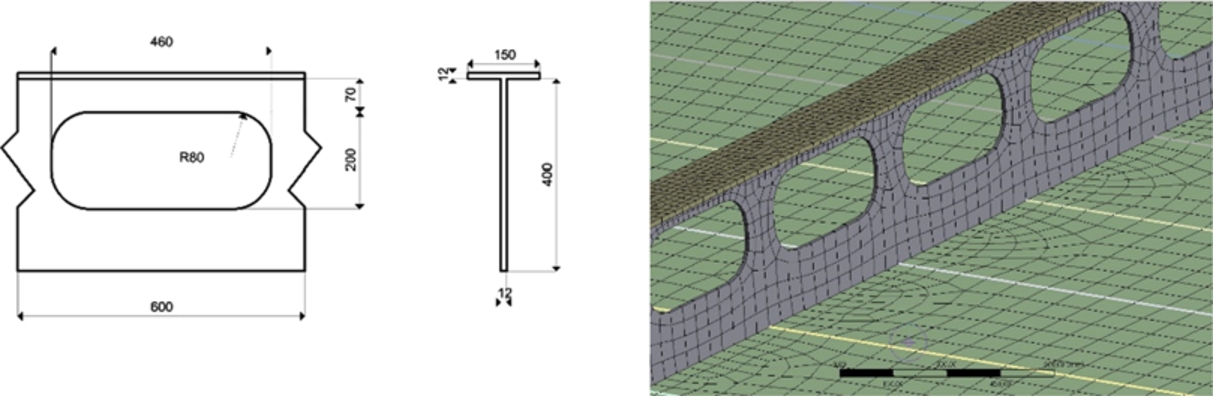
Configuration 1 hole.
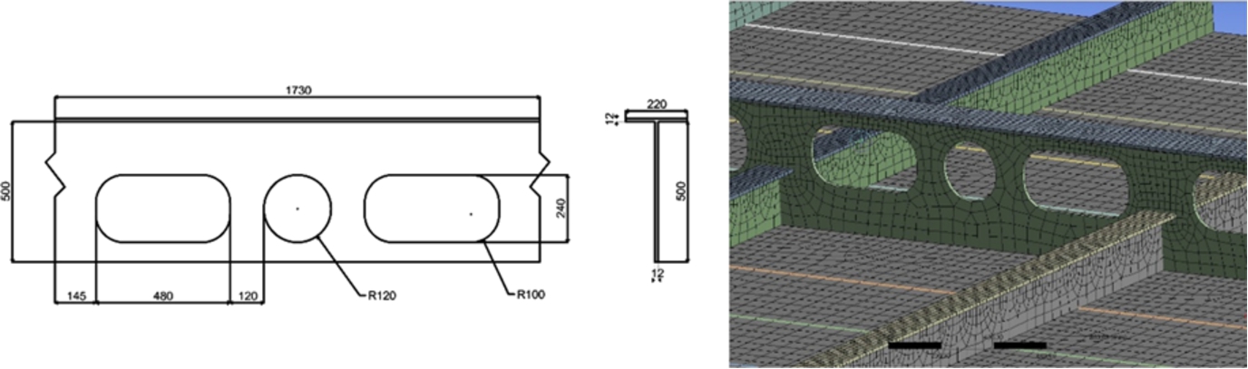
Configuration 2 holes.
Dimensional characteristics after the redesign due to construction requirements
The first modification is due to the standard dimension of pipes used on board: referring to the same standard for each yacht allows the shipyard to simplify the production of beams and girders making it faster and cheaper. The other specifications came from the designers’ experience and they consider the needs of the structure in terms of stress resistance, durability and construction simplicity (in relation with quality, time and cost of production).
The layout of all models have been then remodelled and analysed, both with static and modal FE analyses; while the structural capability to static loads has not been modified by the aforementioned construction requirements (Table 4), the first eigenmodes (Figs 13 and 14) are more realistic then the one reported in Figs 9 and 10.
Results of structural and natural eigenvalue analysis on different structural models after redesign due to construction requirements

Results of stress and modal analyses after the redesign according to construction requirements: Model 1.1: (a) static stress distribution, (b) static deformation distribution, (c) first natural eigenmode.

Results of stress and modal analyses after the redesign according to construction requirements: Model 2.1: (a) static stress distribution, (b) static deformation distribution, (c) first natural eigenmode.
The variation range of the total weight is quite negligible (up to 6%). From the stress point of view, Configuration 1 has to withstand higher loads, but it less deforms then Configuration 2; this aspect is led to the fact that the scantling of structural element between the two Configuration is very different. In fact, following the LR Rules, the direct calculations assume a sort of interruption (fixity) when a secondary stiffener encounters a reinforced beam. The analysis on Configuration 1 shows results closer to this condition, while for Configuration 2 it has to be considered a non-realistic approximation. The main parameter that lead to this different behaviour is the ratio between the dimensions (mainly the height) of stiffeners and beam; in Configuration 1 the reinforced beams are much higher than the stiffeners (the web’s height is more than twice the height of the stiffener) and they provide a perfect support for them. The more similar dimensions of beams and stiffeners in Configuration 2 make them bear part of the beams load, instead of being completely supported by them.
A further test has been carried out on the six numerical models, applying a sinusoidal force to each model in order to evaluate its harmonic response. These analyses gave a confirmation of the previous modal results: if the structure is correctly modelled and supported, then from the frequency response graph it will result an absolute maximum in correspondence of the first mode found in the modal analysis. As this will happen for any kind of frequency response, acceleration, velocity or deformation, in this case acceleration has been taken into account. The peak in the harmonic response, both in terms of velocity and acceleration, could lead to comfort and fatigue problems. A possible solution to reduce the resonance peak could be the adoption of a tuned mass damper [9].
Since all models only represent a portion of a deck, it was impossible to represent the behaviour of the real harmonic forces due to mechanical propulsions as affirmed by Pais et alii in [3]; for this reason, a unitary force of 100 N has been applied to the models.
As stated by Vergassola et alii in [13], structural damping must be taken into account in harmonic and dynamic FE analyses. A standard damping value assumed for steel is 2%, that complies with the results of the investigation.
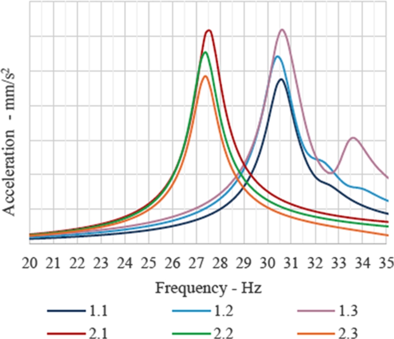
Harmonic response of different models of deck structures.
In Fig. 15, the damped acceleration on the vertical axis for all models is reported.
As expected, the curves have a peak in correspondence of the first natural frequency of the panel. The presence of other smaller peaks is due to higher modes with similar modal shape of the first one; as an example, in model 1.3, the second evident peak around 33.8 Hz corresponds to the eighth mode of the structure, which has a deformation shape similar to the first one.
In each Configuration, it can be seen how the acceleration is inversely proportional to the spacing of transversal structures. This is probably due to the fact that greater spacing allows smoother structural displacements.
The last parameter that has been considered in this investigation is the welding length necessary to build the six considered models. The importance of this parameter is due to the influence of the total welding length on the final construction cost. In particular, the welding of the I order structural elements, both longitudinal or transversal, is generally more influent in the overall construction cost of a deck because it cannot be done with an automatic laser procedure (average speed of 1 m/min) and it should be unavoidably done by manual welding (average speed 0.3 m/min). This makes welding slower and more expensive.
Since each model is a kind of longitudinal layout, the differences in the welding length mainly depend on the number of transversal primary elements, as it can be seen in Table 5.
Analysis of the welding length
Analysis of the welding length
As expected, the largest welding length takes place for Model 2.1, which has the greatest number of transversal elements.
Of course, even if the welding length is greater in Configuration 2, the beam thickness is smaller. This means that the increment of welding time and cost is not necessarily proportional to the length only, but it also depends on the different welding difficulties imposed by the small thickness of plates.
Considering a welding speed of 0.3 m/min, the difference between the required construction time of model 1.1 (335 min) and model 2.1 (438 min) is equal to about 1 hour and 40 minutes.
Since the number of the study cases is limited, a statistical approach would be inappropriate; nonetheless, the typical statistical parameters that can clarify the distribution of the obtained results have been calculated and reported in Table 6.
Analysis of results
Analysis of results
From the analysis of the attained results some general considerations can be drawn.
From Table 6 it is clear that the complete variation of weight from the heavier to the lighter model is not so wide (only 6% of the average) but it can still make a difference considering the whole ship’s structures.
Both the minimum and the maximum weight occur with a spacing of 2080 mm (Table 3). The maximum value, Model 2.3, is the one with the greatest spacing in Configuration 2 and it was likely to be the heaviest. Considering the structure from a merely static point of view, the weight usually decreases with the spacing until it reaches a point where the transversal elements are too many and, however small, they generate an over-reinforced structure that is bound to be heavier than a proportioned one, as it happens passing from Model 1.2 to 1.3. In Configuration 2 this point has not been reached, the weight simply increases with the spacing.
The maximum global stress occurs always on the external part of the beams or girders and, in particular, in the fillet of the connection holes. This location demonstrates the dependence of the value of the maximum stress from the geometry of the hole itself. To a certain extent, greater radius improved the strength of the structure helping to distribute the stress. It would then be advisable to evaluate a proper shape of the holes for each element, and probably even eliminate the most external hole, which is the most stressed one.
The problems deriving from this kind of solution are mainly practical. A different approach for each beam or girder will lead to enormous complications. The standard for web’s holes, which may vary from a shipyard to another, is fundamental to keep the connection design as simple as possible in order to avoid space wasting, that is always a priority in yacht design. Besides standard geometries simplify the production of the webs, reducing the overall cost and time of the construction.
The flange stress depends mainly on the properties of the beam (i.e. moment of inertia, section modulus, shear area) and of the panel globally; the shape of the web’s holes, as far as the web’s properties remain the same, does not influence it. It is confirmed by the fact that flange stress seems to have almost the same trend of the deformation, which is not true with the global stresses.
In both configurations, following the LR rules, the direct calculation used in this work to size the stiffeners considers them as long as the transversal spacing. This assumption implies a sort of interruption or fixity of the stiffener when it encounters the beam. The analyses on Configuration 1 show results close enough to this condition, while for Configuration 2 it is a greater approximation.
What makes the two configurations different from this point of view is the ratio between the dimensions (mainly the heights) of stiffeners and beams: in Configuration 1 the beams are much bigger than the stiffeners (the web’s height is more than twice the height of the stiffener) and they provide a perfect support for them. The more similar dimensions of beams and stiffeners in Configuration 2 make them bear part of the beam load, instead of being completely supported by them.
Another reason of greater deformations in Configuration 2, is that it is heavier so its own weight generates a slightly bigger load. Anyway, the weight increment alone would not be enough to justify the difference in deformation.
The structure characteristics that mostly affect frequency are weight and stiffness: generally, a heavier structure has lower frequency and a stiffer structure has higher frequency. However, it is not simple to predict how much a change of one of these parameters will affect the dynamic behaviour of the whole panel.
For what this study is concerned, the following assumption is verified: Configuration 1, which is lighter (with the same spacing) and less rigid, has greater first natural frequencies in all of its variations.
FEM modal analysis can give reliable results if loads are properly defined and applied. To achieve these condition loads should be applied by a distribution of concentrated masses as pressure cannot be used in this kind of calculations. To find the right sizing, instead, it is necessary to make various tests and evaluate the shape of the deformation of the first mode. As well as the global stiffness of the structure contribute to determine the value of its first natural frequency, the “distribution” of this stiffness contribute to determine the shape of the first mode. For example, in the Outfitting weight calculations chapter I have shown how a numerically suitable solution could be in fact not completely reliable.
Since the characteristics of the propeller (i.e. position, dimension, velocity, number of blades) are chosen before completing the structure design, the safe range of frequencies is part of the requirements the structures have to fulfil. As done in the present work, the structure department of the shipyard starts from these data, along with the general arrangements specification and the selected register’s requirements and performs analytical calculation to evaluate local and global properties of the structures, including first natural frequency.
Longitudinal structural layout is nowadays the most common solution for megayachts for many reasons; first it ensures a greater longitudinal strength and, secondly, a higher resistance to buckling phenomena especially in the deck structure. In addition, the longitudinal lay out has a smaller number of structural components and, consequently, a reduced welding length. Despite these positive aspects, the main disadvantage of a longitudinal structure is the fact that the construction is slightly more complex because of the higher number of joints: in the last years the trend in case of medium size yachts (up to 40 meters in length), for which global loads are not exceedingly demanding, is to return to a transversal layout. For this reason, the competition between transversal and longitudinal lay out is again a topical subject for designers and researchers.
In this research, six different deck structural layouts have been modelled and tested by the Finite Element Method in order to evaluate them from a static and dynamic point of view. Two Configurations has been analysed with three variants each: Configuration 1, with transversal and longitudinal reinforced beams equal in terms of sectional modulus and Configuration 2, with transversal girders significantly smaller and closer to each other than the longitudinal reinforced ones.
The principal pro of Configuration 1 is the reduced weight, together with smaller panel height and shorter welding length. This configuration is also less deformable, even if the variation range is not particularly significant. Configuration 2 is heavier and more deformable and it has higher welding length; on the other hand this configuration reduces the maximum stress values and the first mode shape has lower eigenvectors, which leads to lower level of vibrations.
The choice of the model for the structures of a yacht, of course, is also influenced by the peculiarity of the ship itself that could be often in contrast with what the optimal solution of the structural assessment could be. The starting point of a new structure design, in fact, is usually the internal general arrangements: it defines the vertical space necessary for structures and plants as well as the longitudinal and transversal subdivision. The outfit of present vessels is really very complex and it is by far the most important part of a yacht construction and it has a great influence also on the structural choices. The bulkheads’ disposition is generally a consequence of the internal subdivision of the ship and it may influence the choice of the frame spacing. Another important issue is the final purpose of the vessel: just to give an example, a yacht focused on speed performance should be as light as possible preferring Configuration 1. On the other hand, when a quite small difference in weight does not make any significant difference in terms of performance, a more resistant and comfortable structure such as Configuration 2 might be a more suitable choice.