
Abstract
Permanent magnet synchronous motors (PMSM) are now the focus of application in electric vehicle. Unbalanced magnetic pull (UMP) have been identified as the main cause of noise and vibration in PMSM, rather than torque ripple and cogging torque. In this paper, analytical model of unbalanced magnetic pull from non-uniform magnetic field is investigated theoretically based on Maxwell stress tensor approach. Then, a procedure for calculating magnetic forces based on the 2-D finite element method (FEM) is presented. The FEM results validate the magnet distribution and UMP of analytical results. Also, experimental measurement of electrical quantities and forces with static eccentricity were carried out with one special test fixtures. The analytical model is validated by comparing their results with finite-element and experimental under statistic and dynamic eccentric. Relying on the unique assumption of one-dimensionality, the present analytical model appears as a useful tool for parameters design and behavior understanding.
Keywords
Introduction
Use of high power-density permanent magnet synchronous motors (PMSM) in hybrid electric vehicle (HEV) presents a promising potential. This is, due to the high torque density, high efficiency, small size, fast response and reliable operation of these motors [1, 2, 3]. It has a profound effect on the performance and the capacity of a PMSM for electric vehicle through its configuration, operating speed, and resonances. Therefore, a great number of efforts have been made to achieve technological innovations and market competitiveness. Among them, size reduction, speed increase, and cost reduction have been the main concerns. However, as the increase of speed and power of PMSM, much more smooth and quiet operation is required. Therefore, noise and vibration of PMSM are considered a critical issue [4].
In general, due to the mechanical connection between the PMSM’s rotor and gear mechanism, the installation deviation, mass eccentricity and bearing faults can inevitably lead to rotor eccentricity. Mechanical vibrations because of rotor eccentricity can lead to various types of operating malfunctions such as bearing failures that can precede rotor-stator rub. Also, asymmetric air gap can result in non-uniformly magnetic fields, where a transversal excitation termed Unbalanced Magnetic Pull (UMP) is generated [5, 6, 7]. It is known that the unbalanced magnetic pull (UMP) has the adverse effect to increase the rotor-stator eccentricity, viz., rotor-stator eccentricity and UMP mutually affect each other [8], i.e. the mechanical and magnetic coupling effect. Nonlinear vibration induced by UMP become more and more serious [1, 4]. Consequently, it is essential to establish UMP model considering mechanical and magnetic coupling effects, which are of great theoretical significance in electro-mechanical coupling analysis and fault diagnosis of PMSM for HEV.
Determination of precise UMP has been an intensive research topic for many years. UMP can be computed precisely by using the finite element analysis [8, 9, 10], but this approach is not only computationally expensive but also unable to provide an insight into the origin and key factors in the production of UMP. Some simple analytical analysis and its effects on the rotor of electric machines are put forward. Pennacchi [11] and Frosini [12] have developed a method to calculate the effects of the UMP, which is suitable to simulate the dynamical response of complete generators (and also of complete sets of turbine and generator). The harmonic spectrum of the UMP is evaluated and the presence of non-linear effects highlighted by Dorrell [13] and Smith [14]. It also illustrated that additional vibrations at twice-supply frequency may be generated by certain connections. The general solution for UMP when there is static eccentricity results in a steady pull plus a twice supply frequency vibration in an induction motor was confirmed. Vibration characteristics of hydro-generator rotor due to UMP also been studied by some researchers. Guo et al. [15] expressed a nonlinear UMP of different numbers of pole pairs under no-load state in analytical, and influences of unbalance forces on Jeffcott rotor dynamics were researched. Gustavsson and Aidanpaa [16, 17] and Yang and Kim [18] calculated UMP by considering the eccentricity and the axis change of hydro-generator rotor, and analyzed the rotor stability and imbalance response.
The research mentioned above is mainly focused on the large-scale hydro-generator. When it comes to a permanent magnet machine, even without excitation, there will be UMP due to the magnets; essentially, in this machine, the UMP will increase with loading and there will be additional vibrations. Although several papers [19, 20, 21], for instance, have studied the UMP in electrical machines from the electrical point of view, an analytical technique for predicting the instantaneous magnetic field distribution in the air gap region of permanent magnet motors with rotor eccentricity is developed. Fewer papers in the literature [21, 22, 23, 24], for example, have attempted to model the UMP for mechanical dynamic analysis. Model of UMP is mainly based on finite element method, but there are actually few studies that address the issue of UMP measurement directly.
In this investigation, Maxwell stress tensor approach was used to analytically model the UMP of PMSM. Based on the characteristic of non-sinusoidal distribution of PMSM air gap magnetic field, the Magnetic Motive Force (MMF) of air gap magnetic field is obtained with theories of armature winding, the air gap permeance of eccentricity rotor is calculated with Fourier series expansion method. With consideration of armature reaction and saturation effect, the analytical model of UMP of PMSM used in HEVs is obtained. Moreover, the present model is suitable for implementation in complex performance models that require an accurate estimation of the effective dynamics properties with less computational cost.
The analytical model was comprehensive validation by FEM and experiment. Firstly, unbalanced magnetic forces of a PMSM used for electric vehicle due to static, dynamic eccentricity are analyzed by finite element analysis. Then, the air-gap electromagnetic field and stress distribution is evaluated for providing an insight into the origin and key factors in the production of UMP. The comparison study between analytical calculate and FEM results is also presented. Finally, one special test fixture was used to validate analytical model. Experimental measurements of forces with static eccentricity are carried out and compared with simulation results.
Analytical modelling
Electromagnetic vibration of eccentric rotor is induced by the radial electromagnetic force, i.e. unbalanced magnetic pull, while the air gap magnetic field is decided by the Magnetic Motive Force (MMF) and the air gap permeance. Therefore, it is essential to analyze the MMFs and the permeance under uneven air-gap. The analytical modelling in this paper is based on several assumptions: (a) iron material permeable is infinite and neglect end effects; (b) the input current is assumed to be three-phase sinusoidal supply; (c) the motor is assumed to have three-phase symmetrical stator windings; (d) surface of the rotor and stator is smooth in the axial direction.
The Magnetic Motive Force
Figure 1 represents the relative position between permanent magnets and the stator armature. The symbol
The relative position between permanent magnets and the stator armature.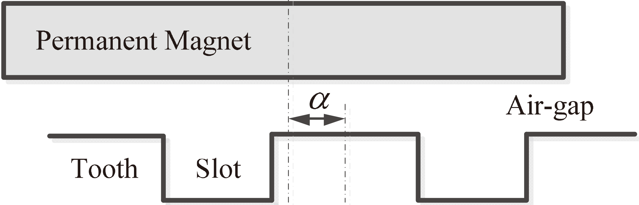
According to the magnetic circuit principle of permanent magnet motor [1], the permanent magnet can be regarded as a constant source of MMFs. The fundamental MMF of surface permanent magnet motors can be expressed as:
Where
The stator winding MMF analysis of permanent magnet motor is similar with induction motors. The permanent magnet synchronous motor for HEV is supplied by PWM voltage sources, but the armature current is approximate three-phase symmetrical sinusoid waveform. According to winding theory of electric machine, the fundamental MMF of A-phase winding can be expressed as [10]:
Where
Where
Hence the MMF of three-phase stator winding is obtained by Eqs (2) and (3):
Where
The cross-section of eccentric rotor.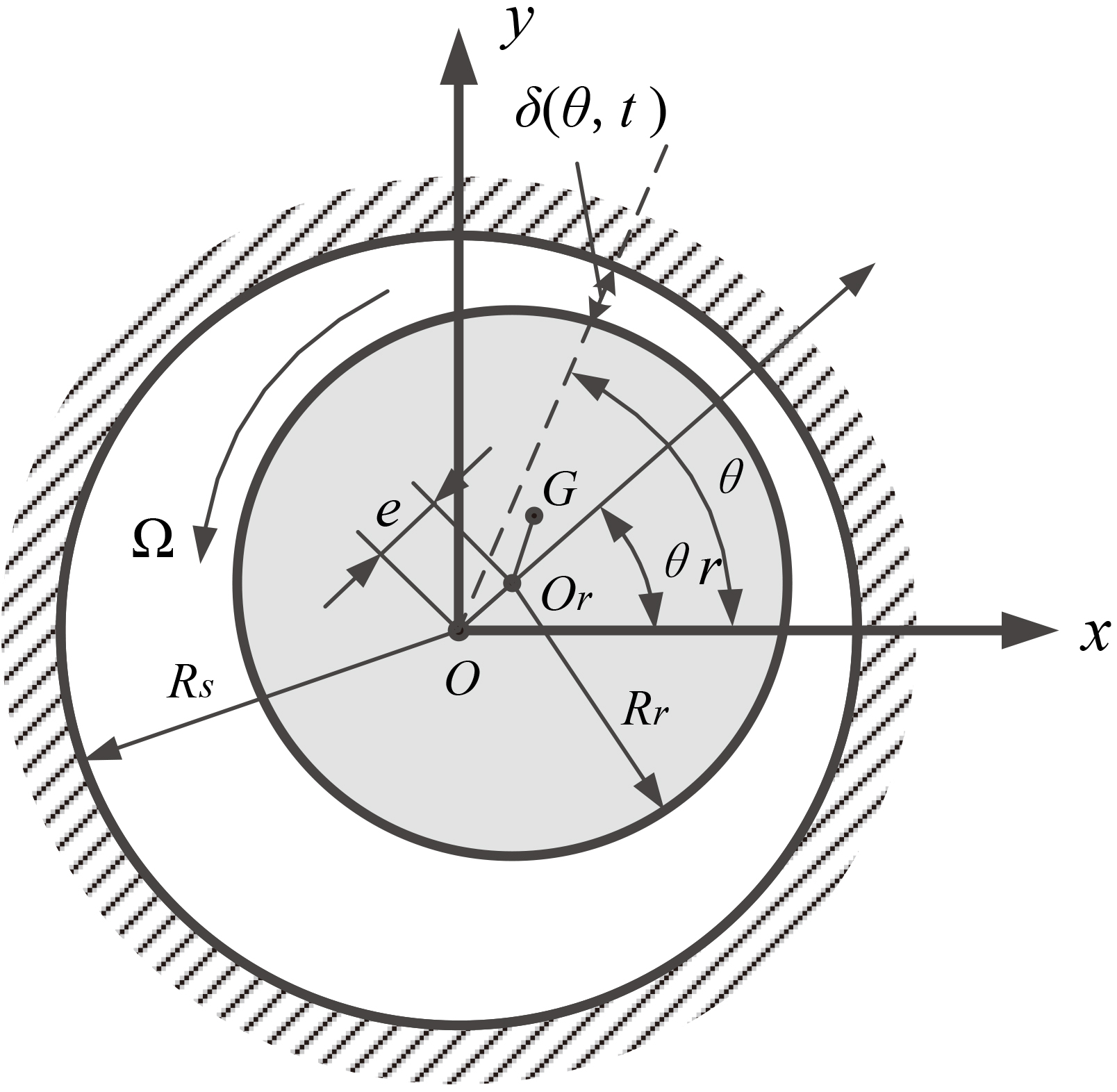
For the case of a PMSM under symmetric load, the resultant fundamental MMF of the air-gap can be expressed as
In which
Figure 2 shows the cross-section of a rotor rotating at a constant angular speed
It is assumed the eccentricity is identical along the longitudinal direction of eccentric rotor, the air-gap length can be approximately expressed as
In which
The air-gap permeance can be deal with a Fourier series:
Where
The Fourier coefficients
The normalized magnitude of the permeance can be represented by
Normalized air-gap permeance coefficient against eccentricity.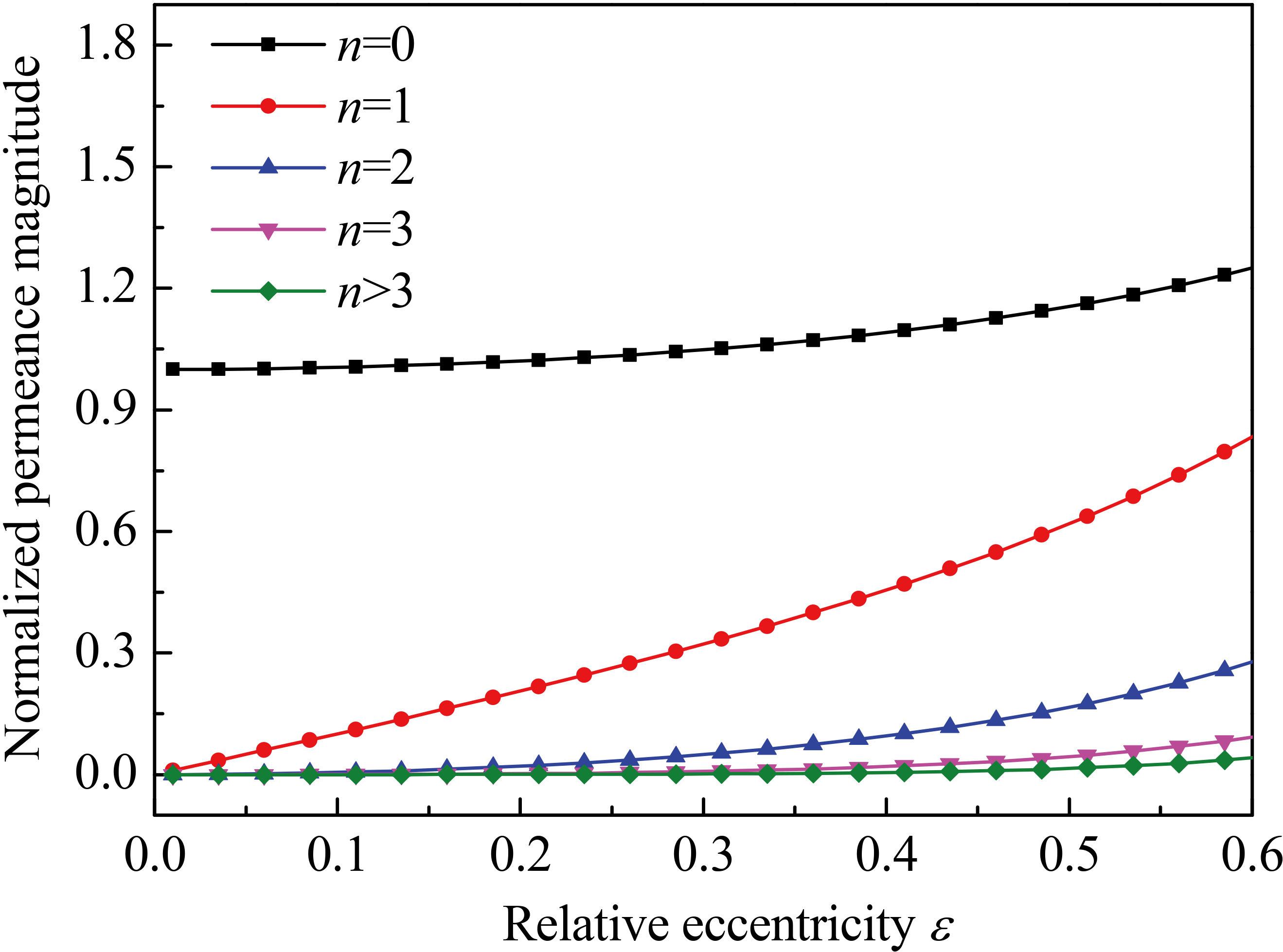
From Fig. 3, it can be seen that as the order
After analyzing the MMF and air-gap permeance, the air-gap density can be obtained:
Substituting Eqs (7) and (8) into Eq. (9), and keeping the first three terms of the infinite series yield:
From Eq. (10), it can be seen that the modulation of the harmonic MMF waves by air-gap permeance produces air-gap harmonic fields with different pole-pair numbers, and the pole-pair number of PMSM for HEV is usually bigger than 2.
According to Maxwell Stress Tensor method, the density of radial electromagnetic force acting on the rotor can be expressed as:
Where
The resulting force can be obtained by integrating the horizontal and vertical components of the Maxwell stress over rotor surface as
The analytical expression of radial electromagnetic force is obtained:
Since [
Substituting Eq. (14) into Eq. (13) and neglecting terms with power number being greater than three, then simple analytical model of UMP can be expressed by Eq. (15):
Where
As can be seen from Eq. (15) the orient of radial electromagnetic force point to the narrow air gap. In the following section, electromagnetic stiffness property of UMP will be analyzed.
In order to validate this model, the radial electromagnetic forces of PMSM for HEV due to static and dynamic eccentricity are analyzed by 2D FEA, and the comparison study between FEM and analytical results are presented.
Main parameters of PMSM
Main parameters of PMSM
Snapshot at start of simulations of consequent pole machine showing higher flux density on right; the rotor is rotated by 60
Air gap flux density distribution on air gap contour.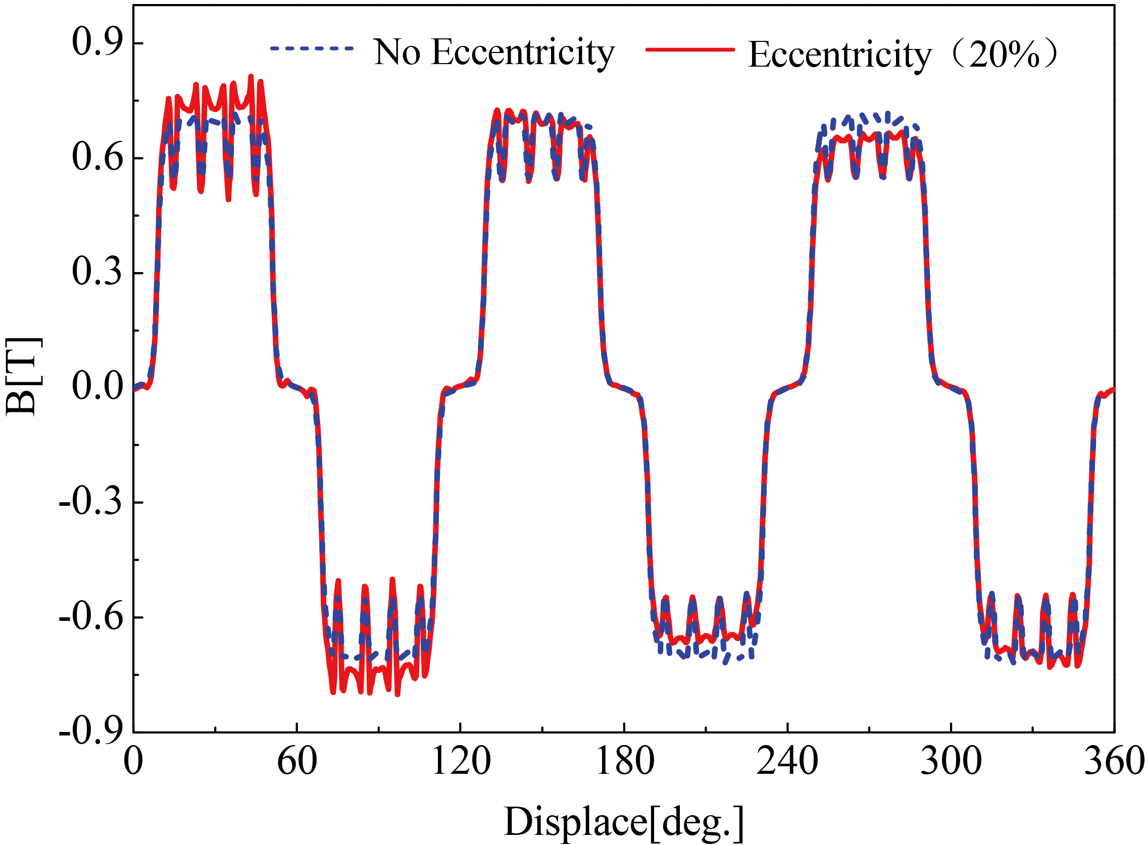
Table 1 presents main specifications of analysis model. The rated output power of model is 80 kW. The application of this machine is electric vehicle drive system. The stator inner diameter is shifted 0.5 mm to consider static eccentricity. The rotor out diameter is also moved to make dynamic eccentricity. The mixed eccentricity means the condition when stator and rotor eccentricity occur simultaneously.
The modeling concepts of static and dynamic eccentricity are presented in [25]. The center of stator core is shift 0.5 mm on the x-axis to make static eccentricity. When the rotor rotates, the position of narrow air gap is same. The center of rotor is moved to consider the dynamic eccentricity. Because the rotating center is fixed, the position of narrow gap is rotating with the rotor movement.
With dynamic eccentricity, the point of minimum air gap (direction of eccentricity) is synchronized with the rotor. In all the simulations, the rotor was aligned at an angle of 0
Radial force distribution.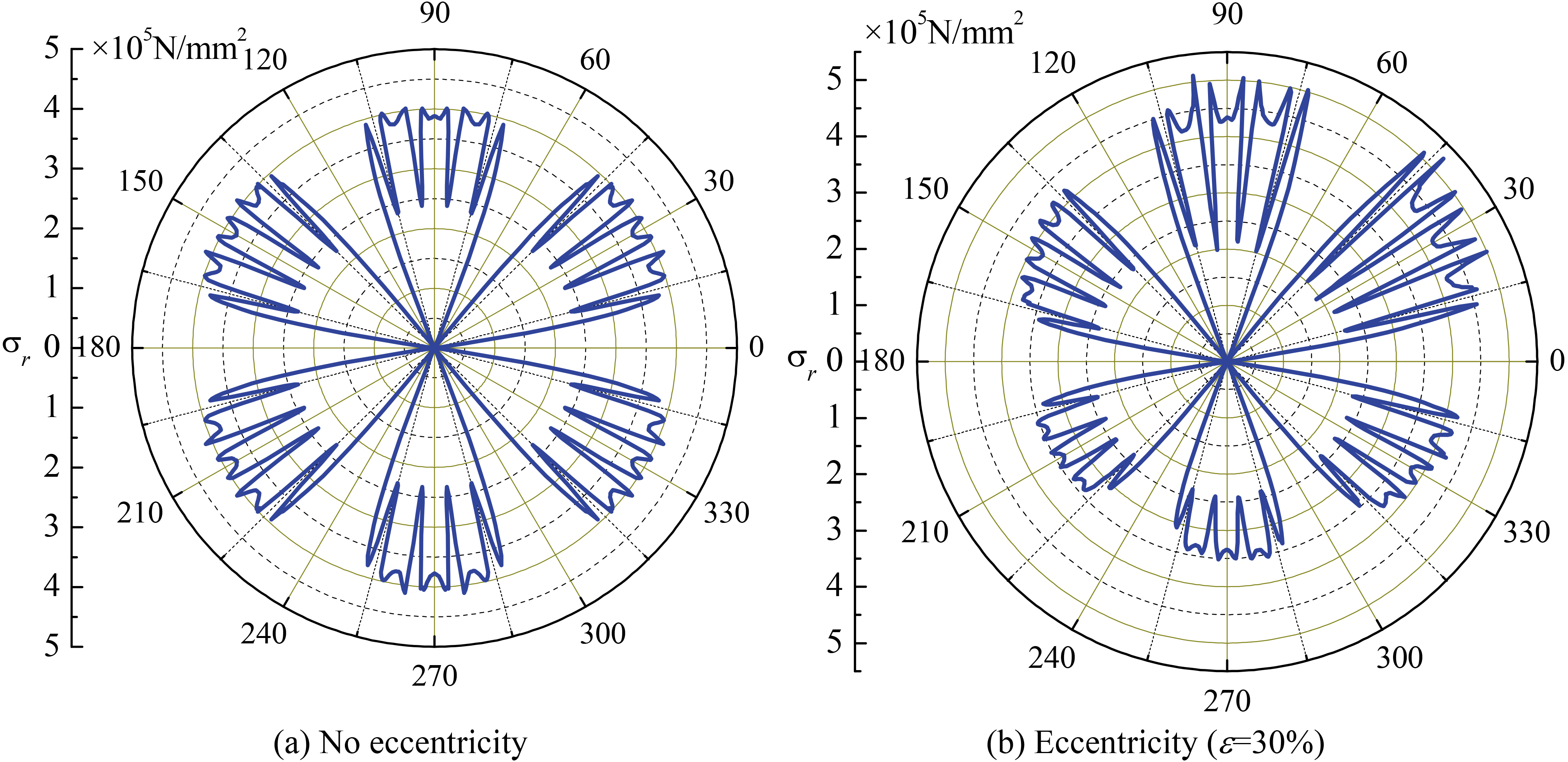
This section will provide an insight into the origin of UMP. Based on flux density from FEM, radial magnetic stress can be calculated by Eq. (11). Figure 6 shows the space radial force distribution in air-gap at specific time. It is obvious that radial force distribution is similar to fully symmetric petal, whereas the radial force distribution on rotor is changed due to asymmetric magnetic field distribution. Radial magnetic stress of the small air-gap position is higher than the big air-gap position, which makes the unbalanced magnetic force.
Unbalanced magnetic pull amplitude with different eccentric condition
Unbalanced magnetic pull amplitude with different eccentric condition
Unbalanced magnetic force with static eccentricity.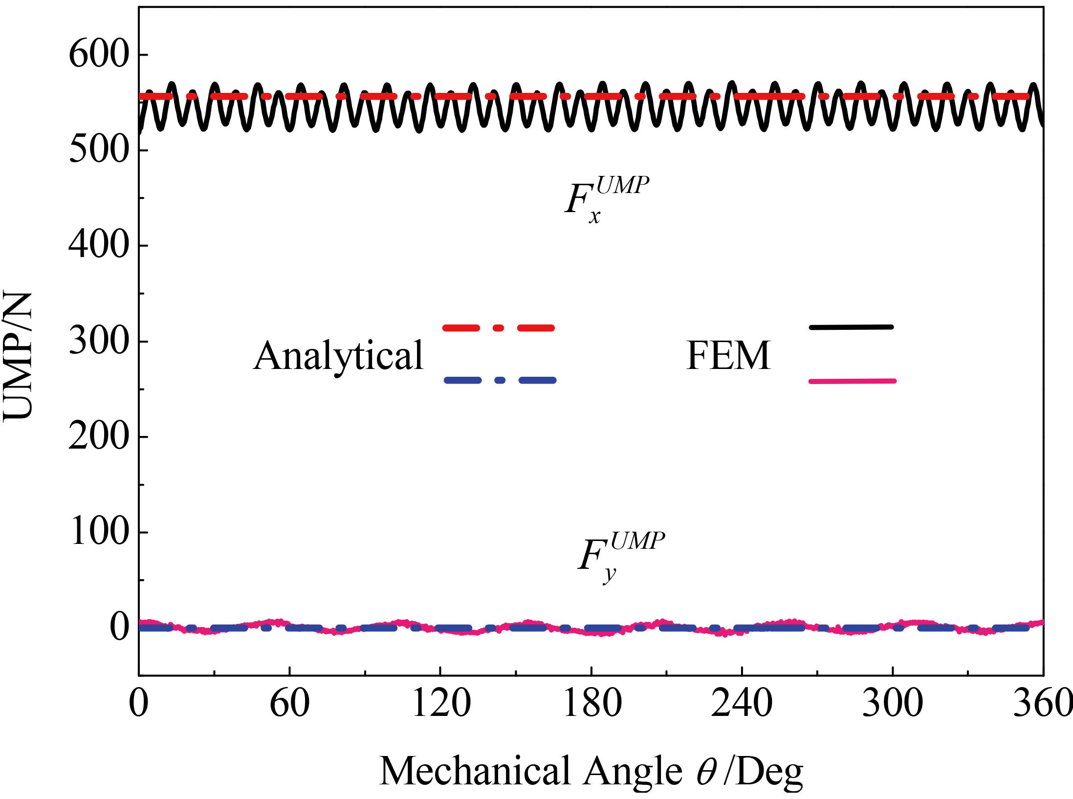
Unbalanced magnetic force with dynamic eccentricity.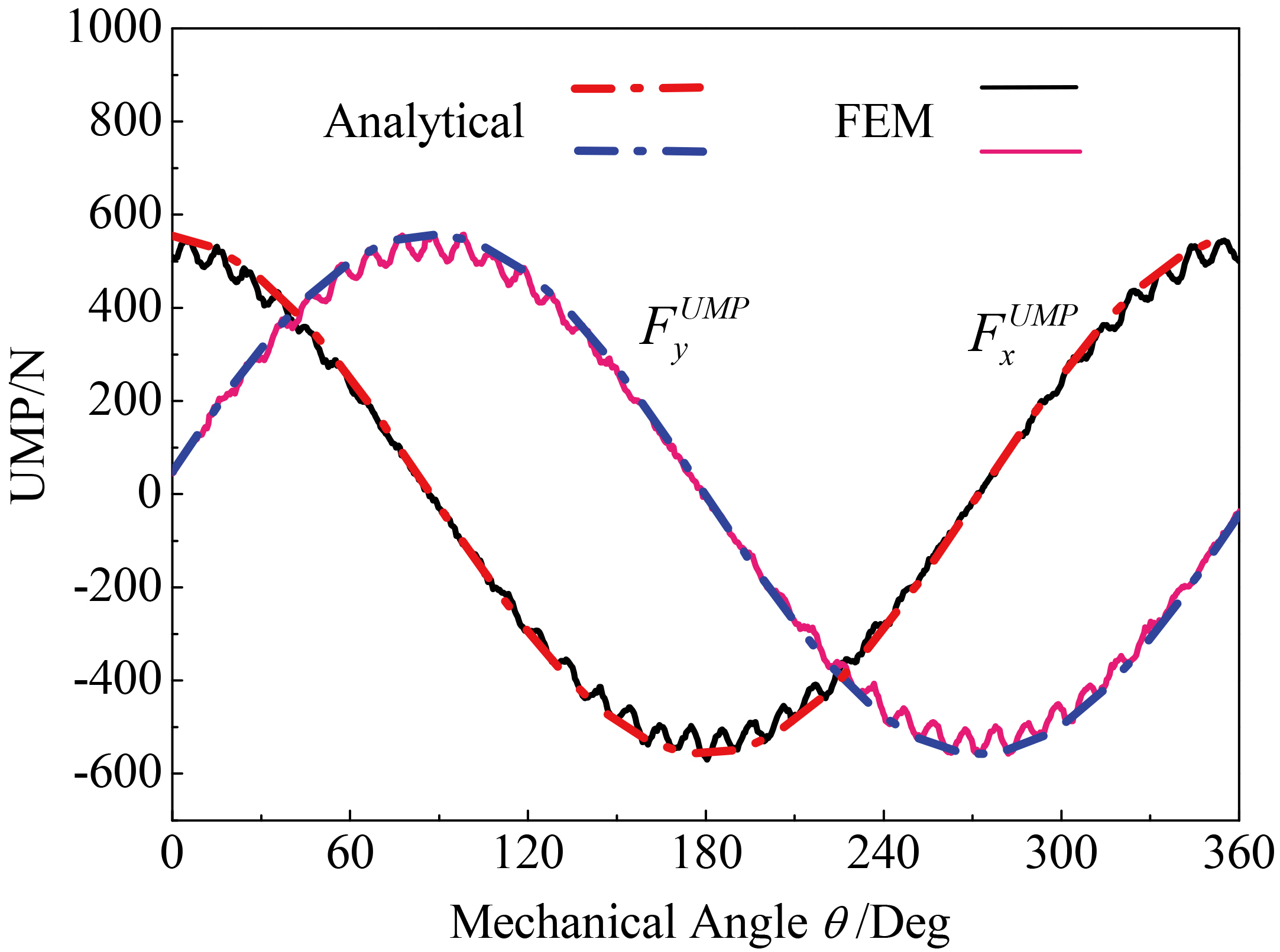
The radial magnetic force on the air-gap contour is calculated by 2D FEA and analytical expression shown in Eq. (14). Figures 7 and 8 show a comparison of unbalanced magnetic force obtained by using FEA and the analytical model at rated load with static eccentricity and dynamic eccentricity. Mechanical angle stands for the rotor rotating angle,
Figure 7 shows the unbalanced magnetic force characteristics with static eccentricity. Because the narrow air gap is located at x-axis component, i.e.
Finally, analytical and FEM calculation with different eccentricity when operate in rated condition were compared, the results are shown in Table 2. As can be seen that error between analytical and FEM is no more than 10%. Consequently, the accuracy of analytical model is basically acceptable.
Experimental fixture to measure UMP.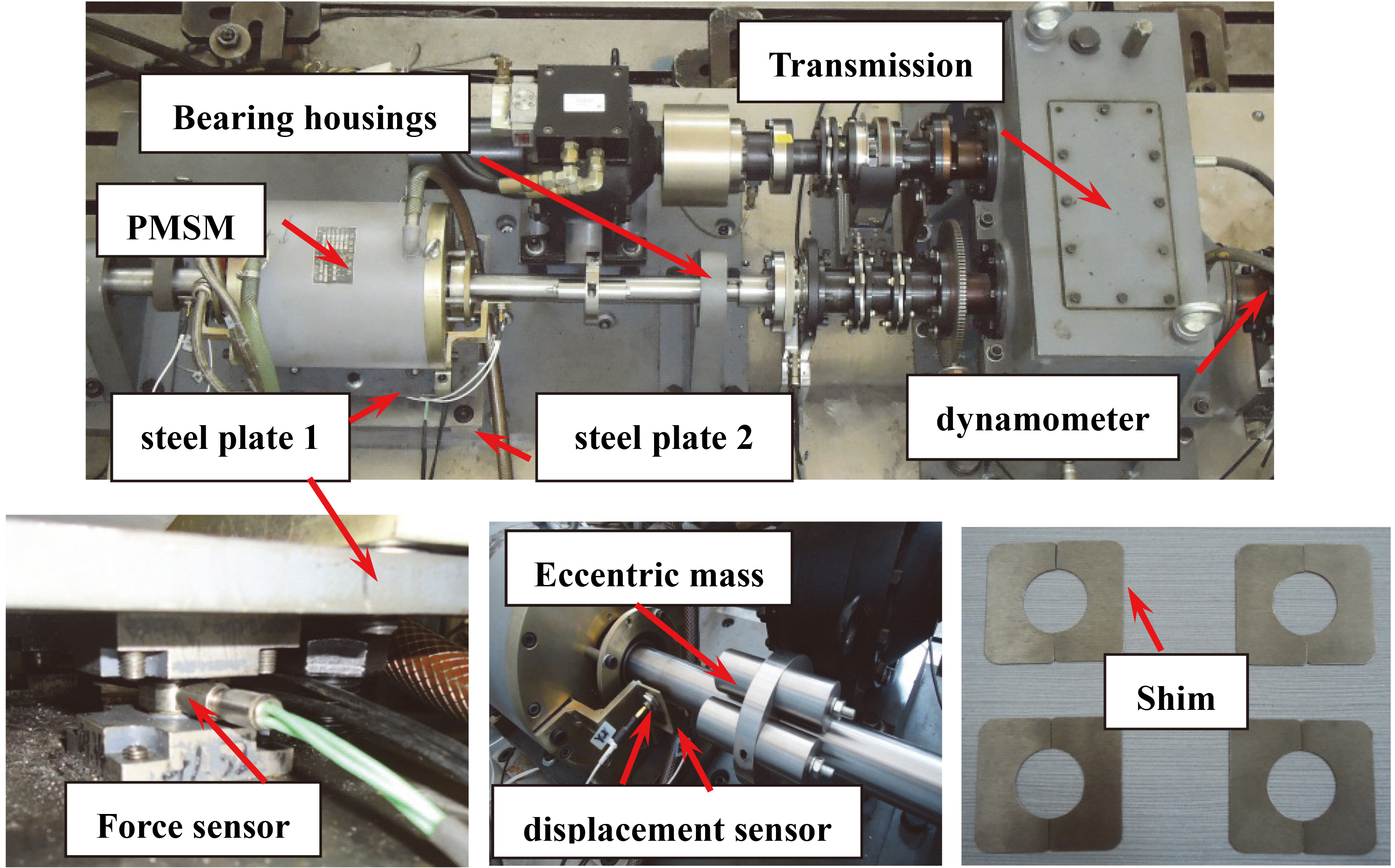
Test fixture
To validate the analytical model an experimental fixture was designed. The fixture (Fig. 9) enables the measurement of UMP with a controlled static eccentricity. This shows the small machine on a force measurement plate. It can measure radial forces in two directions. The multicomponent force plate consists of four force measuring elements. Each element contains a preloaded force sensor for avoid plate vibration. The force sensor contains quartz rings which are mounted between two steel plates in the housing of the sensor. Quartz ring sensitive to pressure measures the force acting in vertical direction on the force plate. The four sensors are mounted between two steel plates (steel plate 1 and steel plate 2) as shown in Fig. 9. The force plate can be fixed with two bolts on the flat for produce preload.
The force measurement is between the stator and rotor so the end-bells of the machine are removed and new bearing housings formed and fixed to the ground plate. That is saying the rotor’s position is fixed. We use shim on the bottom of steel plate 2 to block up force plate to create a static eccentricity. Also, eccentric mass is used for produce dynamic eccentricity when PMSM operate. Therefore the plate is able to measure UMP between the stator and rotor.
Experimental conditions
A concentrated winding PMSM (80 kW) used for electric vehicle were performed with the rotor displaced in the vertical direction to create a static eccentricity. When PMSM was loaded by dynamometer, the current in each phase branch was measured by current sensor. The rotor displacement was also measured by displacement sensor with in vertical direction with the static eccentricity at 300 r/min.
Experimental measurement of rotor displacement.
Experimental measurement of phase current.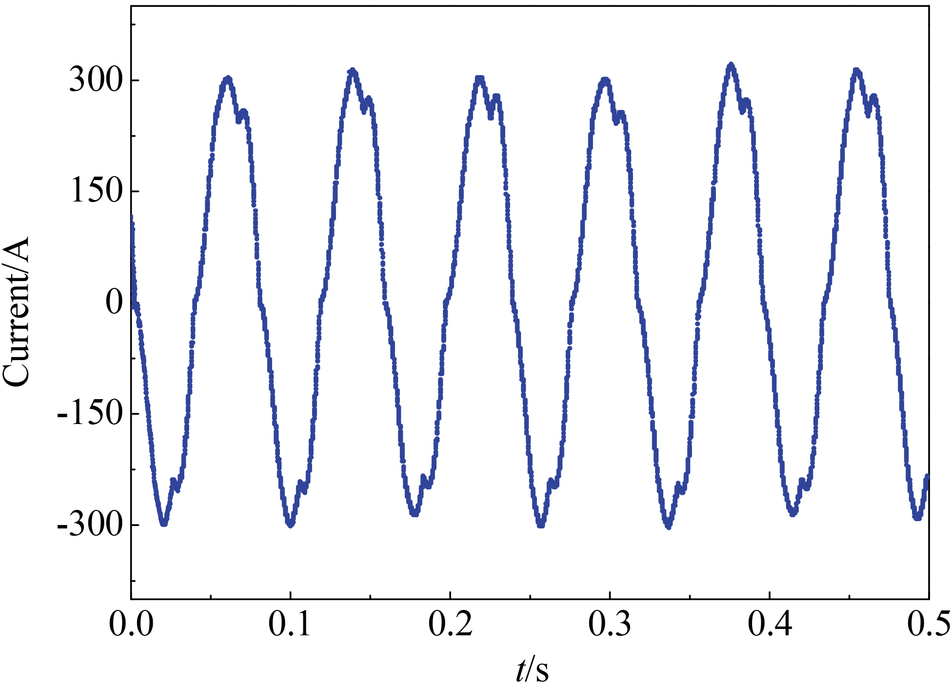
Experimental measurement result of four force sensors.
Simulated and experimentally measured UMP with a static eccentricity of 30%.
Figure 10 shows experimental the measurement vertical displacement, we can see rotor static eccentric is about 0.35 mm and dynamic eccentric is about 0.05 mm after adding shims. Due to the effective air gap of PMSM is 1.5 mm, so the static eccentricity of static eccentricity and dynamic eccentricity are respectively 23.3% and 3.3%. Stator armature current represents the operating conditions of the motor. Figure 11 shows experimental the measurement current, which is approximately sinusoidal wave. The amplitude of phase current is about 310 A.
Figure 12 shows the measurement force waveform of four force sensors in the vertical direction. There are two force sensors measurement value is negative and two force sensors measurement value is positive. The actual experimental UMP is obtained by sum the four force value.
In last section, we got experimental condition: static eccentricity, dynamic eccentricity and phase current, which are substituted into the unbalanced magnetic pull analytical model. The analytical calculated unbalanced magnetic pull due to static eccentricity is about 421 N, and unbalanced magnetic pull caused by dynamic eccentric amplitude is 52.7 N. The results of the experiment are compared with simulation results under the same conditions shown in Fig. 13. We can see that the experimental curve and waveform simulation curve trends coincide. The reason for difference is the effect of the magnetic field harmonics is not considered in analytical modeling. The experimental and simulation results of UMP agree very closely and support the validity of the simulation results.
Conclusion and future work
The main conclusions of this study are:
Based on the idea of modulating the fundamental MMF wave by air-gap permeance and Maxwell tensor method, an UMP analytical model of PMSM generated by the non-uniform magnetic field were proposed. The FEM results validate the magnet distribution and UMP of analytical result. There is no more than 10% error between FEM and analytical results. Also, flux density and radial magnetic stress provide an insight into the origin and key factors in the production of UMP. A special experimental fixture was designed to validate the analytical model. Detailed experimental results agree very closely with analytical calculation and support the validity of the analytical model.
The models are comprehensive validated by comparing their results with finite-element and experimental data. This analytical model can rapidly and correctly predict the multiphysics electromechanical coupling responses of the rotor of PMSM and accordingly provide an opportunity for optimizing the electromechanical design.
Footnotes
Acknowledgments
This work was supported by the Science and Technology Project Affiliated to the Education Department of Chongqing Municipality (Grant Nos: KJ1705135 and KJ1600538) and the Basic Natural Science and Frontier Technology Research Program of the Chongqing Municipal Science and Technology Commission (Grant No: cstc2017jcyjA0221).