
Abstract
A novel sandwiched maglev positioning stage is proposed in this paper. Mathematical model and finite element models are made up to analyze levitation force and driving force on maglev stage in two different structures—ordinary and sandwiched, which can verify the better performance of sandwiched structure. Also, the analysis of the relation between current input and working forces help a lot to the control of the maglev stage.
Introduction
Traditional guide rail contact positioning platform has developed very mature, but problems like friction and abrasion still exist. However, precision manufacturing area, such as microelectronics processing, has an increasing demand on the equipment performance and processing environment. So the magnetic levitation positioning stage rises in response. Magnetic levitation technique is an advanced technology with advantage of zero friction, no wear, no need of lubrication, long life, low power consumption, noiselessness and so on.
There are different kinds of maglev stages, such as with or without rail support. To realize multidegree freedom motion, a maglev stage with rail support [1, 2] will own a redundant structure, which will cause low system response. Maglev stages without rail support [3, 4, 5, 6, 7, 8, 9] make use of the electromagnetic force to achieve levitation. As it is called, levitation performance is of vital importance. And to ensure the precision positioning, positioning control is also very important. This paper introduces one maglev stage with a special structure – sandwiched maglev stage, that has better levitation performance.
The sandwiched maglev stage is made up of one moving platform, four Halbach permanent magnet arrays, four stator windings, as shown in Fig. 1. The four stators lay upper and lower of the moving stage, with the Halbach permanent magnet arrays embedded upper and lower of the moving platform, forming the sandwiched structure. Compared to the ordinary structure, the key feature is that the four Halbach permanent magnet arrays are installed on different surfaces of the moving platform. Also, the four stator windings lay in different planes in correspondence with the magnet arrays.
Schematic diagram of the sandwiched maglev stage.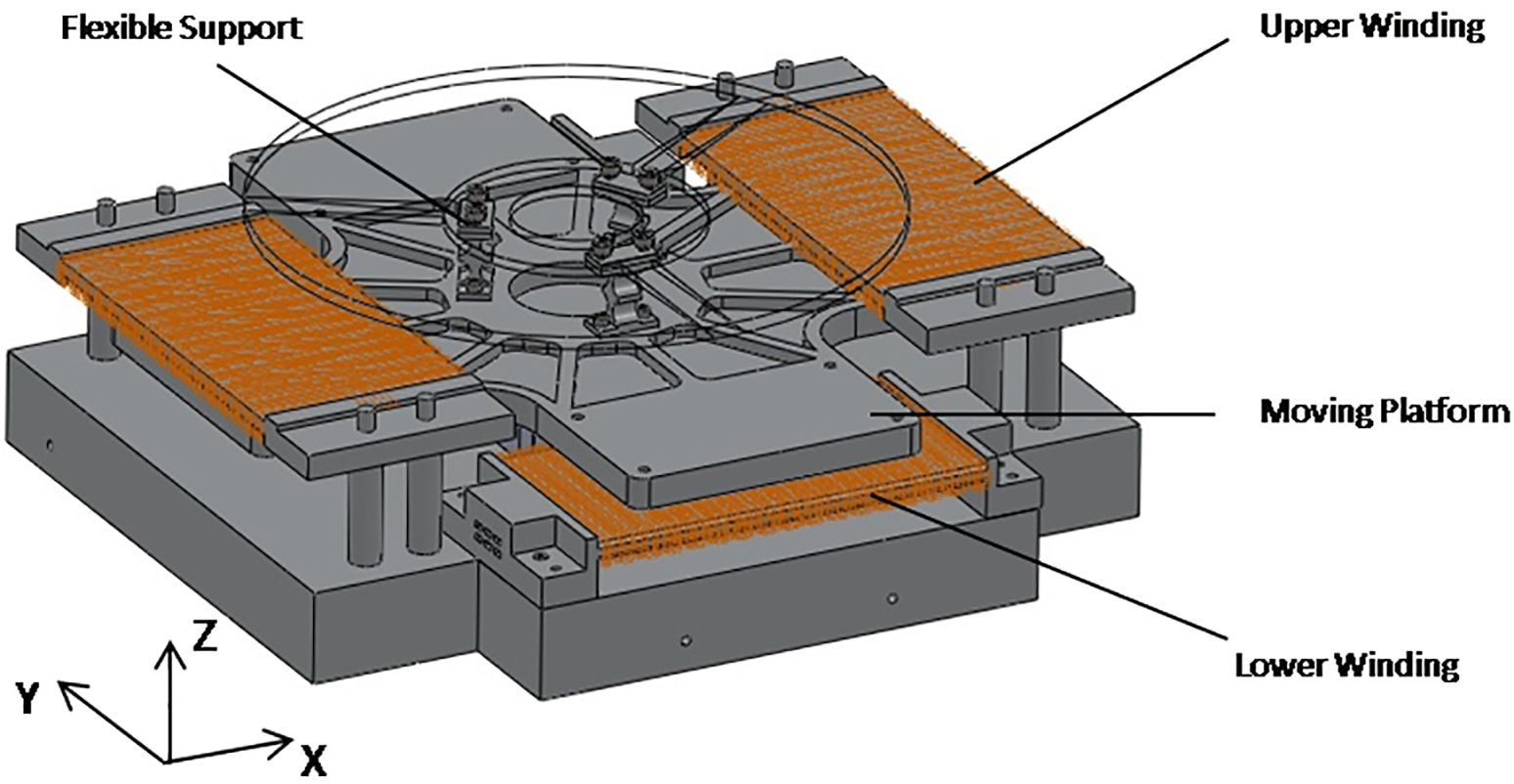
So far, the sandwiched maglev stage has been set up, shown in Fig. 2. The main body of the maglev stage is made of aluminium alloy. The sandwiched maglev stage is an electromagnetic system with double driving. Though the stator windings are mounted on different planes, forces on
Photo of the sandwiched maglev stage.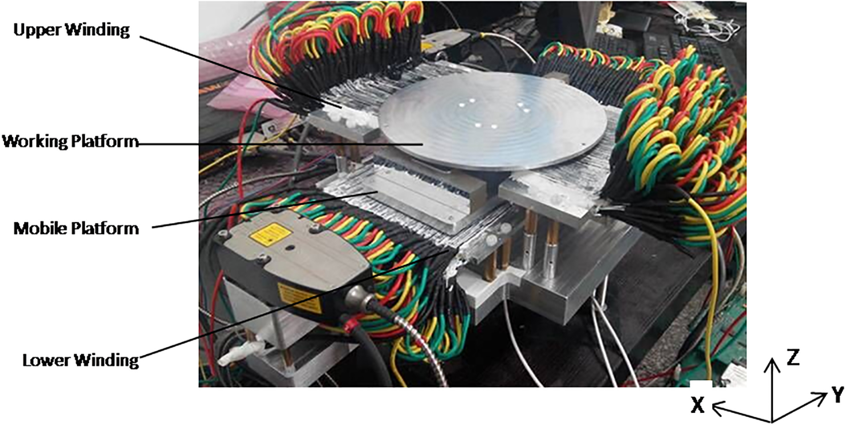
The maglev stage is actuated by the electromagnetic force related to the magnetic field and the three-phase symmetrical current input. In this paper, a mathematical model is developed to describe the linear motor in the sandwiched maglev stage. Finite element analysis can visualize electromagnetic phenomena and help grasping changing rule of working forces, which makes a reference guide to the positioning control. In addition, comparison of levitation forces in both sandwiched maglev stage and ordinary maglev stage is done, in the working range of platform.
Mechanical structure of maglev stage
As shown in Fig. 3, Halbach permanent magnet arrays in
Structure and sketch map of the moving plate.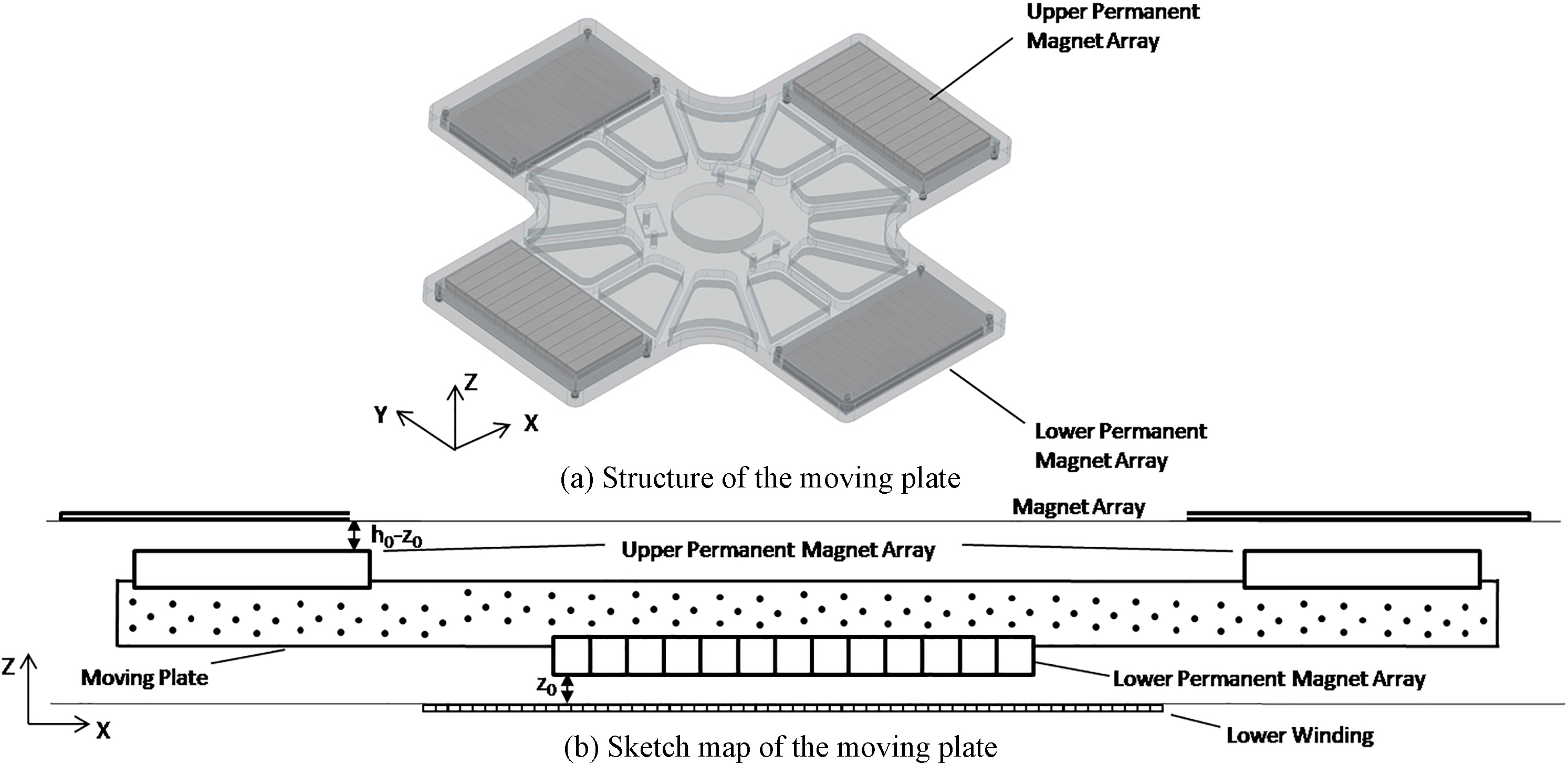
Stress analysis diagram of the moving plate.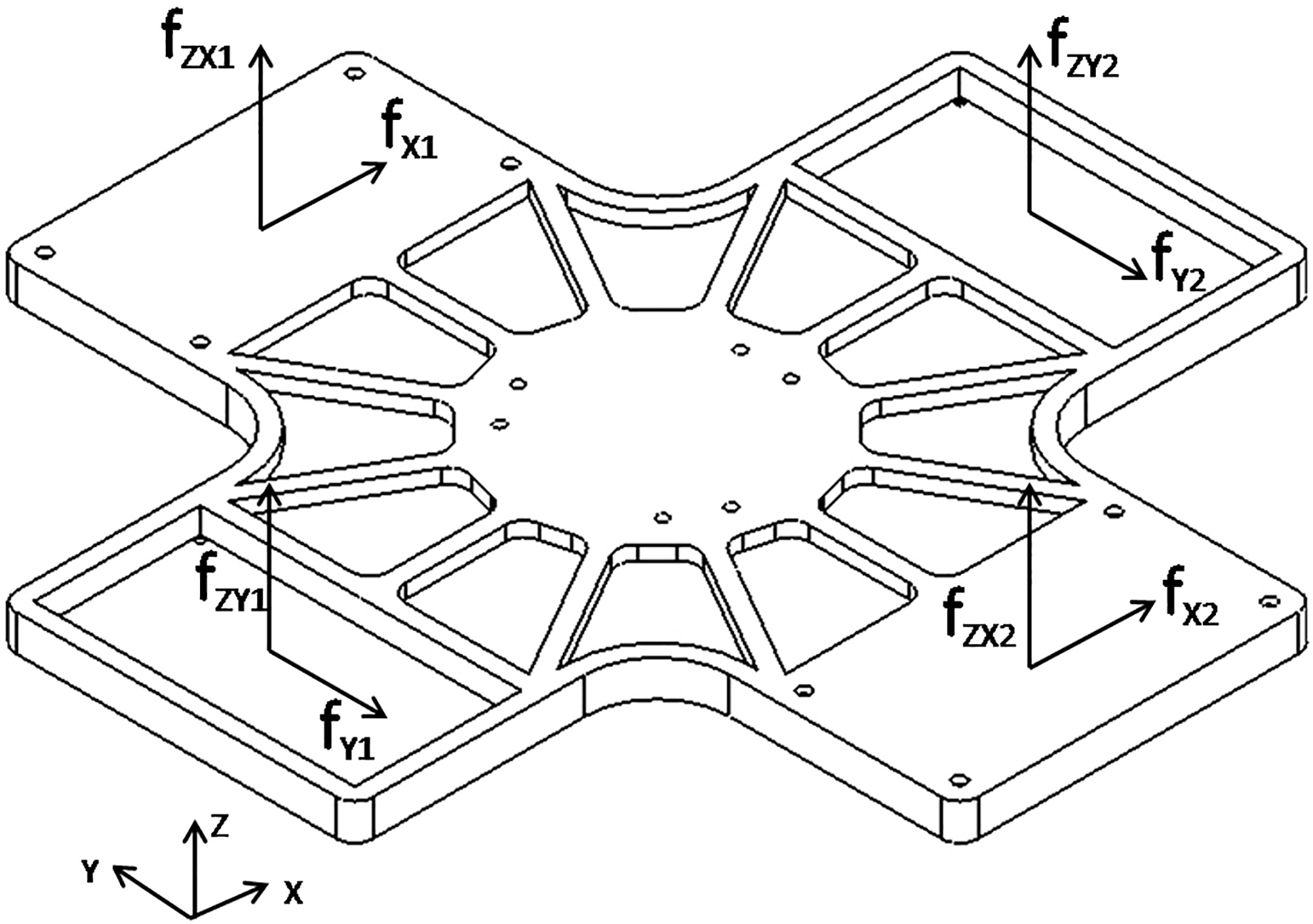
Similarly, Halbach permanent magnet arrays in
Repulsive linear motor composed by Halbach permanent magnet array in one magnetic cycle and the corresponding plane coil is modeled in Fig. 5. The distance from lower stator winding to the working surface of lower magnetic array is
Repulsive linear motor model.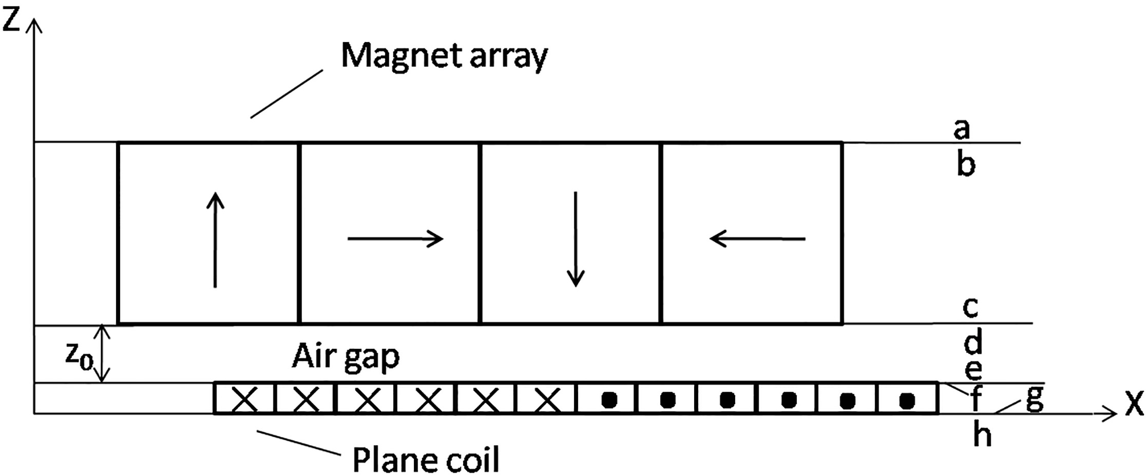
To simplify the model of linear motor, assume all physical constants are homogeneous and end effect is neglected. Executed Maxwell’s equations [10] on this model, magnetic field solution can be achieved at surfaces of magnet array and plane coil. Ignoring higher harmonic of current density, according to Maxwell stress tensor method [10], the working forces on repulsive linear motor can be described in Eq. (1). In the same way, Eq. (2) can be obtained, which describes the working forces on attractive linear motor.
Where:
The levitation force is composed of attractive force
The Taylor series expansion in the bracket of Eq. (5) about operating point
The last right term of Eq. (6) is the higher-order term of Taylor expansion, which is exponentially small enough to be omitted. In this way, terms in the bracket of Eq. (5) can be a constant approximately. In other words, levitation force worked on the moving plate
The forces acted on the maglev stage are analyzed above. According to the feature of sandwiched structure and Maxwell stress tensor method, the relation among working forces, displacement and three-phase symmetry current is given in the form of formula. The stable of levitation force is verified on the mathematics level, which will be described more detailed in the following chapter.
Comsol model of magnetic array
The finite element model of Halbach magnetic array is conducted in Comsol, as shown in Fig. 6. And Fig. 7 shows the distribution of strengthened magnetic field in the vertical direction
Sketch map of magnetic array.
Distribution of magnetic array’s magnetic field on 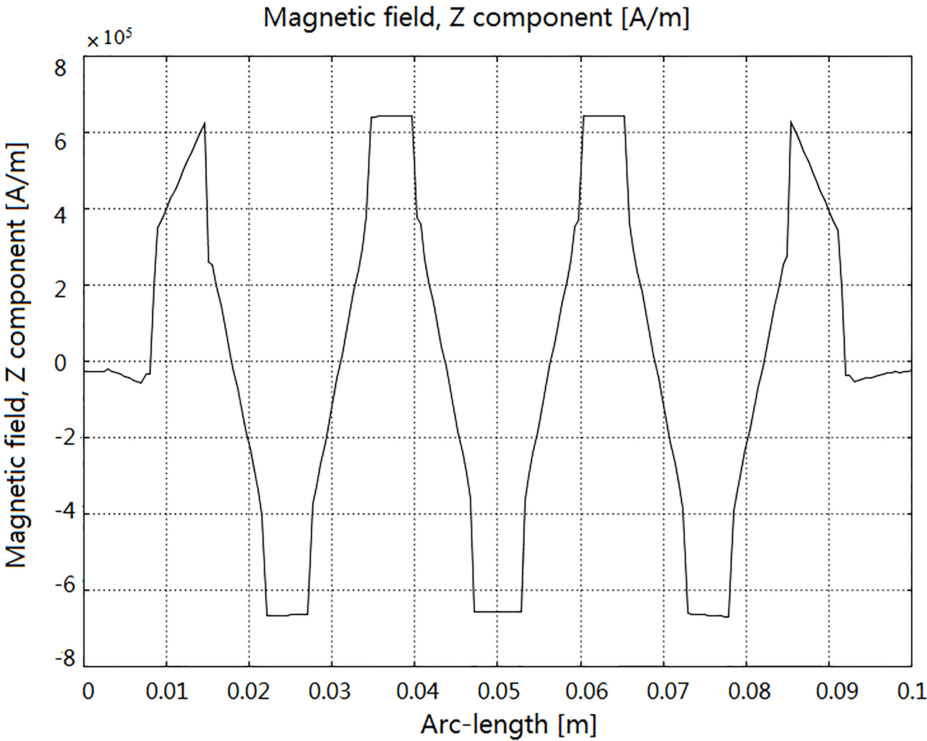
Plane coil is consisted of 60 copper wires, the adjacent two wires compose one phase. The Comsol model of plane coil is constructed as in Fig. 8. The stator winding needs three-phase symmetrical current as follows,
Sketch map of plane coil.
Figure 9(a) shows the distribution of plane coil’s magnetic field on
Distribution of plane coil’s magnetic field on 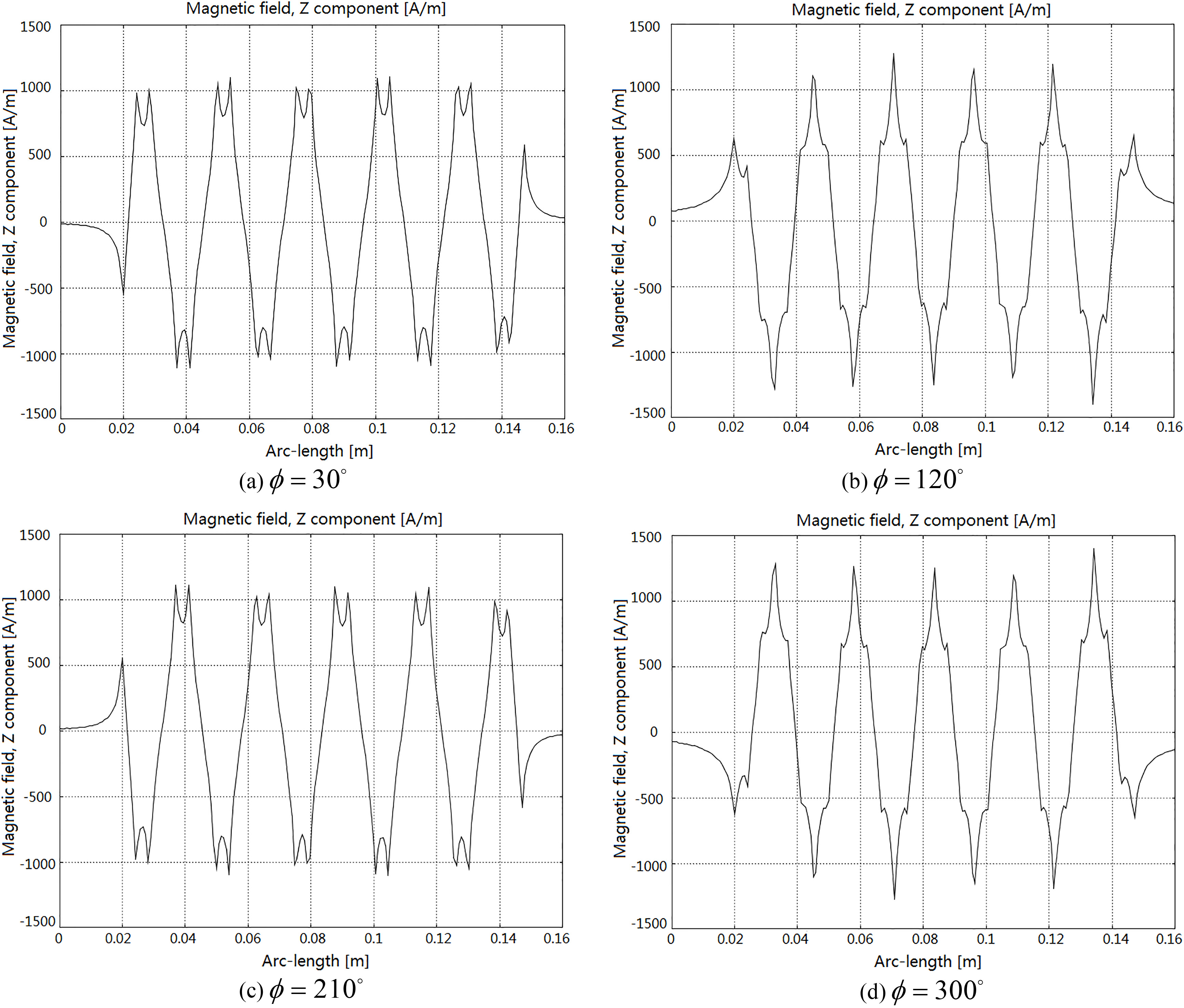
Figure 10 shows the Comsol model of linear motor, composed by one magnetic array and one stator winding, with a gap of 0.5 mm. The dotted line shows the superposition of the starting point of magnetic array’s first magnetic field and the starting point of plane coil’s second magnetic field. When input current with
Sketch map of linear motor in Comsol.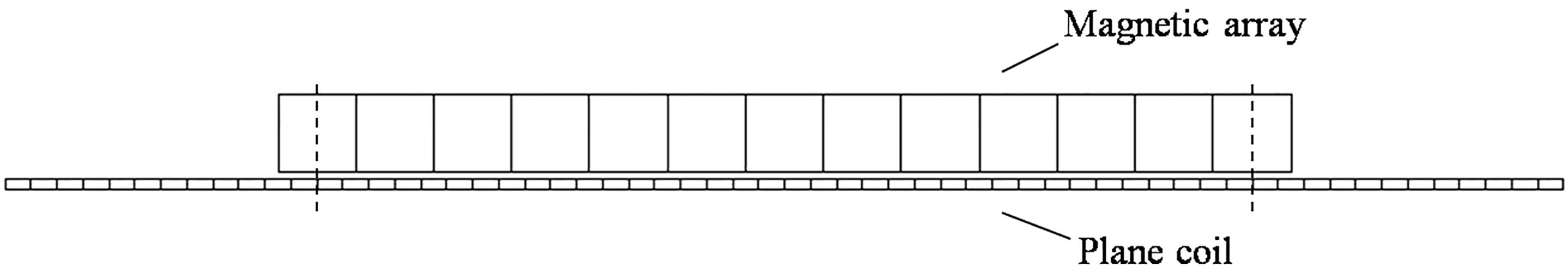
Distribution of Lorentz force density.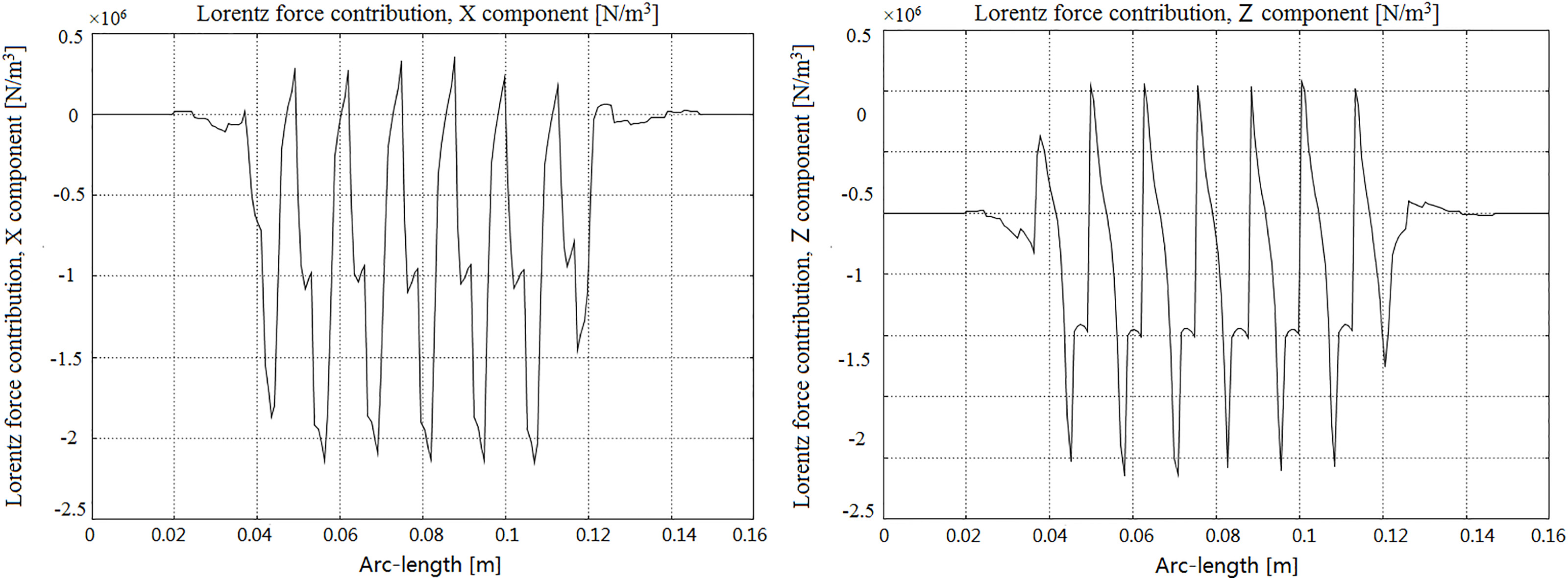
Under the above premises, vary
Force of plane coil.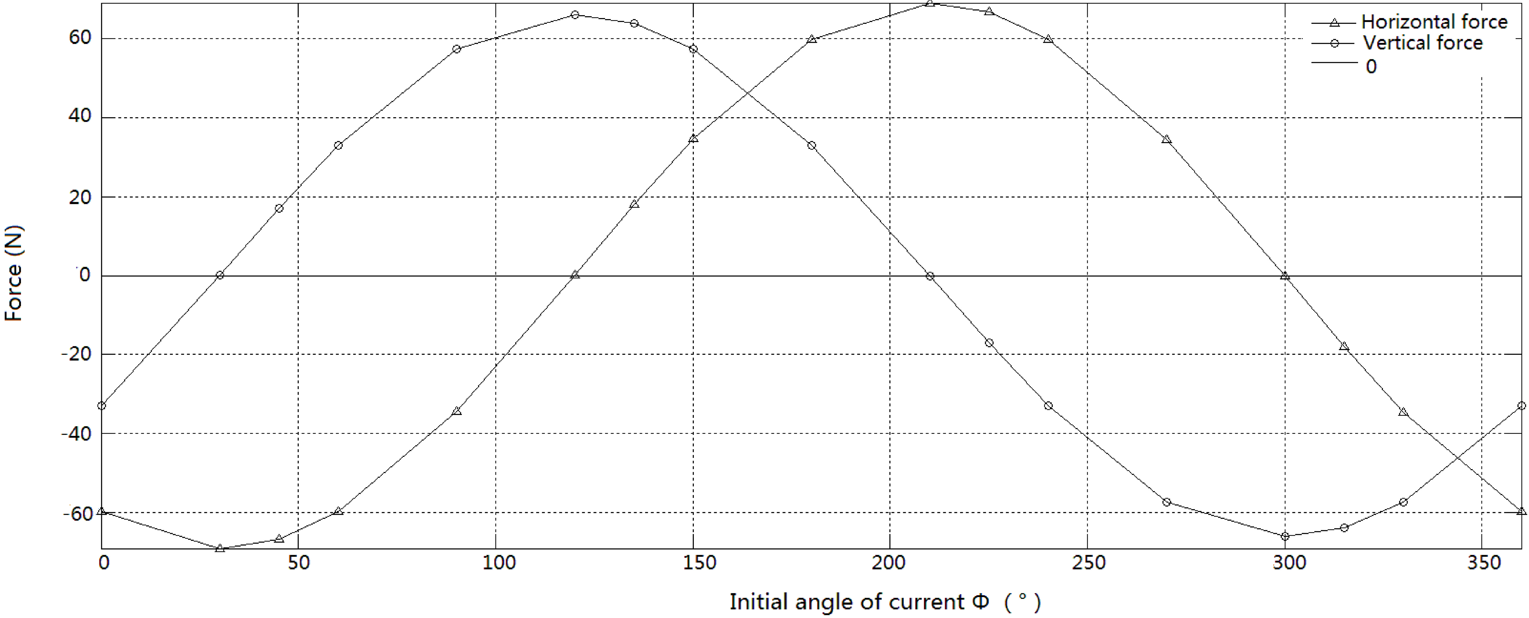
From the analysis, it can be known that when the platform is fixed in one place, different levitation force and driving force can be get, whose value and direction change as the trigonometric function, if current with different
When the platform, or magnetic array, moves to one position (
Comparison diagram of linear motor at specified location.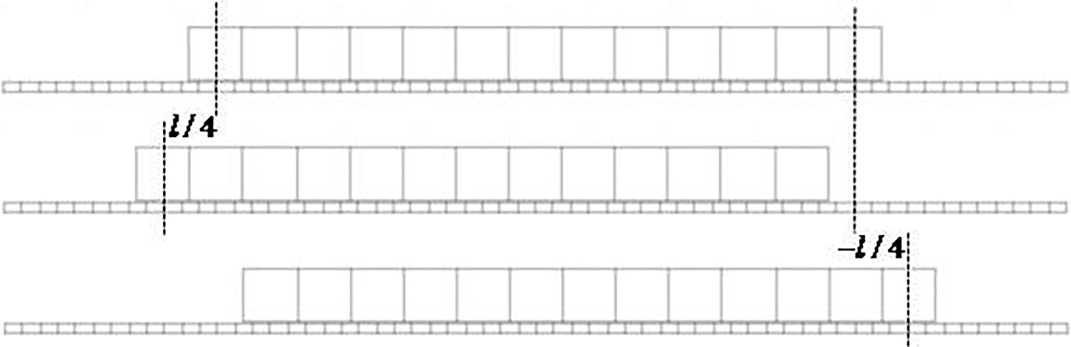
The distribution of magnetic array and stator winding with different current is visualized in this chapter. Based on the above work, the finite element model of linear motor of maglev stage is constructed and three-phase symmetrical current with different parameter is input. In this way, changing trend of working forces can be achieved, which can be described in trigonometric function. Also, value range of
The force analysis can provide method to the control of maglev platform: each time the controller output current, the parameter
Initializing
At the initializing of the platform, a located block is needed to help the platform located in a certain position to get
Positioning control
In positioning control, by implementing feedback control on the desired position and the actual position, needed levitation force and driving force can be obtained. Here , define
Control flow chart.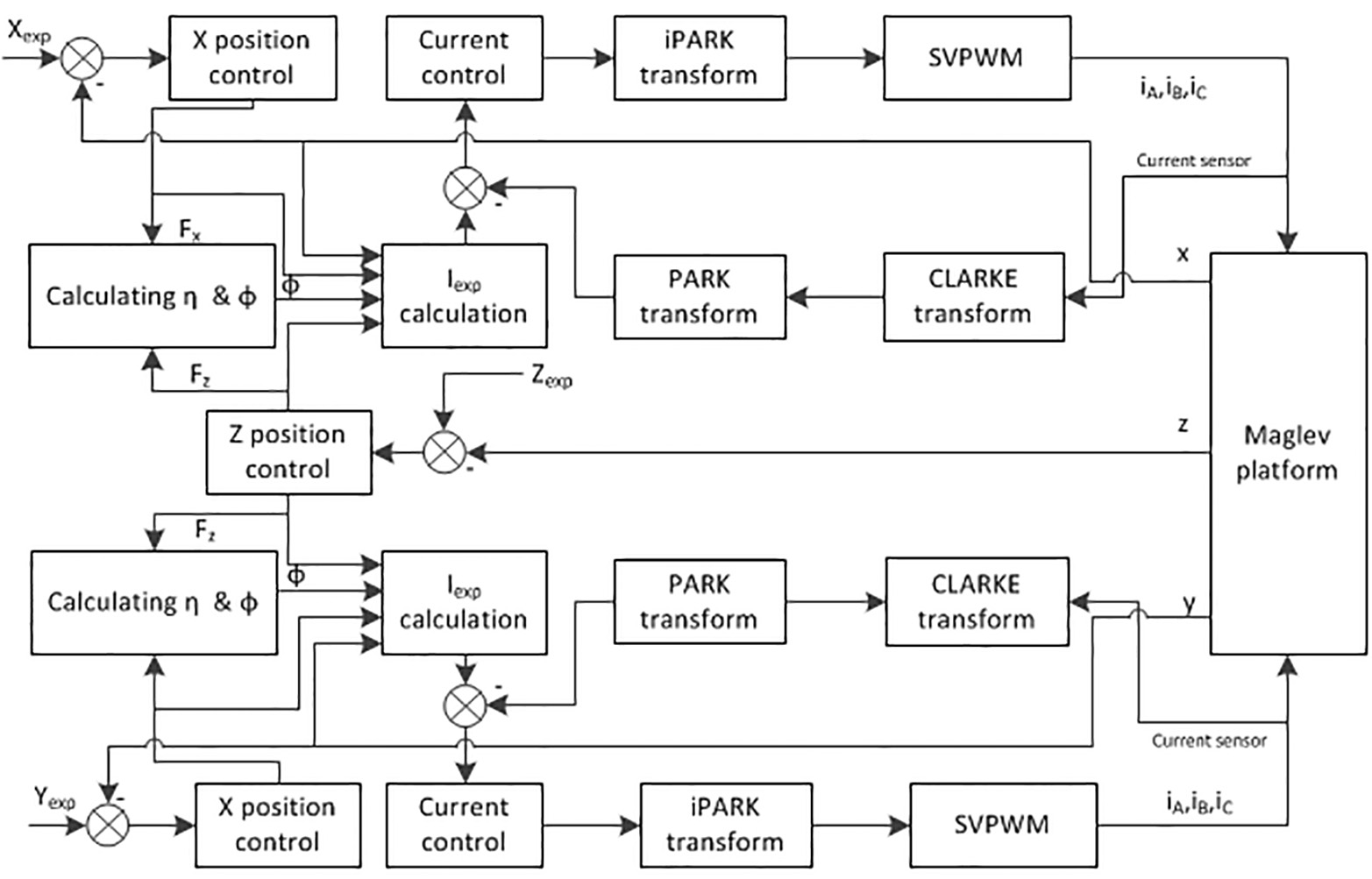
Based on the above analysis of working force, the parameter of current at maglev stage’s initializing is determined. To realize the positioning control, parameter
The simplified model with only magnetic arrays and plane coils of sandwiched maglev stage and ordinary maglev stage model are constructed in Comsol shown in Fig. 15. In ordinary maglev stage model, the four plane coils are arranged in the same surface. Since the air gap varies from 0.4 mm to 0.6 mm, the magnetic array’s position is changed to simulate this variation. Both model are input the same constant current, and values of the total vertical force are collected.
Comsol model of maglev stage.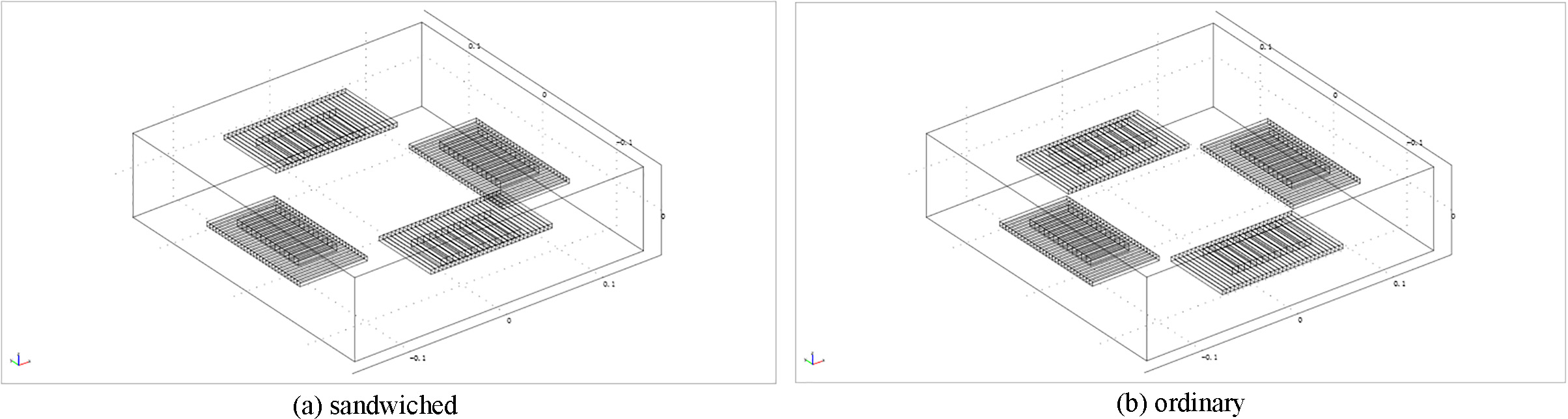
Figure 16 is the comparison of total vertical force, where line with circle, nearly a straight line, represents the sandwiched maglev stage’s and line with triangle, obviously with a slope, represents the ordinary maglev stage’s. It shows that in ordinary maglev stage, the levitation force the platform received has a large variation range, and the higher the platform levitate, the smaller the levitation force is, which is bad to the stable levitation and work. But in sandwiched maglev stage, this phenomenon can be avoided as shown in Fig. 16. No matter whether the air gap is getting bigger or smaller in the working range, the levitation force remains almost unchanged.
Comparison of total vertical force of two types of maglev stage.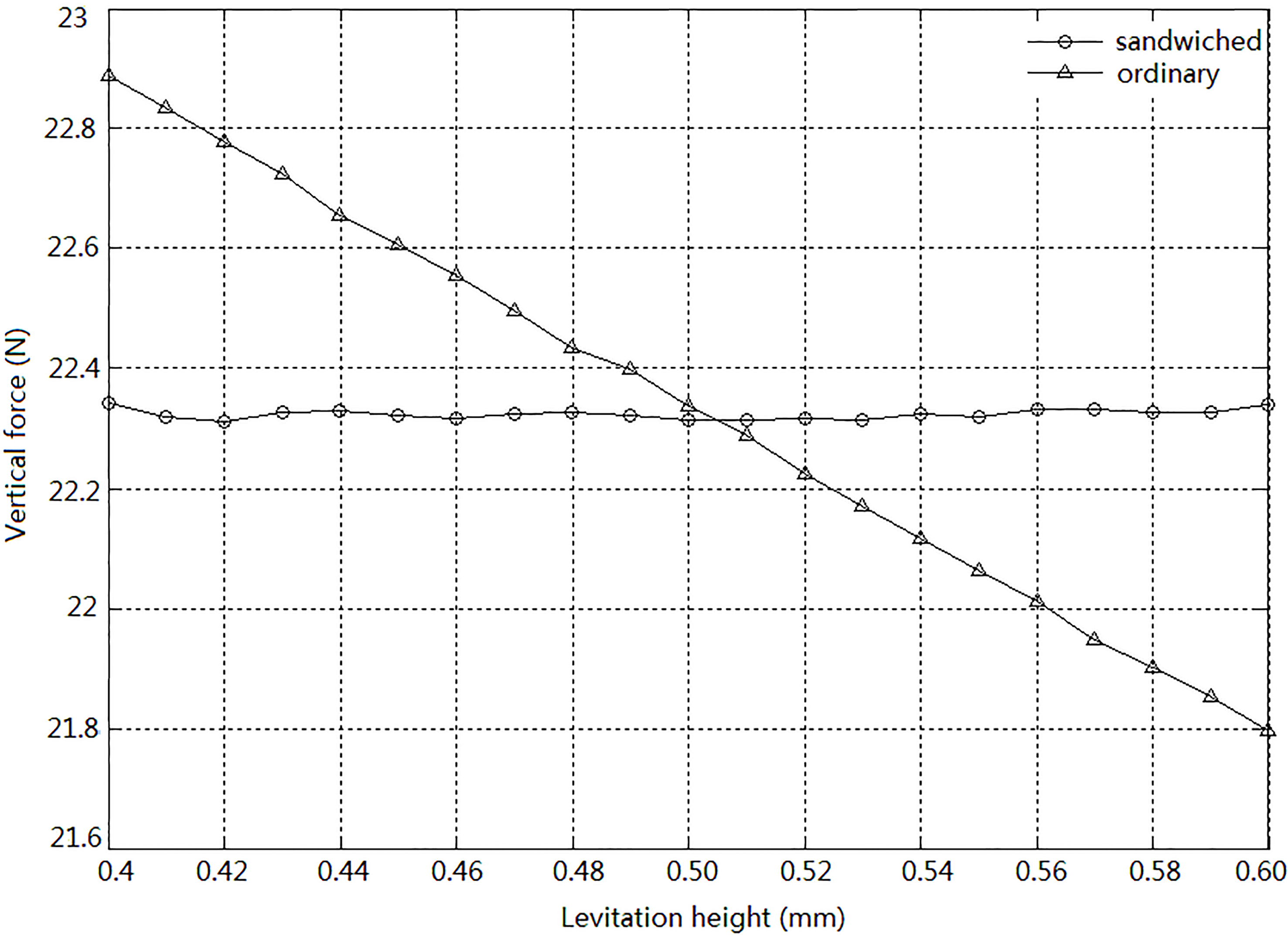
Obviously, this comparison verifies that sandwiched maglev stage has a better performance in stable suspension, which fits with the numerical analysis in Chapter 2.2.
The presented force equations and finite element model show that the sandwiched maglev stage can overcome the exponential relation of levitation force and the suspension height. The sandwiched maglev stage can keep stable within an acceptable range, providing a better levitation ability. The finite element model clearly visualize the magnetic field distribution of magnetic array and stator winding with different currents. It also shows the variation tendency in trigonometric function of working force, which determine the range of current’s parameter value and contribute to the control strategy. According to the working forces’ changing trend, a coefficient
Footnotes
Acknowledgments
This work was supported by National Natural Science Foundation of China (No. 51375052).