
Abstract
For a non-contact piezoelectric motor modulated by electromagnetic field, the equation of the free vibration for the driving system of the motor is given. Using the boundary conditions and continuity conditions, the natural frequencies and mode functions of the driving system are obtained. The variation law of the natural frequency is investigated, when the system parameters of the driving system are changed in a certain range. The results show that the change of the system parameters of piezoelectric stacks and driving beams has obvious effects on odd order natural frequencies of the driving system; the change of the system parameters of the center shaft have obvious effects on even order natural frequencies; In the odd order modes, the maximum vibration amplitude of the driving system occurs at the junction of the driving beam and the center shaft. It is conducive to output of the motor rotation angle. All the results are useful for design and control of operating performance of the motor.
Introduction
According to the contact state of the stator and rotor, the piezoelectric precision actuator can be divided into contact and non-contact [1, 2, 3]. There is friction between the stator and the rotor of the contact piezoelectric actuator, so this type of actuator is not suitable for working a long time, because of the serious wear of the contact surface between the stator and the rotor. Therefore, the contact type piezoelectric actuator has the disadvantages of short life and low reliability [4, 5]. To overcome the disadvantages of the contact type piezoelectric actuator, in 90s of last century, the non-contact piezoelectric actuator is proposed. This type of actuators between the stator and rotor is non-contact or indirect contact, so it has a long life, and no self-locking phenomenon [6]. At present, the driving principle of the non-contact type piezoelectric actuator mainly is based on ultrasonic levitating and electrorheological fluid modulation [7, 8]. With these principles, many applications have been proposed and fabricated [9, 10]. The ultrasonic levitating piezoelectric actuator has the characteristics of high speed and low output torque. However, the most attractive feature of the piezoelectric actuator is the low speed and large torque is lost, and the application field of this kind of motor is limited. Another type of non-contact piezoelectric motor which is modulated by electrorheological fluid has the characteristics of high output torque and high resolution [11]. However, using the electrorheological fluid as the clamping medium, the difficulty to design a wide speed range motor is increased, because of the long response time and poor controllability of electrorheological fluid [12, 13].
To solve the above problems existing in the non-contact piezoelectric drive system, we propose a novel non-contact piezoelectric motor modulated by electromagnetic field. The motor mainly consists of a stator (electromagnetic coupling mechanism), a rotor, driving mechanism and two piezoelectric stacks, as shown in Fig. 1. There are two short beams in the driving mechanism. One end of each beam is connected with the frame through a flexible hinge; the other end is fixed on the center shaft. Two piezoelectric stacks are mounted on the driving mechanism to bend short beams respectively. As soon as the piezoelectric stacks are excited by a sinusoidal signal, and the stator is swung. Then, the rotor modulated by the electromagnetic coupling mechanism, which is controlled by square wave signal, can rotate one step by one.
However, the free vibration analysis for driving system of the motor has not been investigated yet. It is unfavorable to design the motor structure size and choose the system parameters. In this paper, the structure and working principle of the motor is presented. The dynamics equation of driving system is proposed. Using the boundary conditions and continuity conditions, the natural frequencies and mode functions of the driving system are obtained. The effect of system parameters on the structural design is investigated. All the results are helpful to design a high-performance non-contact piezoelectric motor.
The non-contact piezoelectric motor modulated by electromagnetic field.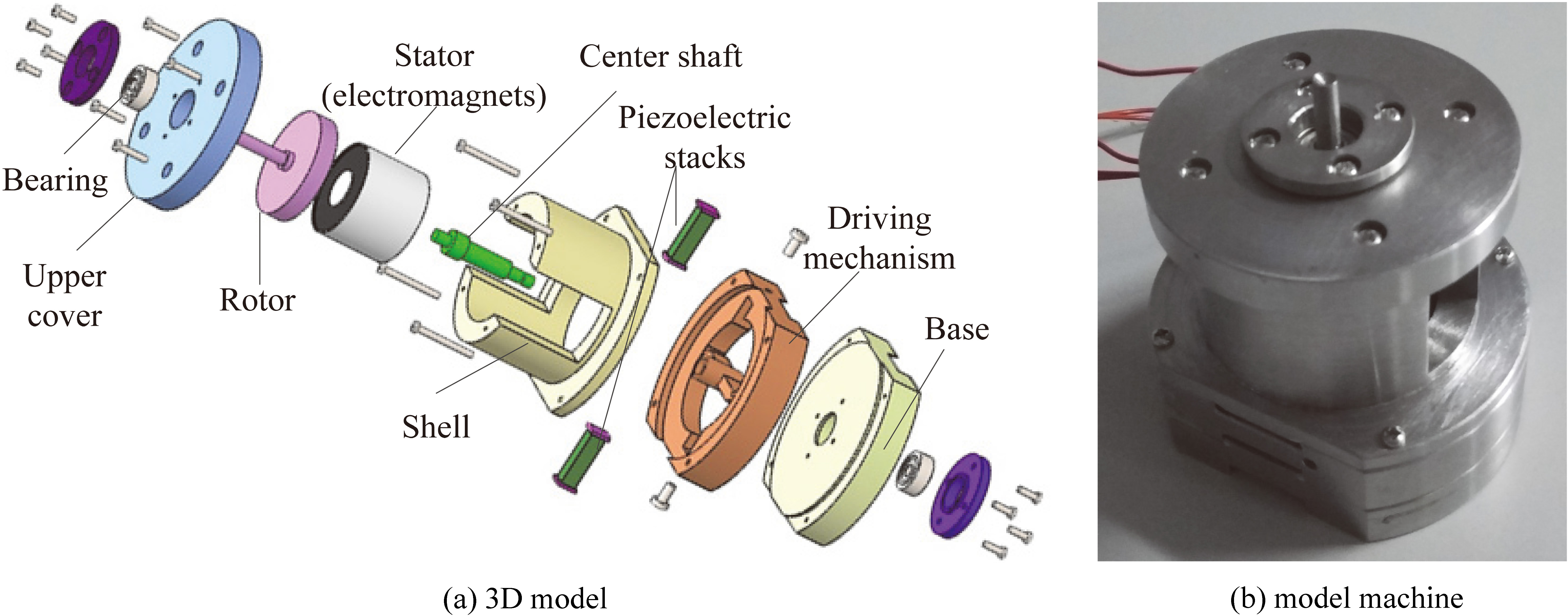
Schematic sketch of driving principle.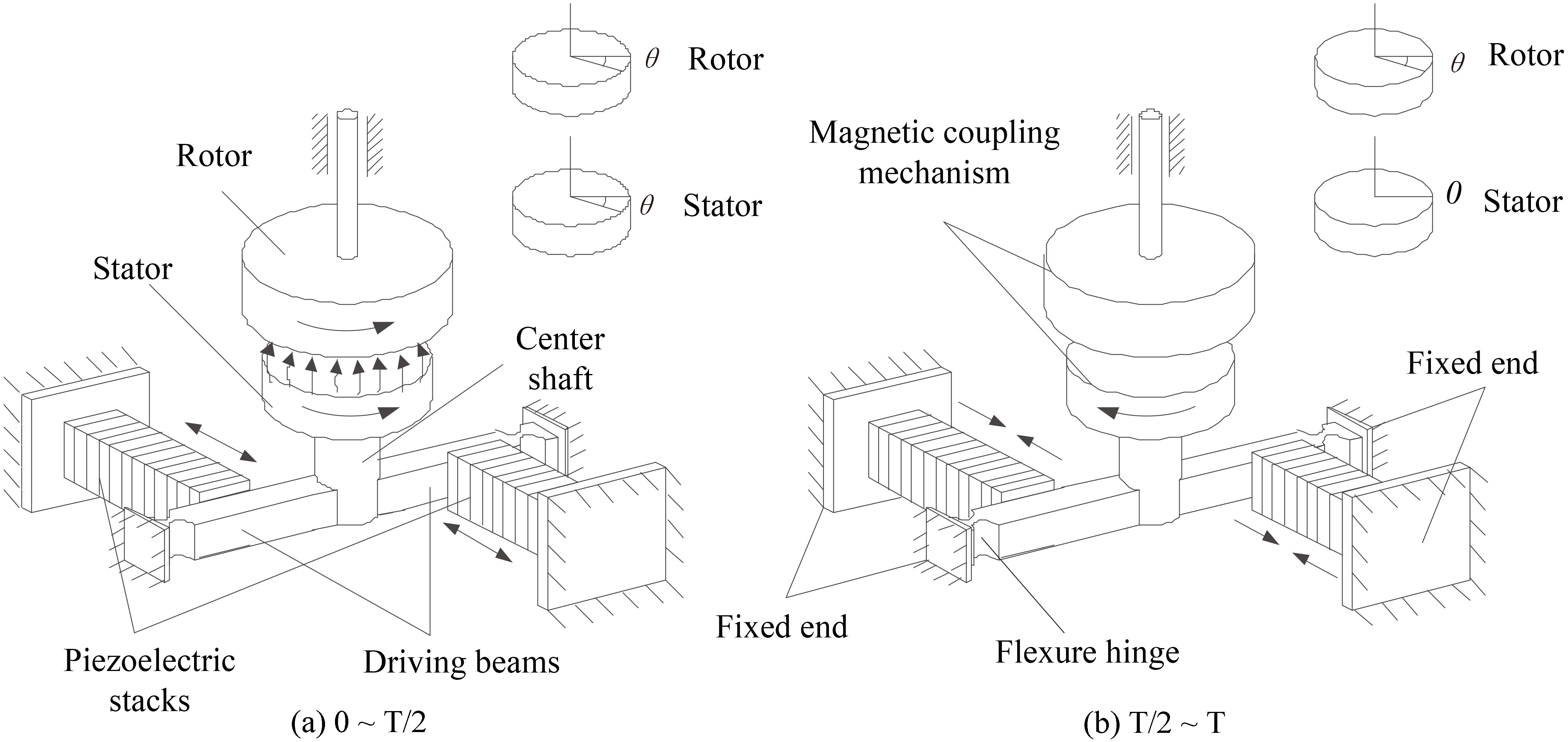
Driving signal diagram.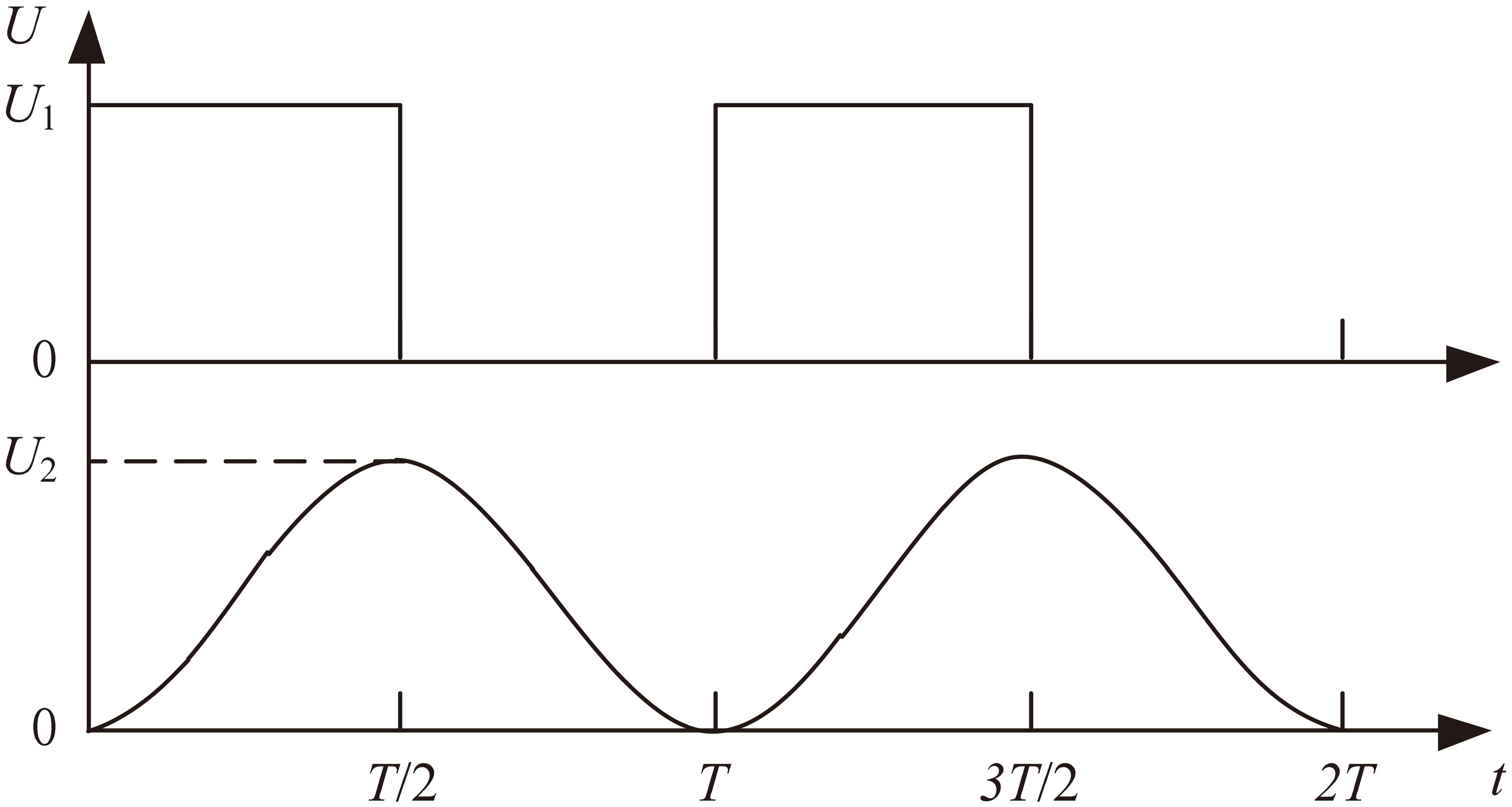
The driving system is extracted from the motor. They are composed of a stator, two driving beams, two piezoelectric stacks and center shaft, as shown in Fig. 2. The working procedure of the motor is as follows:
As shown in Fig. 3, the sine signal is supplied in two piezoelectric stacks, and the square wave signal is supplied in the stator (electromagnetic coupling mechanism). When the drive voltage signal is in 0 When the drive voltage signal is in
Dynamic model
For establishing the dynamic model of the motor to solve the natural frequencies and mode functions, it is necessary to simplify the motor structure. Therefore, the dynamic model of the continuous elastic system is established by considering the longitudinal deformation of the piezoelectric stack, the bending deformation of the driving beams and torsional deformation of the center axis. Moreover, the simplified dynamic model is based on the following assumptions:
Schematic sketch of dynamic model.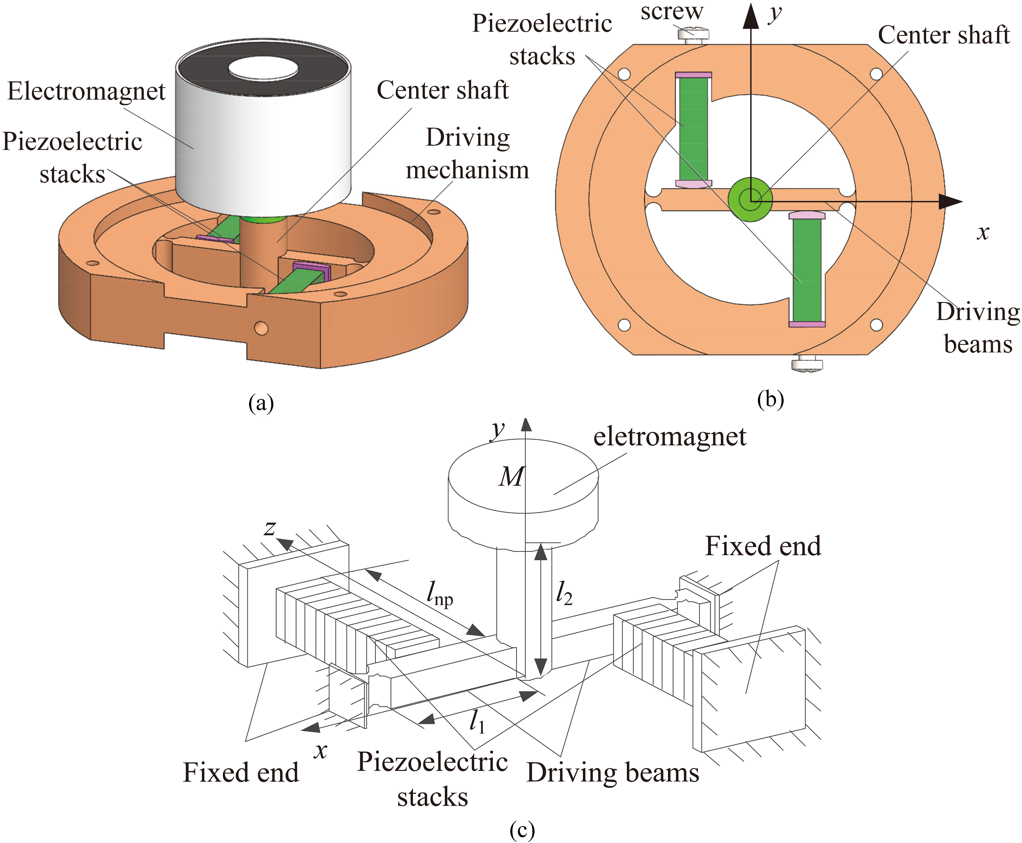
As shown in Fig. 4, the length of two driving beams is less than 5 times the height of cross section. So they are considered Timoshenko beams. There is a flexible hinge in the driving beam end. Its tensile deformation is ignored; the flexure hinge is simplified for the combination of a hinge with a coil spring, which stiffness is
where The electromagnet is simplified into a mass block and is mounted the upper end of the center shaft; the lower end of the shaft is fixedly connected with the ends of the two driving beams.
As shown in Fig. 5, the local coordinate system of a piezoelectric stack is established. Piezoelectric stacks are made by bonding multilayer piezoelectric ceramic sheets. Here, we consider the piezoelectric stack as a continuous system, and ignore the energy loss between the layer and the layer. We also consider the charge cannot be generated by the preload. The effect of preload force on the dynamic model is ignored. The vibration direction of the piezoelectric stack is only longitudinal.
The dynamic model of a piezoelectric stack.
From the model, the dynamics equation of the piezoelectric stack micro unit can be given as follows
where
Using the piezoelectric equation, the internal force can be given as [14]
where
where
Let
where
The driving beam is divided into two sections. In order to obtain the equal amplitude oscillation of the electromagnetic coupling mechanism, we designed the driving beam as a symmetrical structure about the axis of the central axis, so the two beams are equal
The dynamic model of the driving beams.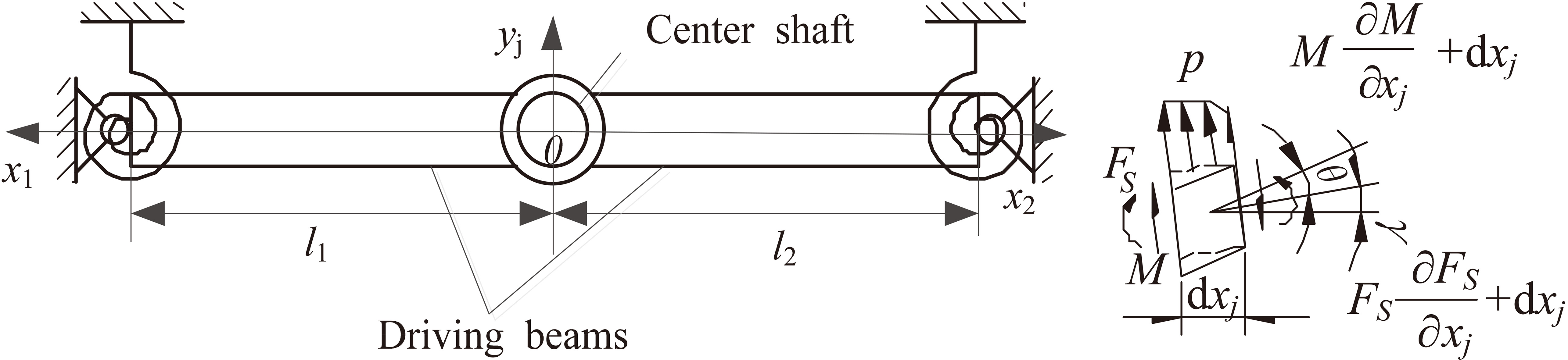
Considering the driving beam as a Timoshenko beam, the dynamic equation of the bending vibration of the beam can be given as follows
where
Let
where
Thus, the general solution of Eq. (8) is given by
where
With the coupling end of the central axis and the driving beam as the origin, the local coordinate system is established.
where
The dynamic model of the center shaft.
From the model, the dynamic equation of the center shaft can be described as follows
Substituting Eq. (10) into Eq. (11) yields
where
Let
where
As a continuous system, the relation of each component should be in accordance with the boundary conditions, force balance conditions and the deformation compatibility conditions as follows:
When
The end of the driving beams is considered as the combination of a hinge with a coil spring. So the displacement response of the ends is 0, and the moments of the ends are equal to the negative product of the ends angle and the stiffness of the flexible hinge. The boundary conditions of displacement and rotation are as follows
The parameters of the piezoelectric stack
Mode 1.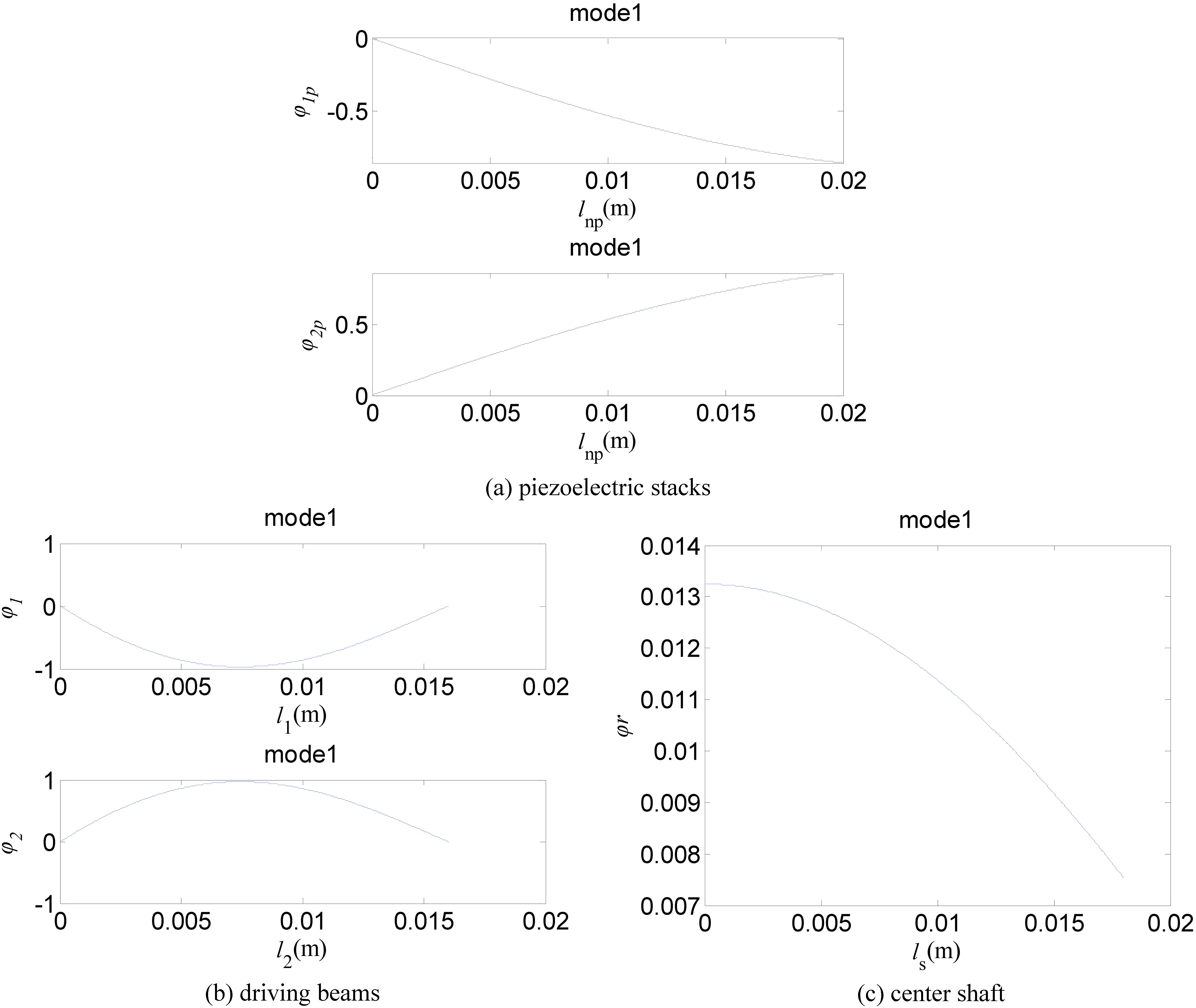
At the coupling point of a piezoelectric stack and s driving beam, the longitudinal displacement of the piezoelectric stack is equal to the bending displacement of the driving beam, and the output force of the piezoelectric stack is equal to the shear force of the beam. Thus
where
There is a mass on the upper end of the center shaft. So the upper end torsion of central shaft is equal to the torsional inertia force of the mass. Thus, the boundary conditions is
The parameters of the driving beam
Mode 2.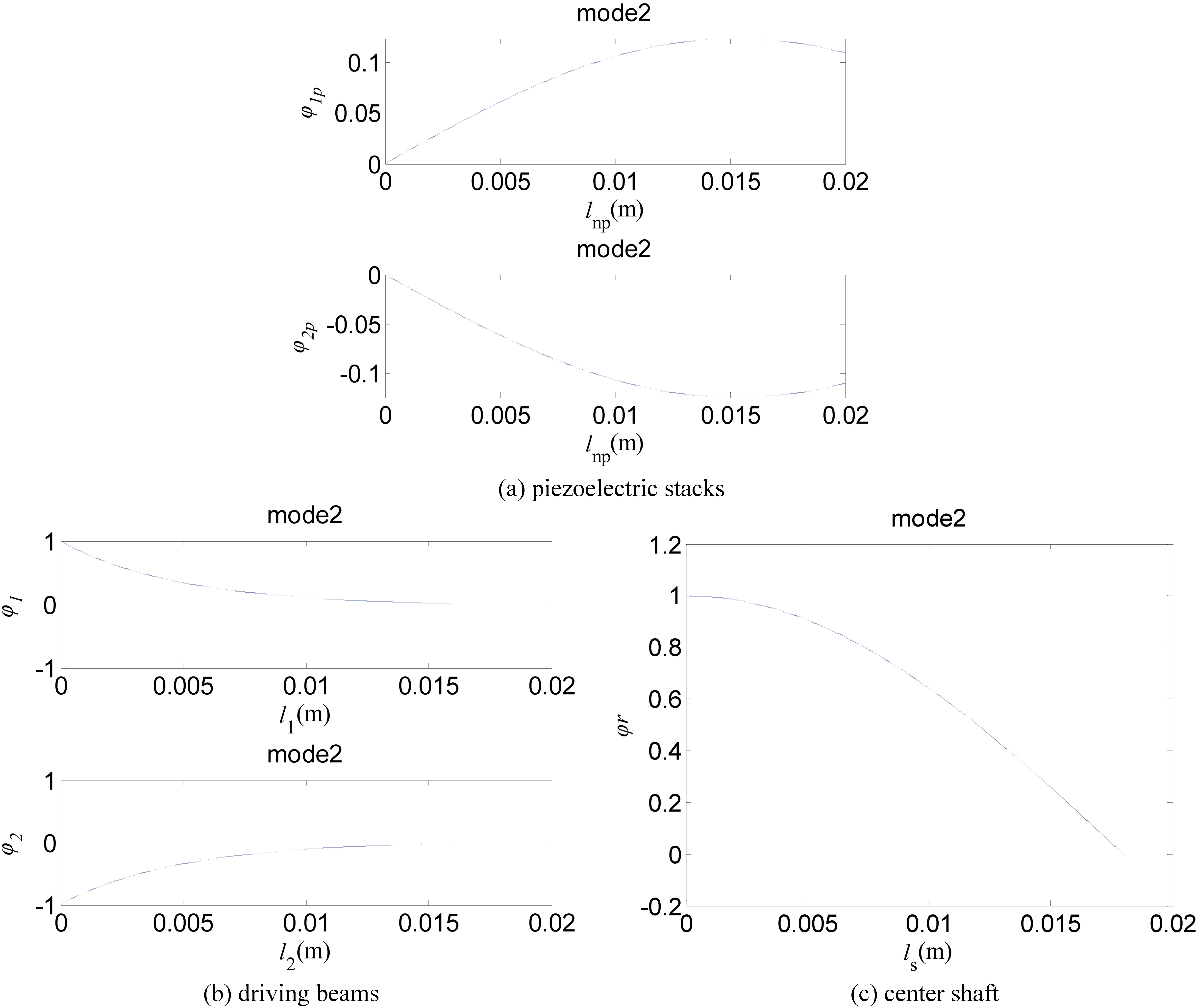
where
The lower end of the center shaft is coupling with the driving beams. Because the lower end face of center shaft is free, the torsion is 0. But the torsional linear displacement of the lower shaft is equal to the lateral displacement of the junction of the driving beams and the center shaft. Thus, the boundary conditions is
The coefficients
The parameters of the electromagnetic coupling mechanism
Natural frequency of the driving system (rad/s)
Mode 3.
Mode 4.
Mode 5.
Modal analysis
Spring steel is chosen as the material of the driving system, and the other system parameter is listed in Tables 1–3. The equations of the boundary conditions are utilized for the free vibration analysis of the driving system to obtain the natural frequencies. By substituting these natural frequencies into Eqs (4), (9) and (13), the vibration modes of the driving system can be obtained. Table 4 lists the first eight natural frequencies, and the first six vibration modes are shown in Figs 8–13. From the results of the natural frequencies and vibration modes, we can obtain the first eight natural frequency of the driving system increase with the increase of the orders. Especially, the linear degree is remarkable in the even order natural frequency.
In the odd order modes, the amplitude of driving beams is relatively large, and the amplitude of the center shaft and pizoelectric stacks is relatively small. With mode order of driving system increases, the peak number of the mode function of each subsystem increases. Therefore, when the excitation frequency is close to odd order natural frequency, the vibration of the driving beams is easy to occur.
In the even order modes, the amplitude of the center shaft is relatively large, and the amplitude of the driving beams and piezoelectric stacks is relatively small. With mode order of driving system increases, the peak number of the mode function of the center shaft and piezoelectric stacks increases, but the change of the driving beam is not remarkable. The maximum amplitude of the vibration of the driving system occurs at the junction of a drivding beam and the center shaft. Therefore, when the excitation frequency is close to even order natural frequency, the vibration of the center shaft is easy to occur.
Sensibility analysis
The effect of system parameters on the inherent characteristics is necessary to be investigated, because this effect can provide a theoretical basis for the design and parameter selection of drive system. Here, five kinds of different materials are selected to make the drive system. Using the dynamic equation of the driving system, the first three natural frequencies can be obtained, and the results are shown in the Table 5. As seen, in the 5 kind of materials, the first-order natural frequency of alloy steel is lowest. The second-order and third-order natural frequency of brass is lowest. In the first-order natural frequency, the brass and the spring steel is closer; in the second-order natural frequency, the aluminium alloy, alloy steel and spring steel is closer; in the third-order natural frequency, the alloy steel and spring steel is closer.
The first – three natural frequency of different materials
The first – three natural frequency of different materials
Mode 6.
Changes of natural frequencies with respect to various parameters.
Spring steel is chosen as the material of driving system. When the system parameters are changed in a certain range, the change curves of the natural frequencies are shown in the Fig. 14. From the Fig. 14, the following observations were worth noting.
When the parameters of the piezoelectric stacks ( When the length of the driving beams ( When the width of the driving beams ( When the thickness of driving beams ( When the contact position of the beams and the piezoelectric stack ( When the length of the center shaft (
The diameter of the center shaft (
A non-contact piezoelectric motor modulated by electromagnetic field is proposed. The dynamics equation of the driving system of the motor is presented. Then, the natural frequencies and mode functions are obtained. The sensitivities of inherent characteristics to system parameters are investigated. The results show:
The structural parameters and materials of piezoelectric stacks and driving beams have obvious effects on odd order natural frequencies of the driving system. The system parameters of the center shaft have obvious effects on even order natural frequencies. In the odd order modes, the maximum vibration amplitude of the driving system occurs at the junction of the driving beams and the center shaft. It is conducive to output of the motor rotation angle. All the results are useful for design and control of operating performance of the motor.
Notation
Footnotes
Acknowledgments
This project is supported by National Natural Science Foundation of China (51605423).