
Abstract
This paper presents a mathematical modeling of a magneto-rheological (MR) brake to determine a relationship between input current and output torque for applying a variety of control applications. The proposed model is consisted of two sub-models: a mechanical sub-model, using Bingham plastic model for MR fluid and a magnetic circuit sub-model through a semi-empirical method to estimate the nonlinear hysteresis behavior of MR brake used. The first mechanical sub-model using Bingham plastic model describes the magnetic filed dependent fluid characteristics and the relationship between the torque and the dynamic yield stress caused by the applied field. The magnetic circuit makes up the second sub-model with the relationship between the dynamic yield stress and the magnetic induction of MR fluid. Due to the ferromagnetic property of the material used to form the flux path, MR brake experienced hysteresis effects and thus its hysteresis behavior is approximated through a semi-empirical method. The final model of MR brake links both sub-models together by the torque. An experimental setup is manufactured to evaluate the proposed model with a commercial MR brake used. The experimental result is compared with these predicted from the proposed nonlinear model in order to validate the model accuracy. The result shows that proposed model is reasonably predicted the hysteresis behaviors of MR brake. Moreover, the frequency response test of MR brake is carried out to evaluate the feasibility for a torque estimator in control use, and shows that the predicted frequency response matches up to the experimental characteristics and MR brake used has a bandwidth of nearly 35 Hz enough high to control.
Keywords
Introduction
Magneto-rheological (MR) fluids belong to the class of material known as controllable fluids, such as electro-rheological fluids and ferrofluids, which respond to applied magnetic field with fast, continuous, and reversible change in their rheological behavior. Typically, this change can be characterized by the development of yield stress that monotonically increases as the strength of an applied magnetic field increases. The response of MR fluids results from the polarization induced in the suspended particles by application of an external field. The interaction between the resulting induced dipoles causes the particles to form columnar structures, known as chain-cluster structure, parallel to the applied field [1]. The structures restrict flow of the fluid or the relative motion between two discs. The energy needed to yield these structures increases as the applied field increases in a field dependent yield stress. The field dependent yield stress makes possible numerous industrial applications, such as fluid clutches [2], semi-active suspension [3], vehicle brake [4, 5], MR valve [6], seismic damper [7, 8], and exercise machines [9, 10, 11, 12]. Furthermore, a research has focused on the development of a hybrid actuators that are coupled with conventional pneumatic actuators to enable low cost position and velocity control [13]. In past years, MR brakes have been available for a wide variety of application to overcome some of the disadvantages of DC motors, such as motor inductance limiting the rate of change of motor current and motor back e.m.f influencing motor current, and mainly replaced as a form coupled to a conventional rotating actuator via an MR brake. Using an MR brake, it is possible to give very smooth and continuous control and realize a high bandwidth novel actuator.
Brookfield and Dlodlo modeled an ER actuator as a rotary actuator through a linear transfer function between the applied field and the torque, and developed a PID based torque controller to mitigate nonlinear characteristics [2]. Zhou et al. proposed a novel MR fluid brake with high transmitted torque. To obtain high torque, they adopted a structure with double shearing disks and showed the results obtained successfully through experimental. The results showed the typical hysteresis behavior of MR fluid brake [14]. Kikuchi et al. developed a MR brake to apply an isokinetic exercise system for rehabilitation training [9]. For controller design, a transfer function of ER brake was determined by plotting its amplitude and phase response and used as the transfer function of system. Takesue et al. reported an actuator developed using an MR fluid and investigated the characteristics of the actuator [10]. They also obtained the transfer function from the input current to the output torque base on the Bode diagram of an experimental result. The results showed that MR actuator had a hysteresis loop. MR brake consists of a rotary shaft, disc, housing, an electromagnetic coil and MR fluids. It is known that the magnetic properties of MR fluids vary significantly from the properties of most bulk ferromagnetic properties in that ferromagnetic induction can typically be linearized over a much broader range of applied field [15]. Jolly et al. also experimentally founded that little or no hysteresis can be observed in the induction curves and announced that this super paramagnetic behavior is a consequence of the magnetically soft properties of the iron used as particulate material in these fluids and the mobility of this particulate phase [15]. Nevertheless, materials for forming flux path in MR brake are generally selected by high permeability materials, such as cold-wrought steel, Permalloy and Hiperco 50-A, to have high a magnetic flux. These ferromagnetic materials are characterized by magnetic hysteresis phenomenon that is not covered by the linear equations. The effects of hysteresis behavior can lead to undesired inaccuracies and even instability. Therefore, magnetic hysteresis model incorporated into Bingham model describing MR fluids is needed for many applications in which calculations of magnetic fields are made and plants for which controller are being designed. Also, it is necessary to have a simple model which can be easy implemented a variety of systems.
This paper presents a mathematical modeling of an MR brake to determine a relationship between input source and output torque for applying a variety of control applications. The proposed model is divided into two sub-models. The first mechanical sub-model using Bingham plastic model describes the magnetic filed dependent fluid characteristics and the relationship between the torque and the dynamic yield stress caused by the applied field. The magnetic circuit makes up the second sub-model with the relationship between the dynamic yield stress and the magnetic induction of MR fluid. Due to the ferromagnetic property of the material used to form the flux path, MR brake experienced hysteresis effects and thus its hysteresis behavior is approximated through a semi-empirical method. The final model of MR brake links both sub-models together by the torque. An experimental setup is manufactured to evaluate the proposed model with a commercial MR brake used. The experimental result is compared with these predicted from the proposed nonlinear model in order to validate the model accuracy. The result shows that proposed model is reasonably predicted the hysteresis behaviors of MR brake. Moreover the frequency response test of MR brake is carried out to evaluate the feasibility for a torque estimator in control use, and shows that the predicted frequency response matches up to the experimental characteristics and MR brake used has a bandwidth of nearly 35 Hz enough high to control.
MR brake modeling
The model of the MR brake can be divided into up two sub-models: a mechanical sub-model and a magnetic circuit sub-model. It is see that both sub-models are clearly coupled. For both sub-models, a separate model has been derived, correspondingly, and the procedure will be shown in what follows.
The structure of RD-2087-01 MR brake.
MR fluids are non-colloidal suspensions of polarizable particles having a size on the order of a few microns. MR fluids are created by adding micro-sized iron particles to an appreciate carrier such as oil, water or silicon. MR fluids belong to a class of controllable fluids that respond to an applied field with a dramatic change in their rheological behavior. Their rheological behavior is nearly the same as that of the carrier fluid when no external magnetic field is present. However, when exposed to a magnetic field, the iron particles acquire a dipole moment aligned with the applied magnetic field to form linear chains parallel to field [1]. The structure of RD-2087-01 MR brake used in this study is as shown in Fig. 1. Table 1 shows the specifications of RD-2087-01 MR brake, supplied by Lord Corporation. It is found that the essential magnetic field dependent fluid characteristics of MR fluids can be described by a simple Bingham plastic model [1]. In this model, the total shear stress
where
The first part of the RHS of Eq. (1) produces a torque, which is dependent on the magnetic filed, and the second term generates a viscous torque. Therefore, the output torque equation can be written as
For a given magnetic field distribution, the output torque generated by one MR fluid gap can be obtained by integrating shear yield stress over the plate surfaces as
where
The specifications of RD-2087-01 MR brake supplied by Load Corporation
Where,
Similar steps can be followed to derive the torque produced by MR fluid plastic viscosity,
For MR brake analyzed in this study, considering that the total torque occurs in two sides’ surfaces of the disk, the output of MR brake is given as
For the Binghamplastic model, the MR fluid properties of dynamic yield stress,
The polynomial coefficients were determined by least-squares fit of the dynamic yield stress data as a function of magnetic field from data supplied Lord Corporation, and are:
Assuming no magnetic flux leakage, and according to the principle of Continuity of magnetic flux, namely assuming that the flux of MR fluid equals to that of steel, the magnetic flux density in the steel path,
where
In magnetization curves, the magnetic induction,
Where,
The first and second term of RHS in Eq. (11) presents energy restoring and energy dissipation, respectively. Figure 2 shows the magnetization curve which represents the relationship between
The voltage-current relationship can be easily derived by Kirchoff’s laws:
Magnetization curve showing the relationship between the flux and current.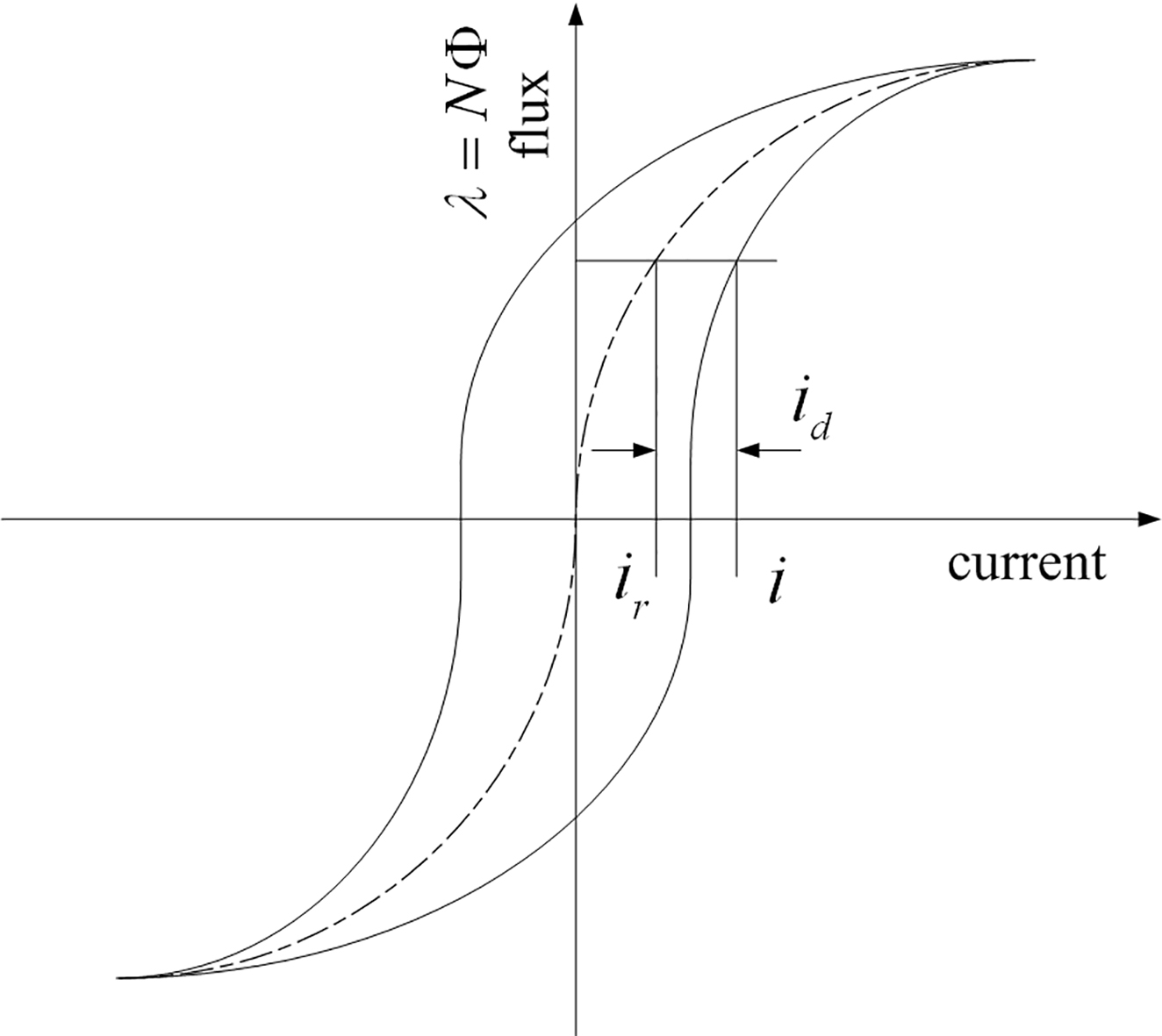
A simplified block diagram of the non-linear model for magnetic circuit is shown in Fig. 3.
A simplified block diagram of the non-linear model for magnetic circuit.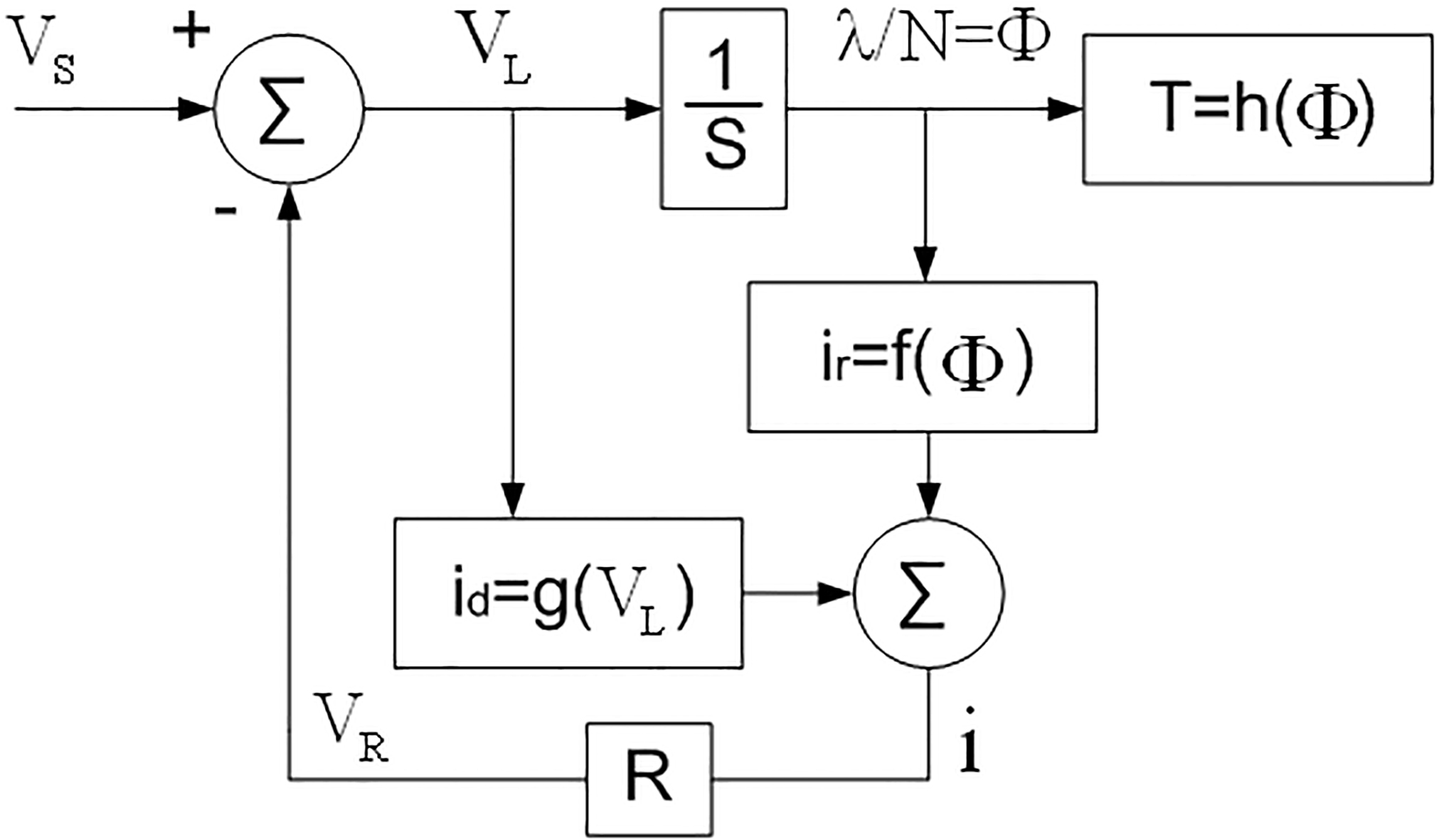
The coefficients of the polynomials estimated by a least squares fit
In order to determine this non-linear model structure of the magnetic circuit for MR brake, some experiments is carried out to identify the model parameters
A simplified block diagram implemented in this study is shown in Fig. 8, which presents relationships between considering energy restoring and energy dissipation terms and MR brake dynamics used in this work.
Measured and calculated results for time when applying a triangular wave.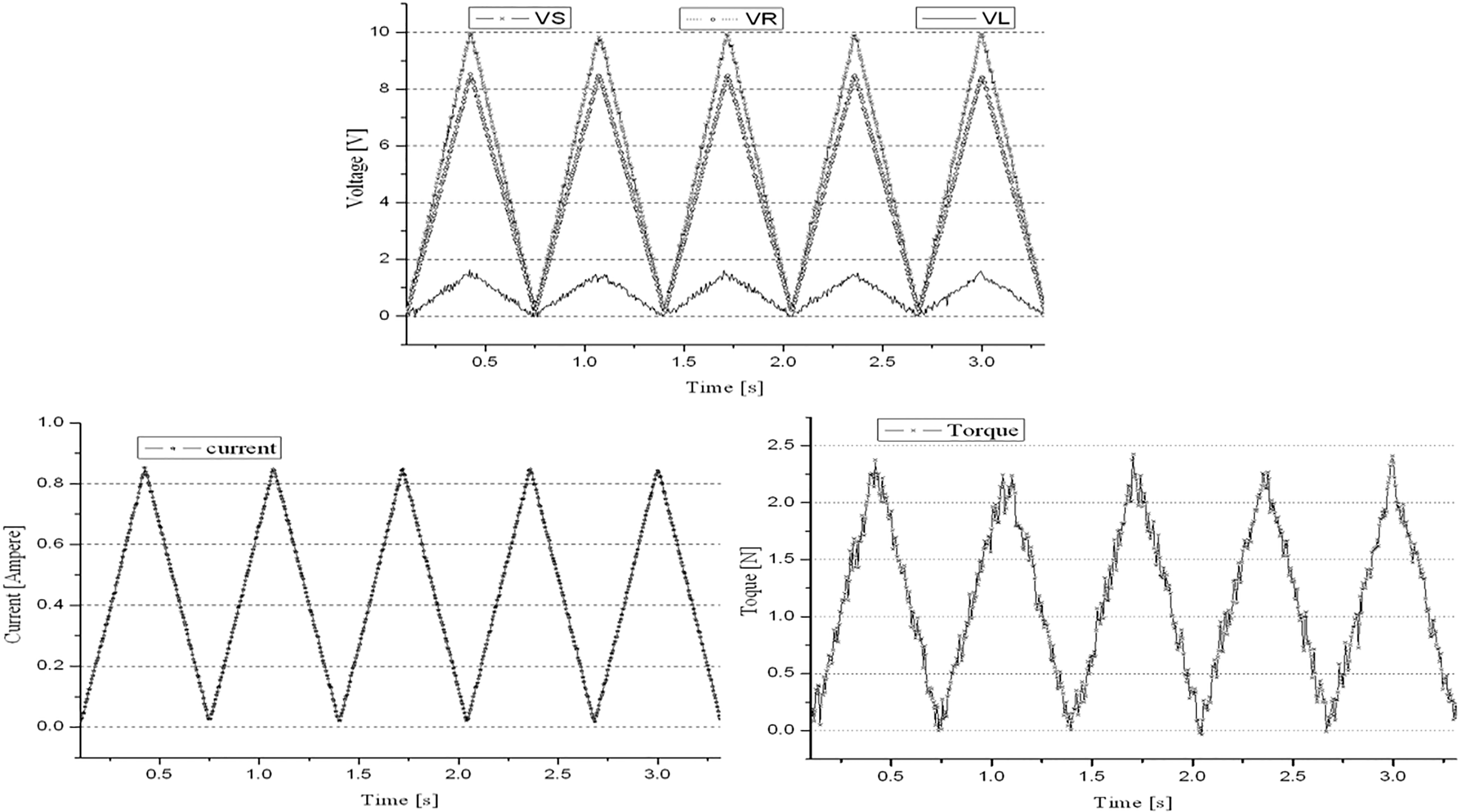
Measured hysteresis curve with a least square fitting curve for 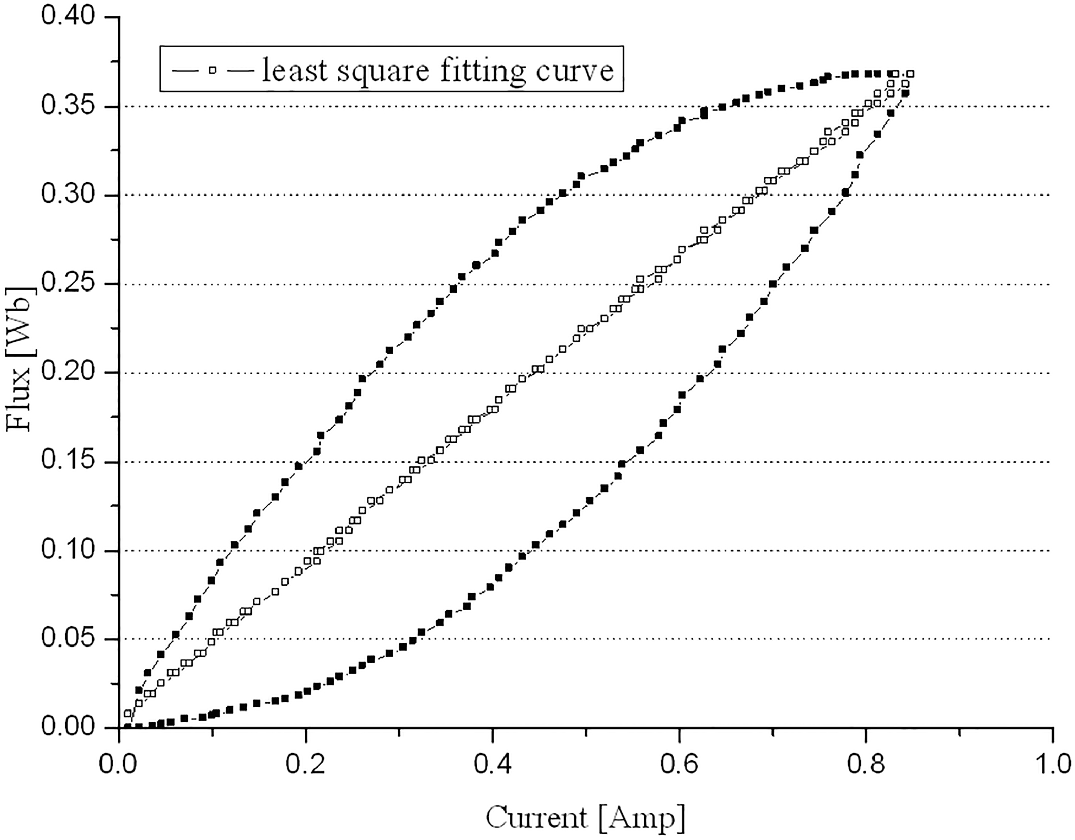
Torque versus flux.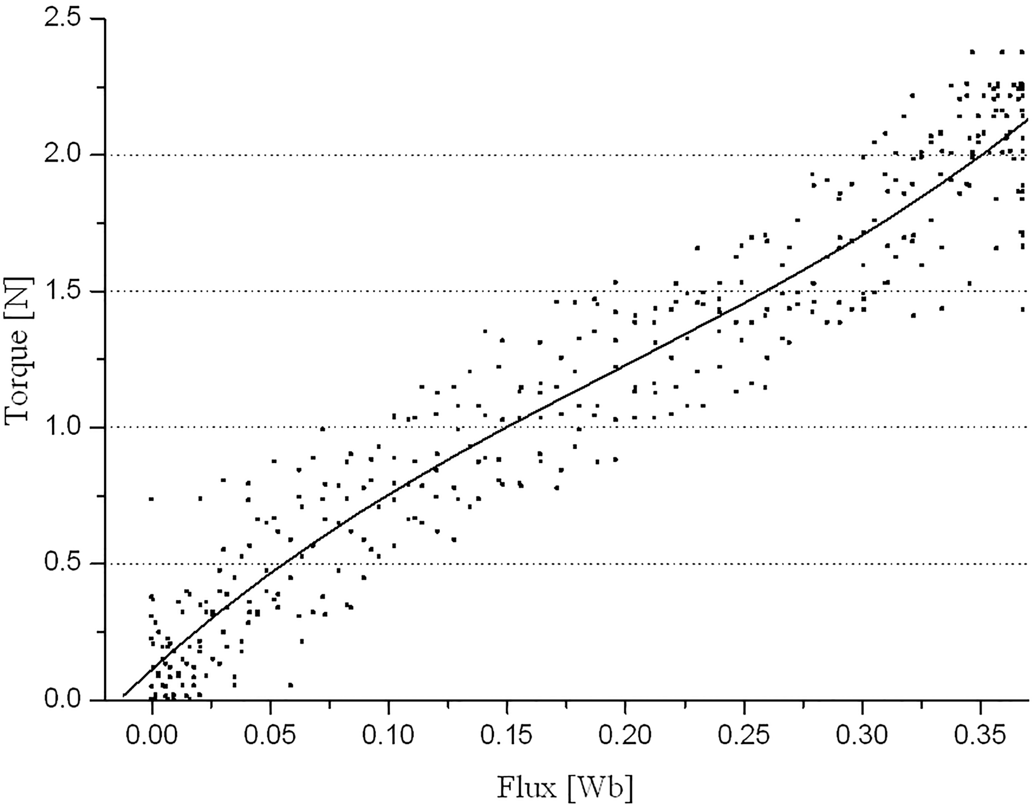
Calculated curve for 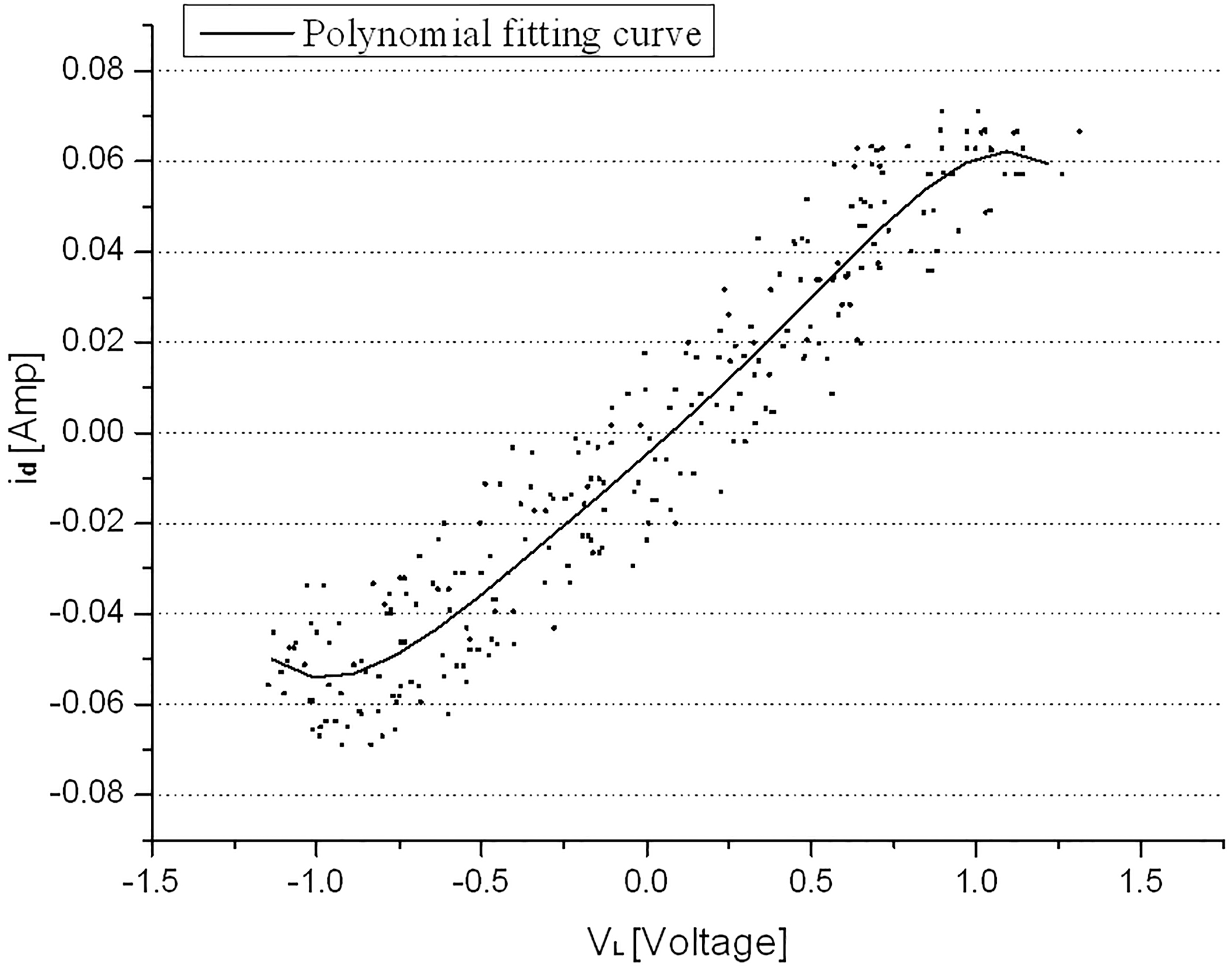
To verify the nonlinear model of MR brake, experimental setup is constructed as shown in Fig. 9. This setup is consisted of four main parts: a commercial MR brake, a torque transducer, a geared AC servo motor, a DC power supply. The shaft of MR brake is attached to a flexible coupling to ensure proper alignment. The other side of the coupling is connected to one shaft of torque transducer, which has a capacity of 5 Nm and is able to work a max. speed of 4000 rpm. The other side of the torque transducer is connected to AC servo motor. The servo motor is comprised of motor and inverter, which is designed for control of the motor direction and variable speed operation. A programmable DC power supply is used to provide the input voltage to the magnetic coil of the MR brake and can provide 0
The lists of experimental hardware used
The lists of experimental hardware used
Block diagram of the proposed nonlinear model of MR brake.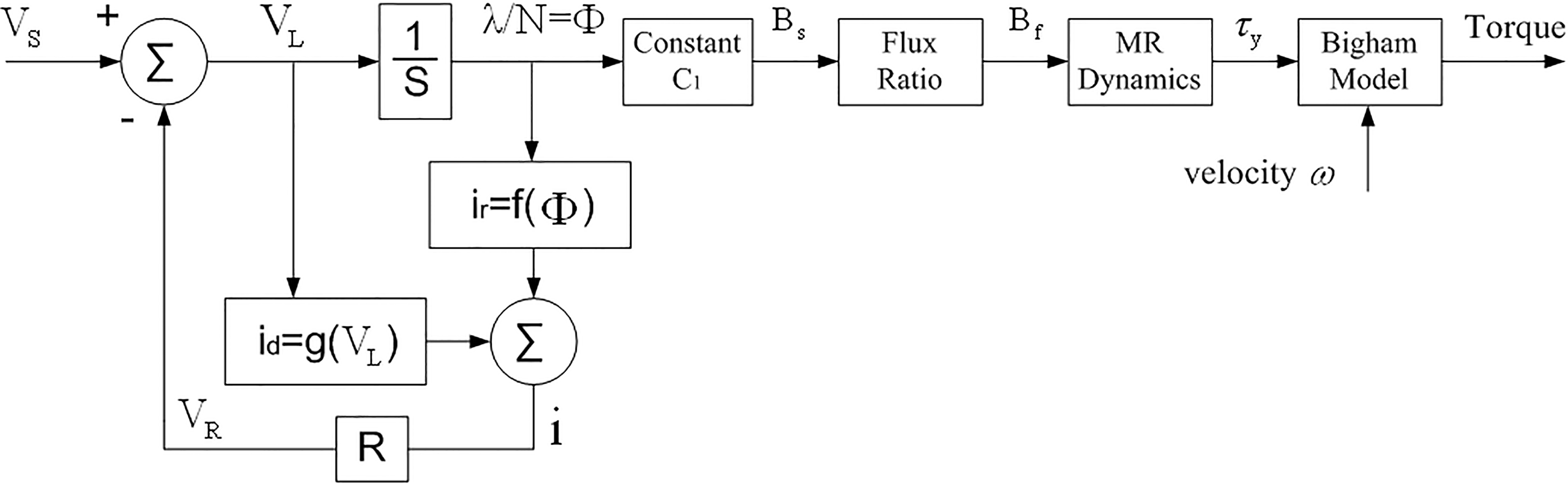
Experimental setup.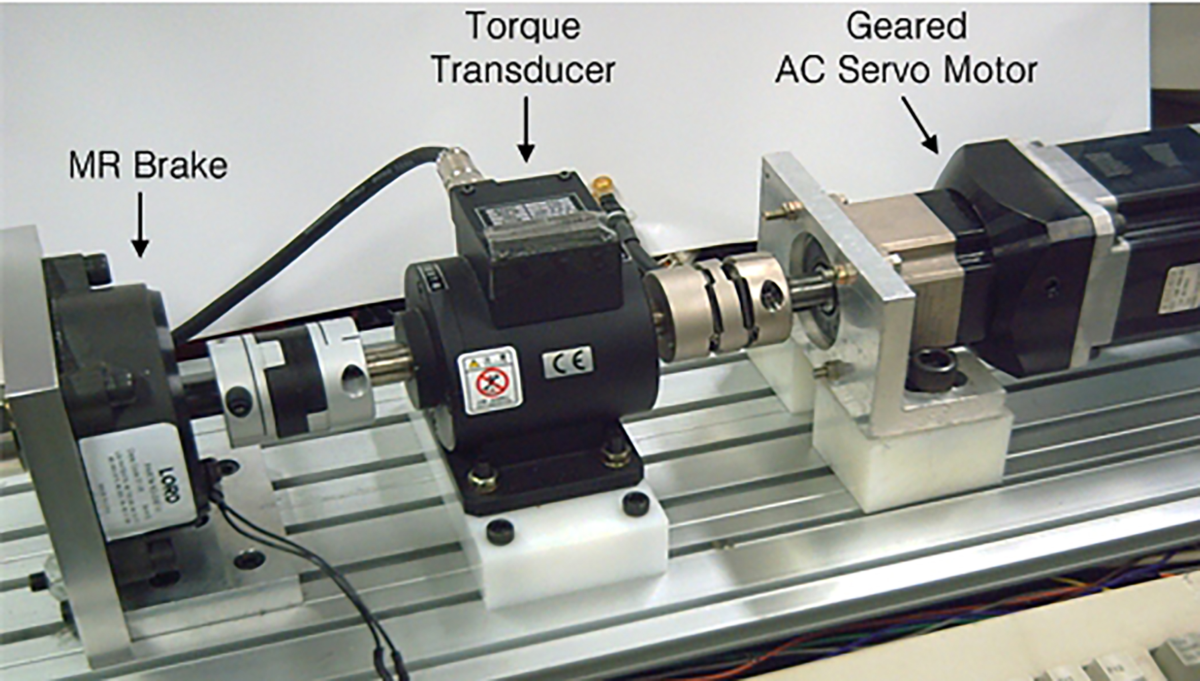
In this experimental setup, two parameters can be changed by the operator: the velocity of AC motor and the voltage applied to the MR brake. Figure 10 shows the characteristics with respect to the change of the input current (a) and rotational speed (b) of MR brake. Five typical rotary speeds, i.e., 200, 300, 400 and 500 rpm, were used at various ranges of 0.0 V, 2 V, 4 V, 6 V, 8 V and 10 V. As shown in Fig. 10a, it can be observed that the maximum resistant torque is around 2.4 Nm when the applied voltage is 10 V and the resist torque of MR brake is independent of rotational velocity and almost proportional to the input voltage, especially when the voltage is larger than 2 V. From Fig. 10b, when there is no current applied to the brake, the torque is around 0.24 Nm and due to the viscosity of MR fluid.
Obviously, the hysteresis behaviors of MR brake can be lead to undesired inaccuracies in any calculated torque. Prior to evaluation of the proposed nonlinear model of MR brake, hysteresis tests were carried out at a rotational velocity of 200 rpm, and the form of the offset sine wave input is
Characteristics of MR brake.
A sample set of experimental hysteresis data for different input excitation sources.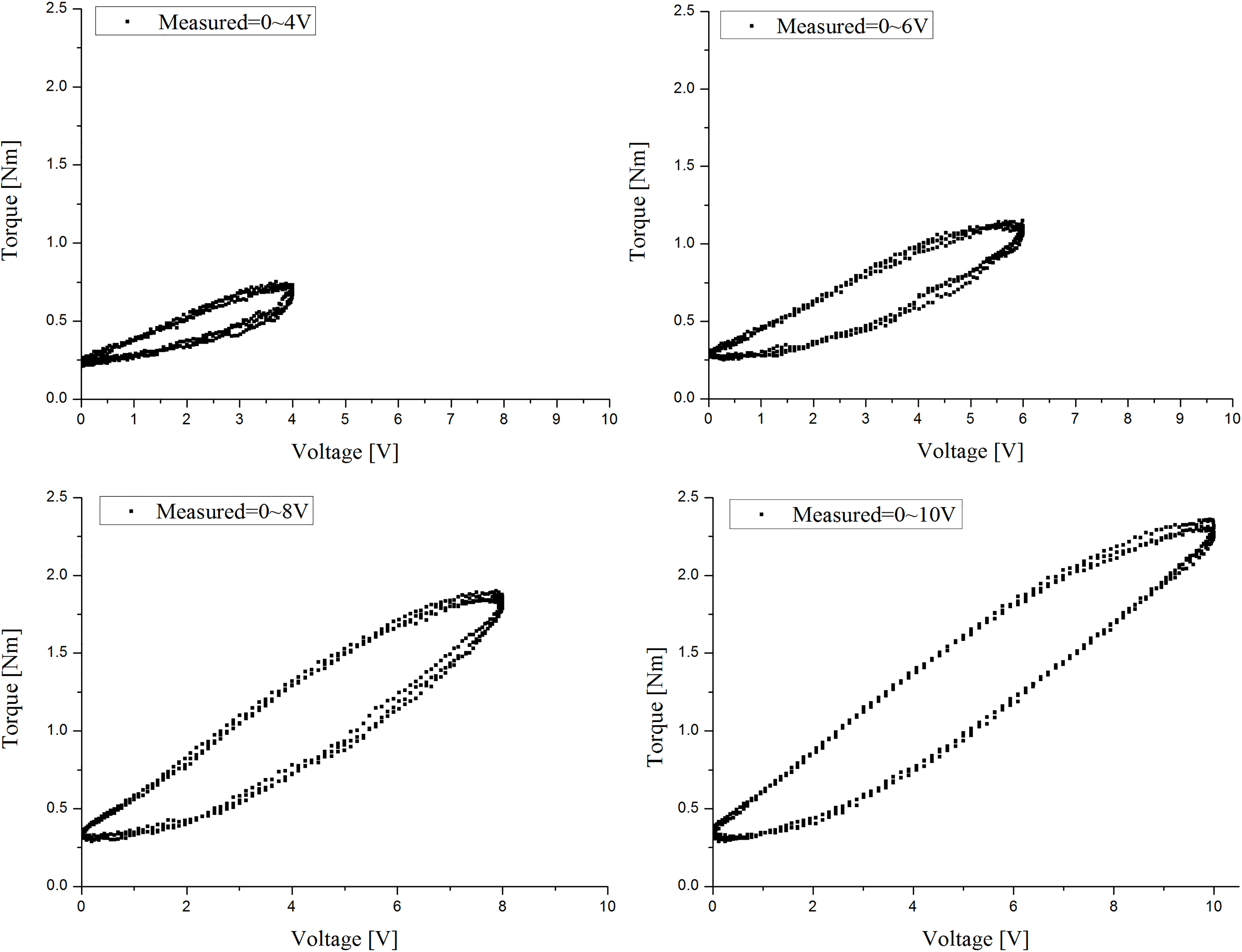
Comparison of the measured and the predicted data.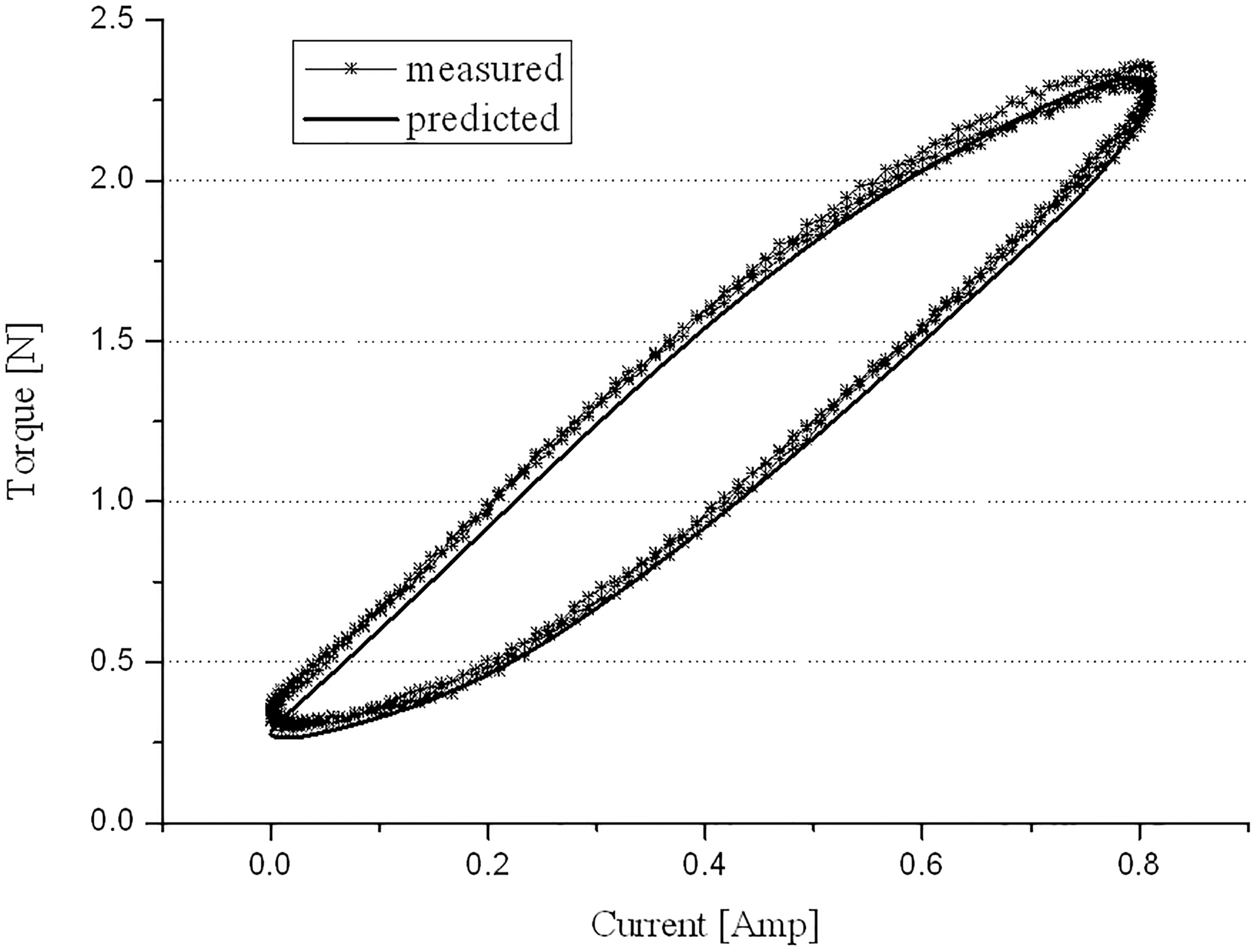
Frequency response of MR brake used.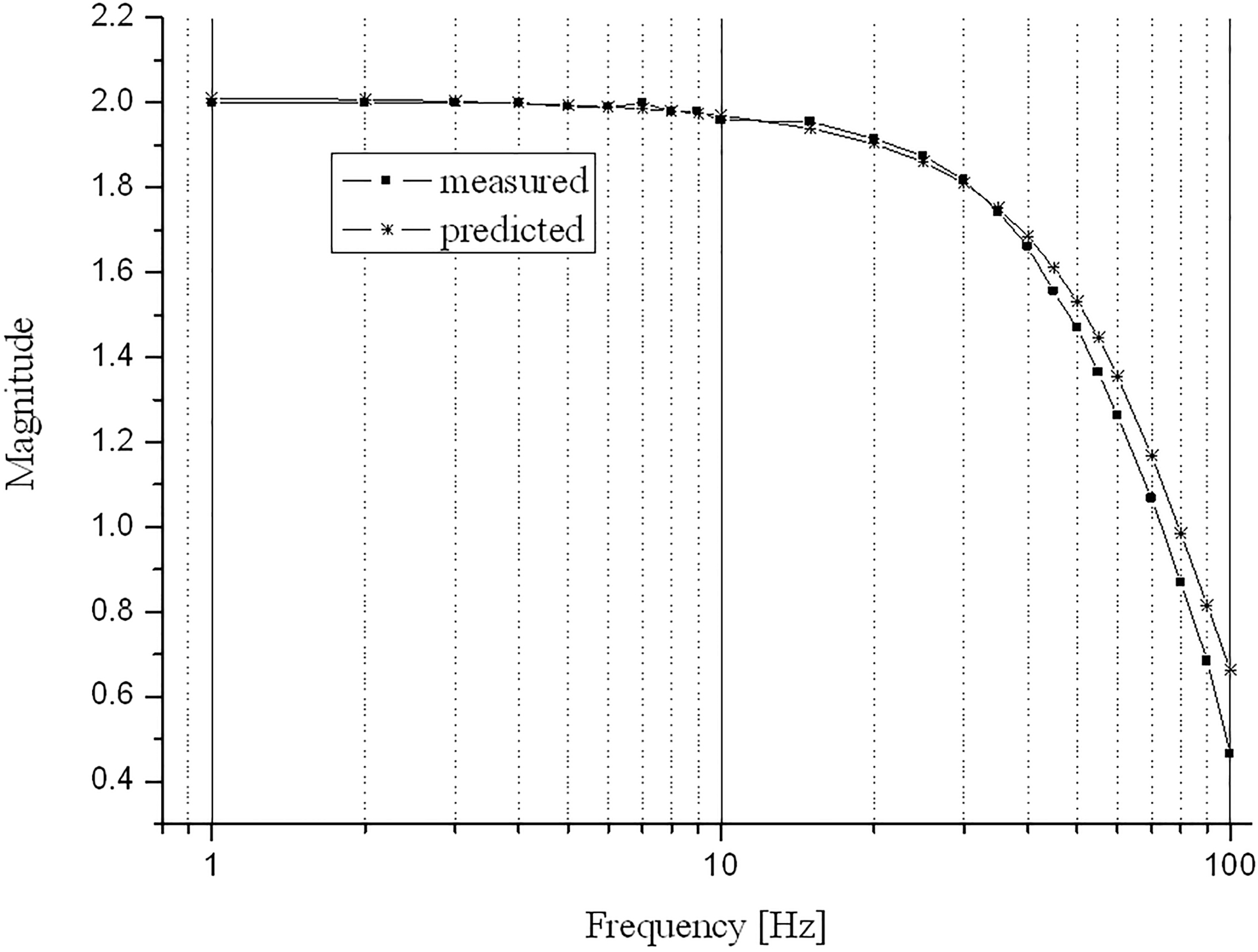
The input voltage,
It is clearly seen that hysteresis behaviors of MR brake is exposed under various conditions between the resist torques and excitation inputs. As clearly also observed from the results, the width of the hysteresis loop at lower excitation voltage is relatively narrowed, while at higher excitation voltage the width is revealed more significantly. This means that MR brake including hysteresis must be modeled through suitable hysteresis model for using a variety of applications such as precision positioning devices [21]. In order to show the performance of the proposed nonlinear hysteresis model of MR brake, a comparison between the predicted result and the corresponding measured result is investigated.
Simulation is conducted in Matlab/Simulink environment and then compared the corresponding measured result in Fig. 12. It is clearly seen that the proposed model predicts well the experimental hysteresis behavior of the MR brake. It is also worth meaning that the proposed model can be implemented to estimate the MR brake dynamics for the sake of a relationship between inputs and output torques. Although a description of the characteristics of frequency response was given by reference [21], the frequency test also has been conducted. The input part is rotated at a constant 200 rpm. A program written in C language generated an offset sine wave input according to Eq. (14) and collected the input voltage and torque data. The experimental result of the frequency response is shown in Fig. 13 with squares. As seen from Fig. 13, the predicted frequency response matches up to the experimental characteristics and MR brake used in this study has a bandwidth of nearly 35 Hz enough high to control.
A methodology to derive a nonlinear model of MR brake is presented to determine the torque versus input current relationship of MR brake. The proposed model is consisted of two models: a mechanical model based on Bingham model and a magnetic circuit model through a semi-empirical method. The semi-empirical method is proven successfully and estimated the nonlinear hysteresis behavior of MR brake. The first model using Bingham plastic model describes the magnetic field dependent fluid characteristics and the relation between the torque and the dynamic yield stress caused by the applied field. The magnetic circuit makes up the second model with the relation between the dynamic yield stress and the magnetic induction of MR fluid. Using the principal of continuity of magnetic flux, the magnetic induction of the material is determined. Due to the ferromagnetic property of the material used to form the flux path, MR brake is experienced hysteresis effect and thus its hysteresis behavior is approximated by third-order polynomial functions [19]. The final model of MR brake links both models together by the torque. A comparison between the predicted and the measured result is carried out by the form of an offset sine wav input at a rotational velocity. It is clearly that proposed model is reasonably predicted the hysteresis behaviors of MR brake. To evaluate the feasibility for a torque estimator in control use, the frequency response test of MR brake is carried out and shows that the predicted frequency response matches up to the experimental characteristics and MR brake used has a bandwidth of nearly 35 Hz enough high to control. Thus, the proposed nonlinear model of MR brake can be used as a torque estimator for practical torque control applications. Unfortunately, the behavior of MR brake is temperature sensitive. Since the tests described above are done for a particular operating temperature, future work will exist in implementing a temperature effects into the model.
Footnotes
Acknowledgments
This work was supported by International University of Korea’s research fund in 2017.