
Abstract
In this paper, a novel permanent magnet-assisted synchronous reluctance machine (PMASynRM) with rare-earth PMs and ferrite magnets is proposed. The performance of PMASynRM is discussed with respected to the different magnet ratio of rare-earth PMs and ferrite magnets. Some characteristics including the flux density, output torque, cogging torque, output power, power factor, torque ripple, loss, efficiency, and demagnetization are calculated by 2-D finite element analysis (FEA). The analysis results show that the excellent performance can be obtained by using hybrid magnet of rare-earth PMs and ferrite magnets with the suitable magnet ratio, and provide some desirable cost-performance trade-off.
Keywords
Introduction
Currently, permanent magnet electrical machines with rare-earth permanent magnets (PMs) exhibit excellent performances, such as power density, torque density, efficiency, power factor and a wide speed-regulation region [1, 2, 3, 4, 5]. However, there are some limits of the high cost and supply chain uncertainty for rare-earth PMs because of neodymium and dysprosium. Therefore, less or no rare-earth PMs in electrical machines can be considered to decrease the total cost of electrical machines. Although some electrical machines without rare-earth PMs can achieve some excellent performance including high power density, high torque density and high efficiency, such as switch reluctance machines (SRMs) [6] and synchronous reluctance machines (SynRMs) [7]. Nonetheless, there are some problems, such as the vibration and acoustic noise in SRMs [8, 9] and low power factor in SynRMs [10]. Moreover, rare-earth PMs can be partially replaced by low-cost ferrite magnets [11]. Although the performance of electrical machines with ferrite magnets can be improved, there are still some shortcomings, such as low power factor and low torque density due to low remanence of ferrite magnets.
In order to achieve high performance and reduce total cost of electrical machines, a novel permanent magnet-assisted synchronous reluctance machine (PMASynRM) with hybrid magnet of rare-earth PMs and ferrite magnets is proposed, of which the magnet ratio is an important factor of PMASynRM. In addition, the irreversible demagnetization of ferrite magnets should be considered when it operates in cold weather [12].
Therefore, the purpose of this paper is to investigate the performance of PMASynRM by using hybrid magnets with different magnet ratio. Some electromagnetic characteristics including flux density, output torque, cogging torque, output power, field-weakening capacity, power factor, torque ripple, loss and efficiency were calculated by 2-D finite element analysis (FEA). Meanwhile, the irreversible demagnetization behavior was examined in the worst condition of critical temperature (
Topology and parameters of PMASynRM
Machine topology
Figure 1a shows the stator of PMASynRM, of which the slot number is 48 and a distributed armature winding is applied. Figure 1b gives the 2D structure model of rotor, which mainly includes iron bridges, flux barriers, center ribs and rectangular PMs. The center ribs are designed trial and error to decrease flux leakage and achieve sufficient mechanical strength. The rectangular PMs are embed into rotor iron to produce radial magnetic field in PMASynRM. Some parameters including the shape and size of flux barriers, the width of iron bridges and center ribs, are optimized in [13]. Meanwhile, some characteristics with response to torque ripple, loss, efficiency, mechanical strength and irreversible demagnetization are discussed. Although the multi-layer of ferrite magnets was designed in the rotor of PMASynRM to increase the reluctance torque, the flux density is low because of the low remanence of ferrite magnets, and the power factor and torque density are not ideal. Therefore, the rotor topology with ferrite magnets and rare-earth PMs is proposed for improving the performance and reducing the cost of machine, as shown in Fig. 1c. Meanwhile, as shown in Fig. 1b, c and d, the shape and thickness of flux barriers are the same, and the equal sizes of iron bridges and center ribs are adopted, but the magnet ratios of three models are different.
Some parameters of PMASynRM
Some parameters of PMASynRM
Structure of PMASynRM with different PMs.
Some parameters are given in Table 1, which consists of pole number, outer diameter of stator, stack length, voltage in DC side, slot fill factor and winding resistance at 20
In order to simplify the analysis model, the magnet ratio of
where
where
Thickness of PMs.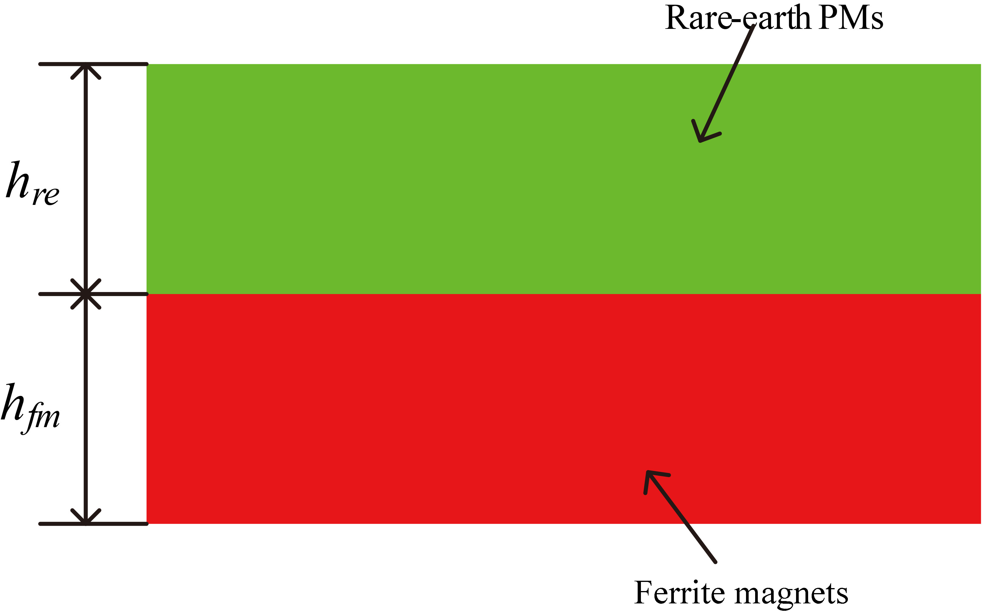
For the purpose of decreasing computation time under maintaining a higher precision, one-eighth model and odd symmetry boundary condition is adopted in PMASynRM. In this section, some performances are computed and analyzed comparatively, such as some electromagnetic characteristics including output power, output torque, cogging torque, torque ripple, power factor, rotor loss, stator loss and efficiency are calculated in constant region and field-weakening condition. The software of Maxwell is adopted in this paper.
Flux density
The flux density in the rotor and stator at no load is shown in Fig. 3. It can be found that flux density increased with the increasing of magnet ratio. In addition, The flux density in center ribs and iron bridges are saturated because of flux leakage. Although rare-earth PMs can provide more magnetic energy to achieve the higher torque density, it also causes magnetic field saturated and the increasing of iron loss. Furthermore, the magnet ratio should be designed to improve the utilization rate of rare-earth PMs in consideration of its higher price.
Flux density of rotor and stator at no load.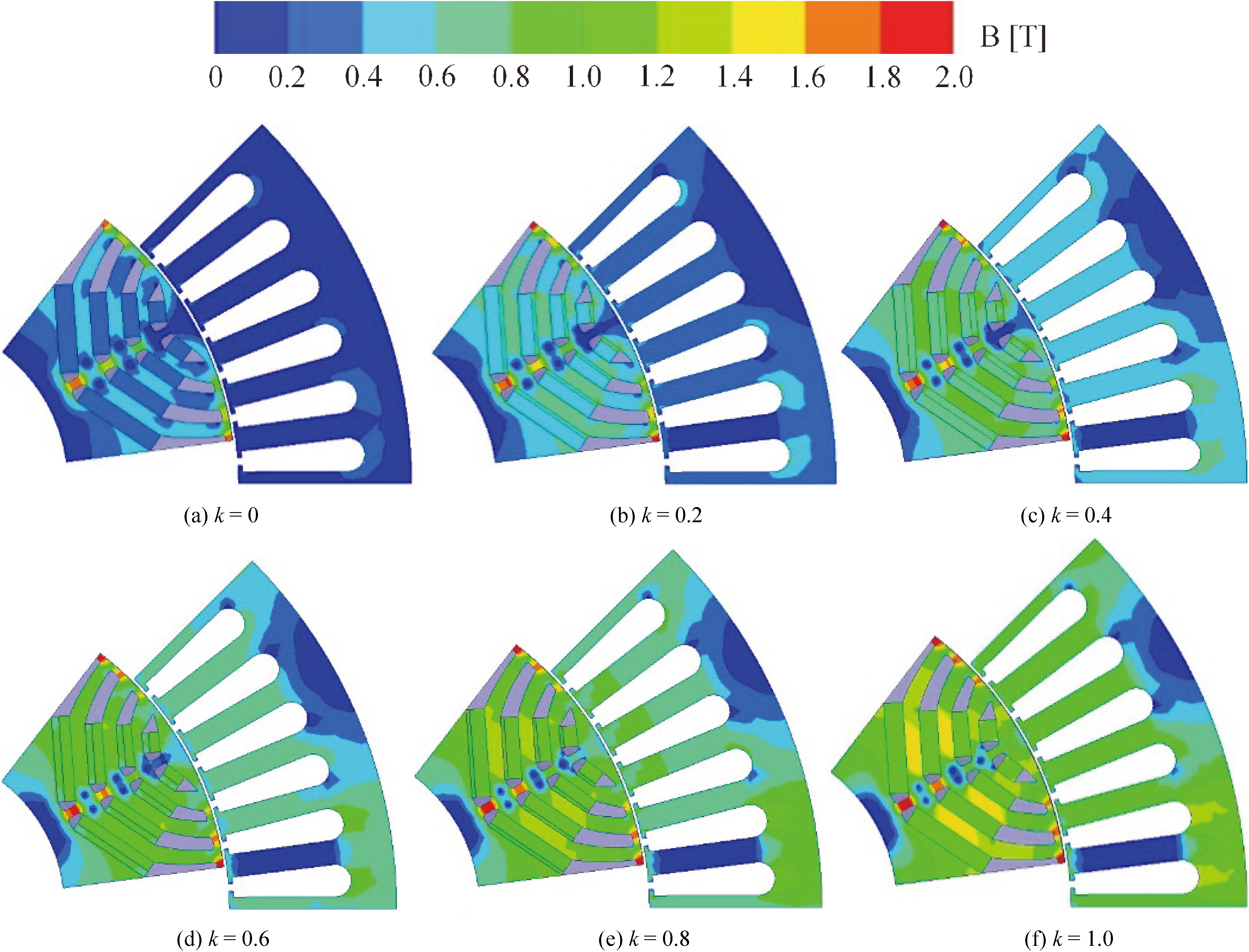
The output torque versus current phase angle is given in Fig. 4a, which shows that there is a great effect on output torque due to the magnet ratio.
Electromagnetic characteristics.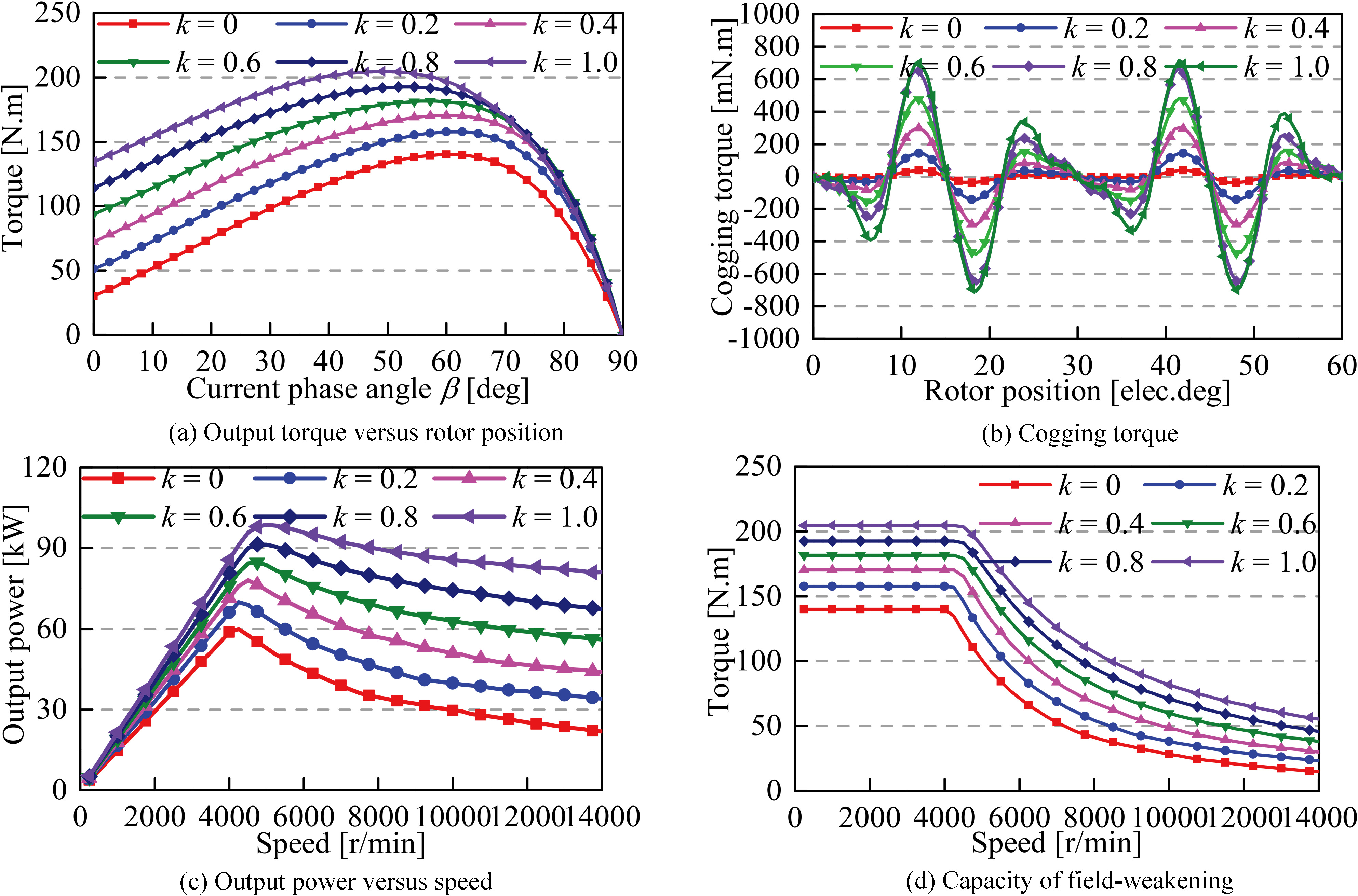
The cogging torque versus rotor position is shown in Fig. 4b. The periods of cogging torque in one electrical cycle can be calculated by the following equation.
where
As shown in Fig. 4b, it has 12 periods of cogging torque in one electrical cycle decided by 8 poles and 48 slots of PMASynRM. The amplitude of cogging torque is the largest by adopting rare-earth PMs, and smallest with ferrite magnets. It is determined by the different coercive force and remanence of rare-earth PMs and ferrite magnets, which leads to the different magnet strength and permeance variation of the hybrid magnets in the magnetic circuit. However, the curves of cogging torque are similar, which due to the same rotor and stator structure of PMASynRM.
The output power with different magnet ratio is given in Fig. 4c. The maximum output power is about 98.7 kW when
The map of power factor are given in Fig. 5. It can be found that high power factor can be obtained by adding some rare-earth PMs in rotor. Moreover, the area of power factor that higher than 0.600 is increased with magnet ratio, which due to much rare-earth PMs with high coercive force and larger remanence are applied in rotor. Therefore, it indicates that the power factor in all the operate area can be improved with an appropriate magnet ratio.
Power factor.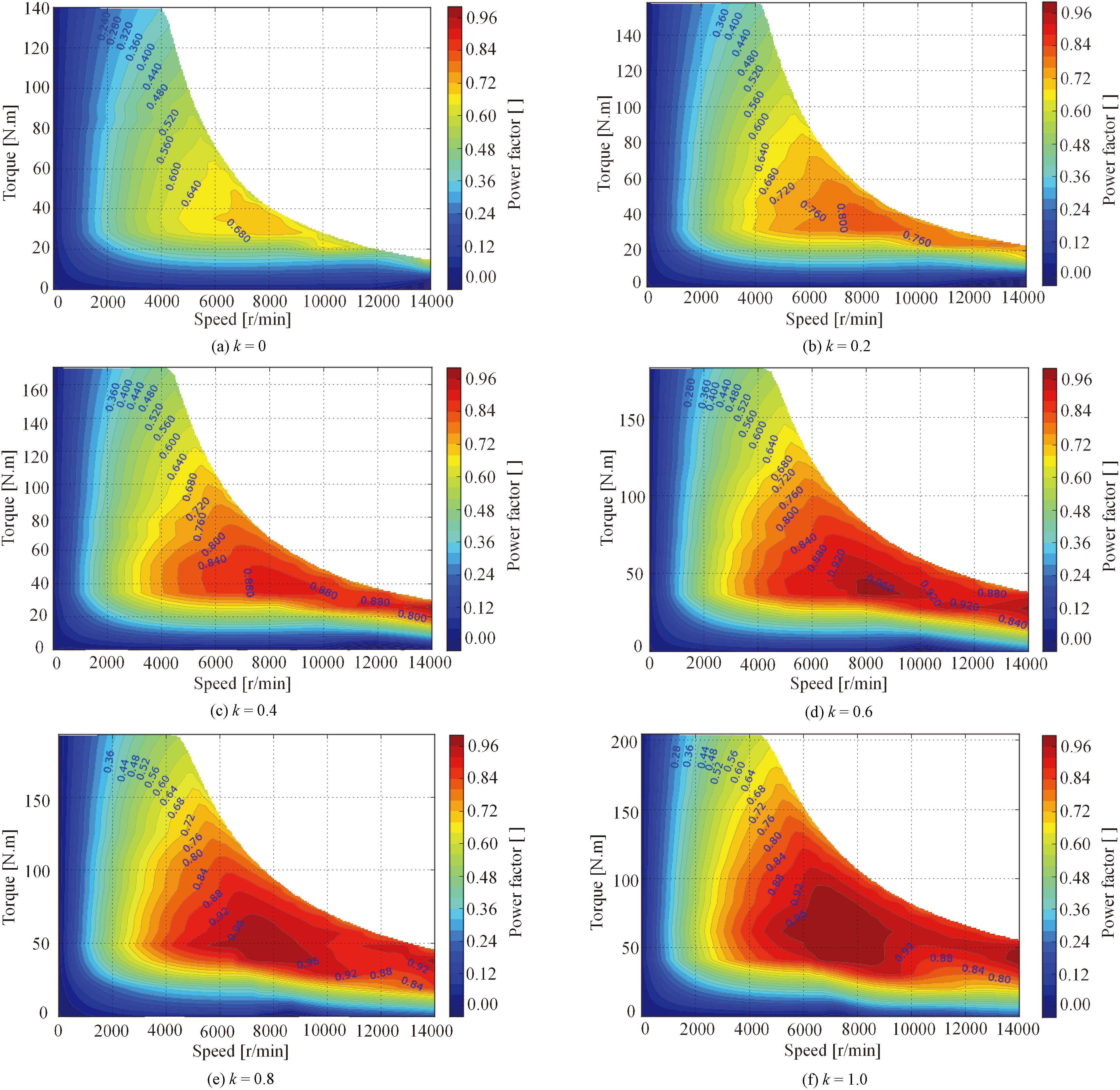
The average electromagnetic torque and torque ripple are computed by 2D FEA, and the torque ripple can be defined as
where
Although the torque ripple characteristics are investigated in the literature [14, 15], there is a limit of computing the torque ripple at a fixed operational condition, such as rated load or the maximum load. In order to obtain a comprehensive comparison for PMASynRM with different magnet ratio, the torque ripple maps in all operational region are given in Fig. 6. It shows that the maximum torque ripple is 13.8%, 9.3%, 10.5%, 9.0, 13.8 and 22.3% when
Torque ripple maps.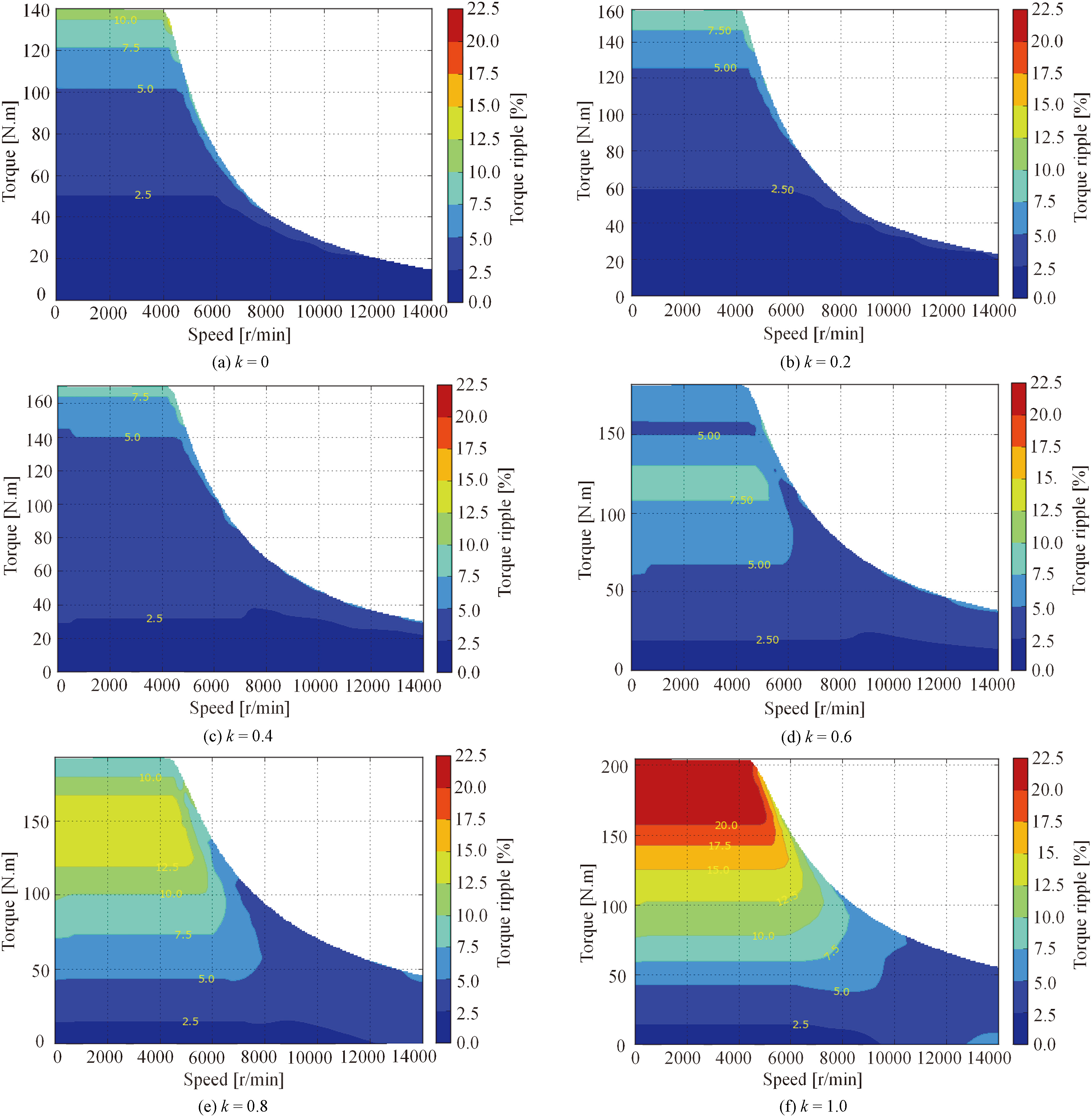
The loss and efficiency are the significant parameters in motors. The iron loss, copper loss and efficiency can be calculated by the following equations.
where
Iron loss.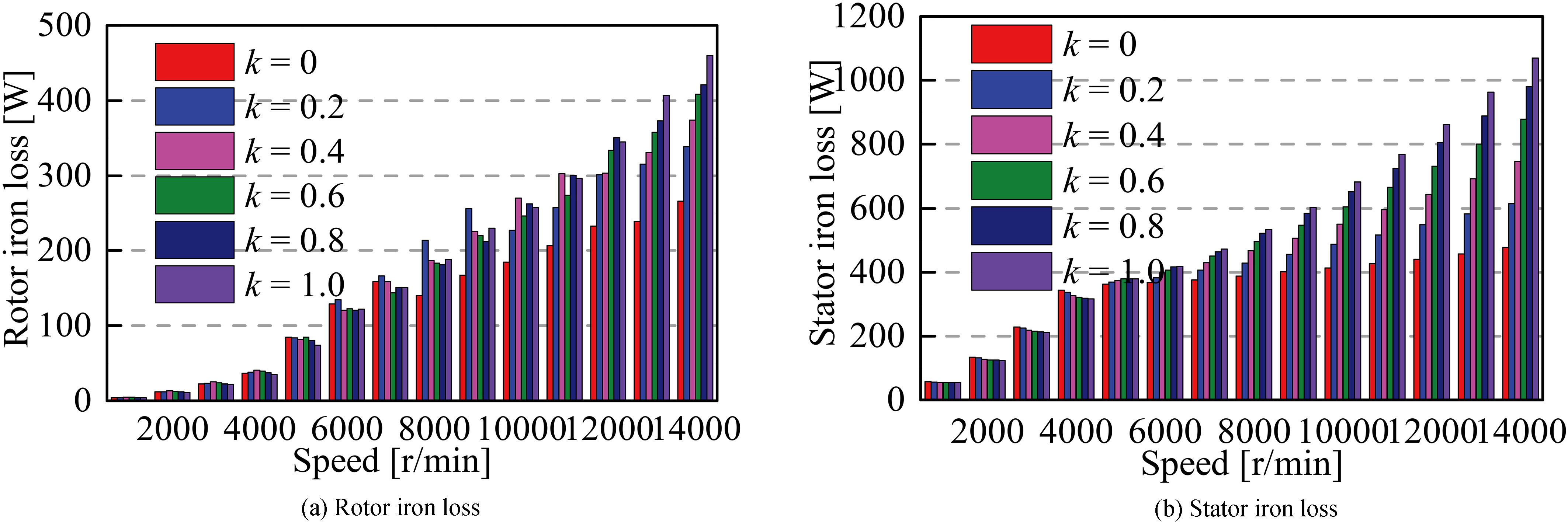
Despite of the different magnet ratio when estimating of loss and efficiency, copper loss does not changed with magnet ratio since the same control strategy (MTPA) is adopted. Therefore, iron loss is the most important factor for evaluating the total loss and efficiency. The iron loss in PMASynRM with different magnet ratio is given in Fig. 7, which shows that the stator iron loss accounts for a large proportion of the total iron loss. Rotor iron loss increased with speed, as shown in Fig. 7a. Furthermore, rotor iron loss increased with magnet ratio when the machine speed above 12000 r/min, which due to larger magnet ratio resulting saturation in rotor. Stator iron loss is given in Fig. 7b, and it can be found that stator iron loss increased with speed. In addition, stator iron loss increased with magnet ratio when operating at speed above 6000 r/min. However, stator iron loss is almost unchanged with magnet ratio when operating at speed under 5000 r/min.
Efficiency maps.
The efficiency map of PMASynRM with different magnet ratio is shown in Fig. 8, where MTPA control strategy is adopted. It should be noted that the eddy current losses in the armature windings and PM eddy loss are not considered when computing the efficiency of PMASynRM. The mechanical frication losses is set to 50 W, which references to mechanical frication losses at 3000 r/min. The copper loss is calculated by 2-D FEA at 20
The above characteristics demonstrated that the high efficiency can be achieved in PMASynRM by using rare-earth PMs and ferrite magnets with different magnet ratio.
The capability of withstand demagnetization is crucial to PM machines for the safe operation. In order to estimate the worst condition, the irreversible demagnetization is calculated in PMASynRM. Although the rare-earth PMs will be demagnetized at high temperature, the temperature of machine may be lower than the highest working temperature of rare-earth PMs by using some cooling methods. Hence, the demagnetization of rare-earth PMs can be neglected in this paper. Owing to the performance of ferrite magnets are effected in cold weather, which results in a deterioration of machine performance. Consequently, the demagnetization of ferrite magnets of Y30BH should be investigated, and the lowest temperature is set to
Demagnetization curve of ferrite magnet (Y30BH).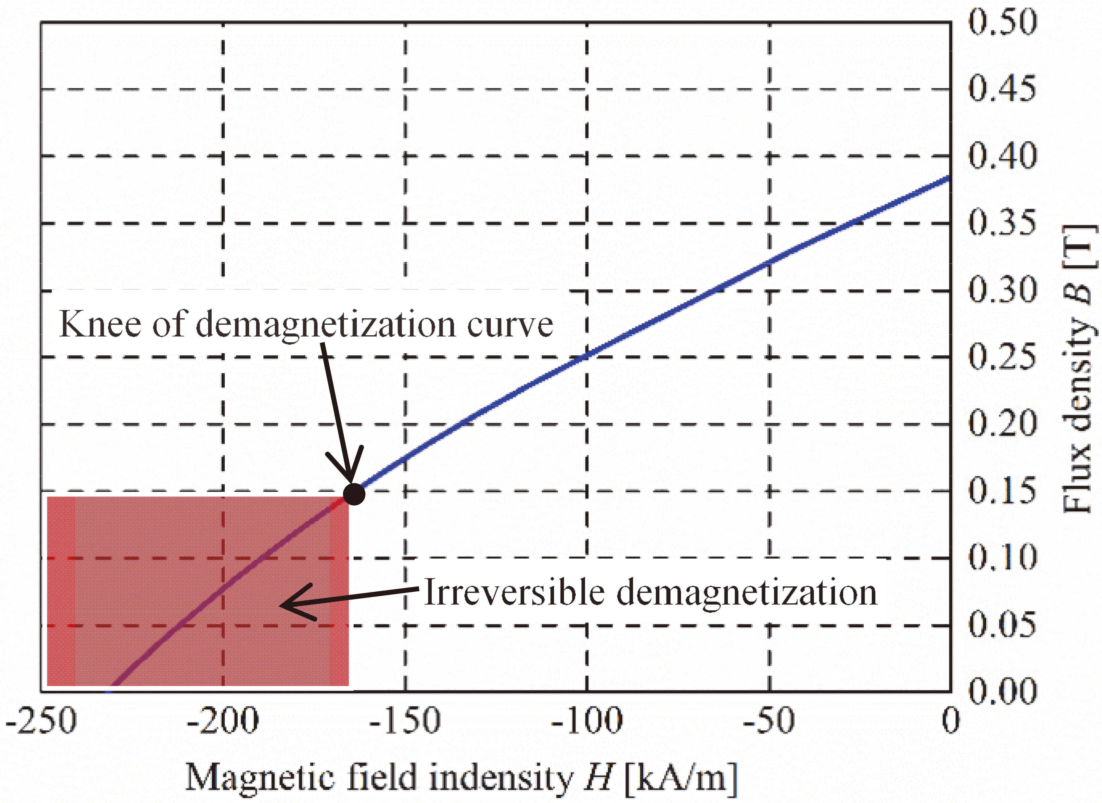
Contour plots of flux density at 500 A.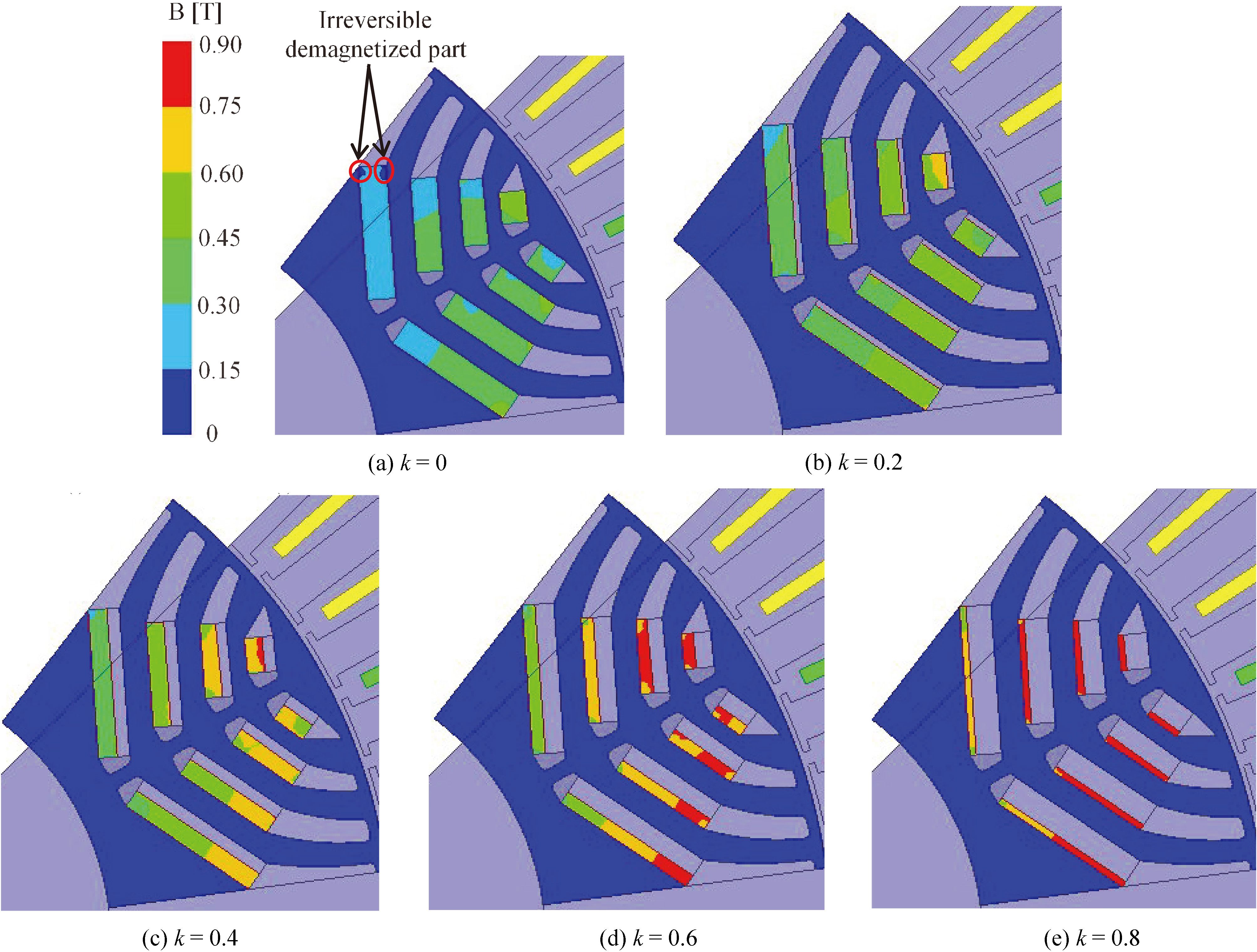
The demagnetization curve of ferrite magnet (Y30BH) used in the proposed PMASynRM is shown in Fig. 9. The irreversible demagnetization will be occurred when the flux density of Y30BH is lower than the critical flux density at the knee of demagnetization curve. The knee of irreversible demagnetization is about 0.15 T (with margin) at
Figure 10 shows the contour plots of flux density at 500 A. It shows that the ferrite magnets of the fourth-layer is partial irreversibly demagnetized, as shown in Fig. 10a. Due to the MMF from the stator winding, the flux flows primarily through the center ribs and iron bridges. However, the flux also flows through the flux barriers because the thickness of flux barriers is smaller than that of ferrite magnets. So the flux density is too low in side part of ferrite magnets, and the irreversible demagnetization is occurred. However, the irreversible demagnetization rate is only about 5.3%, and the irreversible demagnetization is not occurred when k is 0.2, 0.4, 0.6 and 0.8 due to the increase of MMF by adopting rare-earth PMs, as shown in Fig. 10b, c, d and e, respectively. The magnet flux in ferrite magnets become large with the increase of magnet ratio due to the more rare-earth PMs are applied, as shown in Fig. 10b, c, d and e.
Some parameters with different magnet ratio
Some parameters including torque density, power density, PM material costs and the maximum efficiency are compared for PMASynRM with different magnet ratio, as shown in Table 2. It should be worth mentioning that all PMASynRMs have the same structure and excitations, and the only difference is magnet ratio. The proposed PMASynRM with rare-earth PMs has the highest torque density, power density and total cost, which is 1.46, 1.65, and 301 times of ferrite magnets, respectively. It indicated that potentially offer some desirable cost-performance trade-off. Therefore, if there is no limit to the machine volume, the total cost of PMASynRM can be reduced for obtaining the same output torque by using low-cost ferrite magnets. In addition, the high torque density can be obtained in the proposed PMASynRM when the multi-layer structure of rotor is adopted by using hybrid magnets. The proposed PMASynRM can be applied in aerospace, vehicle traction, industrial application, and energy power generation.
Conclusion
A novel rotor structure of PMASynRM with different magnet ratio is presented in this paper. Some electromagnetic characteristics including output torque, cogging torque, output power, power factor, torque ripple, loss and efficiency are obtained by FEA. Moreover, the irreversible demagnetization are investigated in the worst condition at critical temperature of
As for future work, the hybrid magnet with parallel-excited will be investigated in PMASynRM, and compare with serial-excited of hybrid magnet, in order to improve the torque density, power factor and efficiency.
Footnotes
Acknowledgments
This work is supported by National Natural Science Foundation of P.R. China (No. 51267006), Plan Project of Jiangxi Province of P.R. China (GJJ12332, 20122BAB206031, 21767009, GJJ160598, 20151BBE50109 and 20153BCB23012), Program of Qingjiang Excellent Young Talents, JXUST.