
Abstract
The magnetic flux density in the magnetizing coil during the hysteresis measurement was calculated. The influence of a slot, machined in a ferromagnetic plate was simulated. The size of the magnetizing yoke was changed and the influence of this modification was studied on the detectable flux density. The size of the slot and the thickness of the air gap, which appears between the magnetizing yoke and plate’s surface, was also taken into account. It was found that by this simulation the experimental conditions could be successfully modelled. A sensitivity analysis of the studied nondestructive testing setup was also performed and the impact of different experimental parameters was analyzed. The results of simulation can be used successfully for determining the optimal parameters of the actual measurement arrangement if method Magnetic Adaptive Testing measuring technique (which is based on systematic measurement and evaluation of minor magnetic hysteresis loops) is applied.
Keywords
Introduction
For pipes used in industry, e.g. in chemical and power plants, wall thinning is one of the most serious defects [1, 2]. Detection and evaluation of the thickness reduction of pipes are very important issues for prediction of lifetime of the pipes in order to avoid severe accidents. Local wall thinning on the inner surface of a pipe (e.g. in a nuclear power plant) may occur due to the stream of coolant flowing inside the pipe, causing a serious problem of maintenance of the piping systems. The inspection should be done from the outer side of the pipe. There is a special concern on the local wall thinning at locations under an enforcement shield that covers outside of the pipe, where a branch pipe is connected to the main one. Because the enforcement shield and the pipe wall form two layers of metal, it is difficult to inspect inside of the pipe under the enforcement shield by any ultrasonic method. Magnetic methods seem to be effective electromagnetic nondestructive testing techniques for inspection of local wall thinning at locations under an enforcement shield. As an example, the feasibility of magnetic flux leakage (MFL) method for estimation of wall thinning of pipes under reinforcing plates in nuclear power plants was discussed. Assessment of size of a slit fabricated on the undermost layer of the layered specimen was shown to be possible from the flux leakage profile. It was shown that conditions of wall thinning under reinforcing plates can be monitored by MFL method [3, 4]. Perhaps the most promising way for detection of local wall thinning in ferromagnetic plates is a recently developed nondestructive method, called Magnetic Adaptive Testing (MAT), which is based on systematic measurement and evaluation of minor magnetic hysteresis loops [5]. It was shown that even a relatively small, local modification of the plate thickness could be detected with adequate signal/noise ratio from the other side of the specimen. The measurements gave proper results also, if the investigated plate was covered by other plate(s) [6, 7].
To improve the applicability of MAT, the measurement conditions should be optimized. It is important to study, how the modification of the measured hysteresis loops, caused by the presence of an artificial slot in the investigated ferromagnetic plate(s) are influenced by the geometry of the applied magnetizing yoke, by the height of the air gaps between the magnetizing yoke and sample surface (and also between the plates) and also by the size of the slot. For this purpose numerical simulation was performed.
The numerical simulation of the change of magnetic flux density caused by the presence of an artificial slot, placed on the opposite side of the plate to be magnetized in a system contaning several plates has never been simulated previously- to our best knowledge. In several works [8, 9] it was simulated how different flaw geometries and sizes influence the measured signal, but these calculations were made for the case of a surface flow.
In our recent work we calculated how the geometrical parameters of the measured arrangement affect the change of the magnetic flux inside the magnetizing coil, which is the main source of the detected change in the measured signal. The yoke size and influence of air gap (which is extremely important in open magnetic circuits) were also taken into account in a three plate system of ferromagnetic plates.The result of simulation will help to find the optimal parameters of the experimental arrangement.
The magnetizing yoke over the system of three iron plates, the undermost containing the slot.
A system of three ferromagnetic plates was investigated. The size of the investigated iron plates was 180
The geometry of the magnetizing yoke.
Calculations were performed for single, double and triple sheet system (This latter configuration is sketched in Fig. 1). The magnetic flux was calculated by systematic modification of the size of the magnetizing yoke (the distance between yoke legs was modified) for the three different slot widths. The influence of air gap was also taken into account, between the yoke and surface, and also between the plates. Air gaps are indicated by blue color in Fig. 3.
The air gaps between adjacent metal surfaces.
The AC/DC Module of the Comsol Multiphysics
Here
Worth noting, that the air gap can be modeled in the software as a specific surface called “thin low permeability gap”. This efficient modeling method makes the volumetric discretization of the air gap unnecessary. The gap is represented during the simulation by the following interface condition:
where
The variation of magnetic flux,
The relative change of magnetic flux as a function of the yoke legs distance and the air gap, for the three investigated configurations.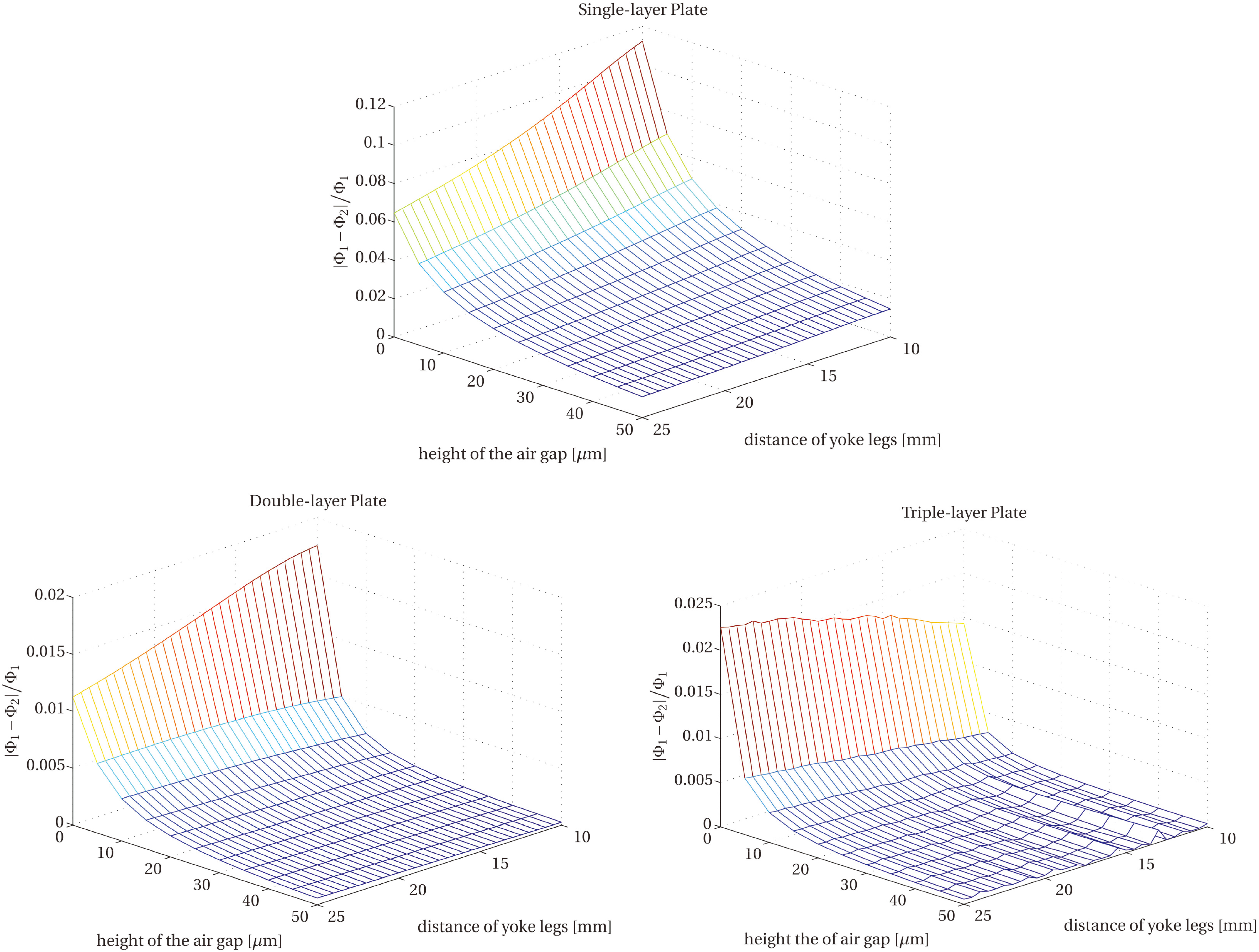
Figure 4 shows for the single, double and triple layer configurations, which contain 10 mm wide and 2 mm deep slot, how the relative change of the flux,
Changing of the magnetic flux in the single layer configuration due to the presence of 5, 10 and 15 mm wide slots as a function of the distance between yoke legs. a) no air gap , b) 5 
By taking into account the results of simulation, in the following figures we show, how the change of the magnetic flux – due to the presence of the slot placed in the bottom layer – depends on the distance between the legs of the magnetizing yoke, as sketched in Fig. 2. The flux change in the vertical axis means the ratio of the magnetic fluxes computed without and with the slot, respectively. Three different widths of the 2 mm deep slots (5, 10 and 15 mm) were considered in each case. Figure 5 shows the results obtained for the single layer (single plate) configuration, while Figs 6 and 7 do the same for the double and triple layer configurations. The calculations were performed for three different thicknesses of the air gap (0, 5 and 10
Changing of the magnetic flux in the double layer configuration due to the presence of 5, 10 and 15 mm wide slots as a function of the distance between yoke legs. a) no air gap , b) 5 
Changing of the magnetic flux in the triple layer configuration due to the presence of 5, 10 and 15 mm wide slots as a function of the distance between yoke legs. a) no air gap , b) 5 
Calculations were performed also for those cases, where air gaps were supposed not only between the magnetizing yoke and plate’s surface but also between the adjacent plates. As an illustration of these simulations, Fig. 8 shows the changing of the magnetic flux in the triple layer configuration due to the existence of 5, 10 and 15 mm wide slots as a function of the distance between yoke legs if 5
Changing of the magnetic flux in the triple layer configuration due to the presence of 5, 10 and 15 mm wide slots as a function of the distance between yoke legs. 5 
The influence of the air gap itself was also evaluated from the simulated results. For instance, Fig. 9 shows how the maximum of the relative flux changing (peak values of the curves in Figs 5, 6 and 7) depends on the thickness of the air gap in the single layer configuration with a 10 mm wide slot. The curves are given for different yoke sizes. Similar functions were obtained for the double and triple layer configurations, but not presented here.
The maximum flux ratio as a function of the air gap for different yoke sizes.
It is obvious from Figs 4 and 9 that the air gap, which is inevitable in all such types of experiments, has the most significant influence on the magnetic flux, while other parameters (such as the distance between yoke legs) have much weaker effect. Evidently, the examiner tries to keep the air gap as small as possible during the measurement to avoid this unwanted effect, provided he/she can get control on it. At least, it is important to keep the air gap constant in order to perform reliable and reproducible measurements.
The simulation also revealed that the flux change remains well measurable even for a relative large air gap (like 20 or 25
The maximum relative flux change as a function of distance between yoke legs for two thicknesses of air gap between the yoke and plate, in the single plate configuration with a 10 mm wide slot.
Unlike the air gap, other parameters, e.g. the size of the yoke, are more-or-less the examiner’s choice. Simulations can help to optimize the measurement configuration to get as high sensitivity in the local wall thinning inspection as possible. For example, the flux change caused by plate thinning (slot) has a definite local maximum as function of the yoke size. This means one can optimize the size of the yoke for detecting the presence of the slot. Obviously, the optimal distance of yoke legs is smaller than slot width in a single layer configuration, while it becomes larger in the double and triple layer configurations. Therefore in the practical application, where the defect size is usually not known in advance, choosing a larger magnetizing yoke might yield better results. Moreover, the change in the magnetic flux due to the slot does not seem to be very sensitive to the choice of the yoke’s size (10% or less), which underlines the reliability of the measurement.
The maximum value of relative flux change as a function of the width of a 2 mm deep slot (single layer configuration, no air gap).
Finally, it was found that the flux change is roughly proportional with the size of the slot. An illustration to this is Fig. 11, in which the maximum relative flux change (as determined from Fig. 5a) is plotted as function of the slot width (single layer configuration, no air gap, slot depth is 2 mm). Notably this correlation, which agrees with our expectations, gives rise to methods for estimating the size of the defect from the measured signal.
In this section a sensitivity analysis of the above described nondestructive testing setup is presented, relying on the numerical simulation of the configuration. The original configuration is equipped here with further variable parameters, such as the thickness and permeability of the plates and the permeability of the yoke. All of this in order to examine the sensitivity of the measured signal with respect to them. Also the position of the yoke can be changed, which enables the latter scanning above the slot: the yoke can move along the top of the uppermost plate, in the direction perpendicular to the slot. The position of the yoke is equal to the distance between the center line of the slot and the yoke.
Let
The numerous methods can be divided into two main groups, such as local methods that aim at describing the effect of the parameters only around a mean value (e.g. perturbation method), and global methods that are based on the partitioning of the total output variance among the groups of the input variables according to their contribution to the total variance. In this work the Sobol-index technique is used, which belongs to the latter group. The technique is briefly summarized here for completeness.
Sobol-indices
The idea behind the Sobol-indices is to decompose the model function into the sum of orthogonal basis functions of increasing dimension, as an infinite expansion. Without the loss of generality it is assumed that all input variables are uniformly distributed in the
where
This expansion is shown to exist and to be unique [13]. The basis functions can be calculated in a recursive manner as follows:
where
where
and
The Sobol-indices are defined as:
that represents the contribution of a group of input variables to the total output variance. In the case of the so-called first order Sobol-indices, the groups consist of only one input variable. The sum of all Sobol-indices is 1, hence the value of an index can easily be interpreted as the importance of each variable or group of variables.
The number of model evaluations needed to be performed to a proper sensitivity analysis could be extremely high by increasing dimension, which results in a high cost in terms of computational time. Surrogate models such as Polynomial Chaos Expansion (PCE) provide the user a functional approximation of the model as a substitution that significantly reduces the cost of evaluation.
Let
with
The univarite functions are chosen with respect to the type of distribution, e.g. in the case of uniform distribution
In the practice the multi-indices need to be truncated to a finite set
Beyond reducing the computational cost of the model evaluation as a surrogate model, the main importance of PCE reveals in the computation of the Sobol-indices. Since both Sobol decomposition and PCE creates an expansion of the model and this expansion is unique, there is a strong connection between the two. Thus the Sobol-indices can be calculated from the coefficients of PCE as described in [14, 15].
The sensitivity analysis is performed with the consideration of the parameters shown in Table 1. It is assumed that all of them have uniform distribution in the given interval.
Input variables and their ranges
Input variables and their ranges
The simulation was evaluated in 11 different positions of the yoke in [0…25] mm with
Sobol-indices of the air gap parameter with PCE of polynomial order 
Further, the Sobol-index of the air gap is found to be practically independent of the position of the yoke, and its value falls between 0.91 and 0.99 when using the maximal polynomial degrees 1 and 2. Consequently, this parameter is definitely the most dominant one in the output uncertainty. Despite the change in the polynomial order, the indices have almost no variation, which indicates the fast convergence of PCE. It can also be observed that the importance of the air gap is slightly reducing as the yoke moves away from the slot.
Since the air gap suppresses the other parameters, a second evaluation was performed for the rest of the parameters, with the air gap being fixed to zero. In this four-parameter case the Sobol-indices calculated with first and second order Legendre-polynomials, respectively, were found to be very close to each other (the average error is below 0.3%), thus only the latter one is plotted in Fig. 13.
Sobol-indices of all parameters (except the size of the air gap) as function of the yoke position.

The uncertainty of the yoke offset (
The influence of a slot, machined in a ferromagnetic plate was simulated. The changing of the magnetic flux – due to the presence of the slot – in the magnetic circuit was calculated. Single, double and triple layer configurations were considered, where the magnetization takes place by an attached magnetizing yoke from the top of the layers, while the slot is located on the bottom side. The size of the magnetizing yoke was changed and the influence of this modification was studied on the detectable flux. The size of the slot and the thickness of the air gap, which exists between the magnetizing yoke and plate’s surface were also taken into account. It was found that by this simulation the experimental conditions could be successfully modelled.
A sensitivity analysis of the studied nondestructive testing setup was also performed. This analysis also showed that the air gap has the largest impact on the measured signal – in accordance with our expectation. Other parameters have several order of magnitude lower indices. The uncertainty of the yoke position seems to be the less important parameter and the other three parameters (permeability of the plate, permeability of the core and thickness of plate) have similar impact on the output variance when the yoke is close to the slot, while far from it the effect of the depth of the plate reduces and the permeability of the core is becoming the most important factor.
The results of simulation can be used successfully for determining the optimal parameters of the actual measurement arrangement of the Magnetic Adaptive Testing method. The main message of the present work is to show the tendency, that is, how the parameters of the testing arrangement affect the measured magnetic flux.
We are going to continue this work, and in the next publication we will show how the results of simulation can be verified experimentally.
Footnotes
Acknowledgments
The work was supported by the Hungarian Scientific Research Fund (project K 111662). One of the authors (S.B.) was supported by the János Bolyai Research Scholarship of the Hungarian Academy of Sciences.