



Abstract
High-speed DISI injector plays a key role in DISI injector. In order to improve the dynamic response of the DISI injector, a novel dual-coil DISI injector based on vehicle battery-voltage-system was designed. A two stage driving strategy was used to drive the dual-coil injector. The transient electromagnetic FEM (Finite Element Method) model was established based on electromagnetic, mechanical and power losses. The key parameters which directly or indirectly impact on the injector performances were analyzed by simulation, including lines of magnetic flux, magnetic flux density and total loss distribution. Simultaneously, the current loss, eddy current loss and solid loss over time investigated as well. In order to validate the accuracy of the simulation results, the plunger position over time and shot-to-shot flow rate were measured by the laser displacement sensor and flow rate meter. The results indicated that, the simulation results were good agreement to the experimental results. The simulation and experimental results also proved that the comprehensive performances of novel dual-coil DISI injector better than the single-coil DISI injector, expressed as lower power losses and faster dynamic response. Therefore, it has great potential to applicate on the vehicle at enhancing the fuel economy and reducing emission.
Introduction
DISI injector is the crucial part of the modern direct injection spark ignition engine, which relate to the fuel consumption, combustion efficiency and emission. The most important function of DISI injector is to precisely control the amount of fuel injected and generate fine droplet. A small minimum injection quantity is required to obtain an acceptable fuel consumption level, and the injection quantity is generally controlled by the duration time of the driving pulse. However, when DISI injection engine works at the low load or idle condition, the pulse is too short, and the quantity is significantly nonlinear against the pulse duration [1]. This nonlinearity causes the injection quantity difficult to control, result in higher fuel consumption and OH emission. Therefore, improving the dynamic response of DISI injector is very necessary.
The essence of the DISI injector is an ultra-high speed electromagnetically actuated control valve. For the DISI injector, it have a high carrier frequency (normally 200 Hz) driven by boost current circuit, so they need high precision drive system to achieve the accurate injection and fast dynamic response for the fuel injection. In order to achieve faster dynamic response and generate less heat loss, the peak-and-hold circuit and magnetic flux bypass are usually used to address this issue [2]. However, this kind of driver is very complicate to control, also have higher cost [3]. Nowadays, numerous attempts have been made to optimize the driven strategies and geometry structure to improve solenoid valves comprehensive performances [4]. For the magnetic circuit optimization, Hitachi Company of Japan developed a quick response fuel injector has two features [5]. One is a bounceless valve closing mechanism, the other is the second optimized the magnetic circuit to achieve quick response moving parts [6]. Despite, the methods which mentioned previously have some progresses to improve the performance of the solenoid valve, the consequent still cannot satisfy the requirement at some application, for instance, high-speed DISI injector for multiple injection [7]. Therefore, some injector manufactures invest a lot of money to research and develop the piezo injector, such as Bosch and Continental. However, the cost of piezo injector is too high, destined it can only be used at luxurious vehicle.
Our investigation in this paper will introduce a novel concept which focuses on the dual coil high speed DISI injector. To improve the comprehensive performances and understand electromagnetic actuator systems in totality, it is necessary to perform multi-physics simulations that consider the electromagnetic and power losses simultaneously [8]. Transient and multi-physics simulations of coupled electromagnetic have recently been widely used in mechanical and electronic products design and optimization. Therefore, the ANSYS Maxwell code is used to address the relationship among magnetic structure, driving circuit and dynamic response. The comprehensive performances of dual-coil DISI injector and single-coil DISI injector are compared based on the multi-physical field coupling simulation.
Structure and driver of the DISI injector
The fuel injector for the DISI gasoline engine operates at a high pressure to inject the fuel into high pressure cylinder. So it needs to have a fast valve response so that it can inject the precise amount of fuel for each combustion event. The single-coil DISI injector is driven by voltage peak-and-hold circuitry and current control circuitry. The voltage is boosted to 70 Volts at the peak stage for 0.3 ms to attract the plunger quickly, after the plunger is attracted and the valve is opened, the voltage is dropped to 14 V as holding voltage. Before the valve closing, the voltage is dropped to 5 V, and makes sure the valve is closed as soon as possible. The strategy of the three stages is very complicate, and has a very high energy loss. This high energy loss causes the injector easily to achieve very high temperature at the high load, because no matter the coil operates at peak or hold stage, the current in the coil is very high due to the low coil resistance (about 1.5
According to the Fig. 1, except the difference of the coil, the other components are the same with the typical DISI injector. The electromagnetic force is generated when the solenoid is energized. When the electromagnetic force overcomes the sum forces of the spring pre-load force, hydraulic force and friction, the ball valve will leave to the seat and the injection will start. When the solenoid is de-energized, the electromagnetic force will disappear, and the ball valve will be closed under the pre-load force, hydraulic force and friction. The magnetic circuit consists of a solenoid coil, plunger, core, damping spring, yoke, yoke ring, etc. The injector actuation is controlled electronically by the ultra-high speed solenoid actuator, which needs to withstand a pressure exceeding 25 MPa. Therefore, a large current is necessary to actuate on it.
Comparison of dual-coil and single-coil DISI injector.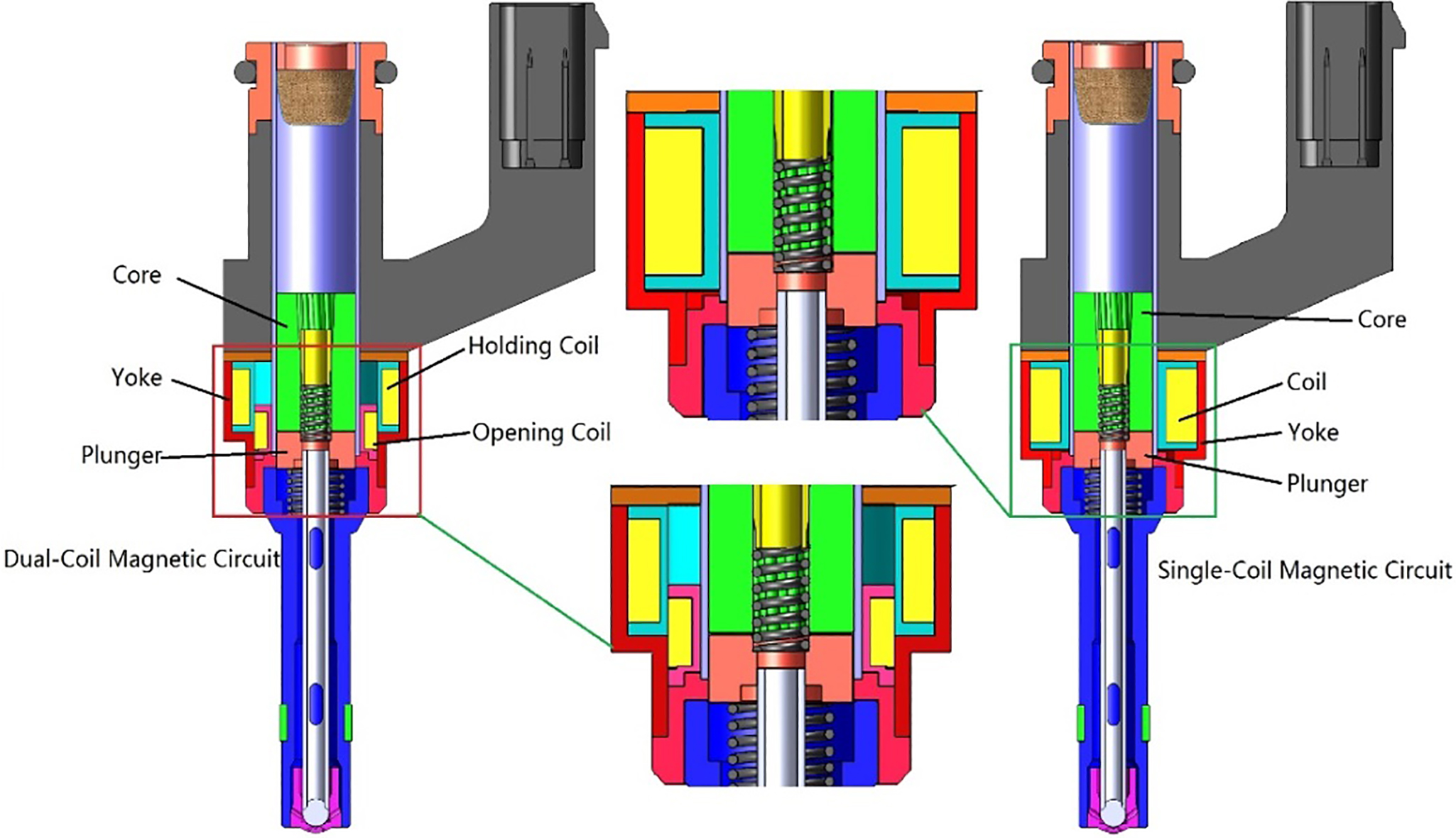
Driven strategies for the dual-coil and single-coil DISI injector.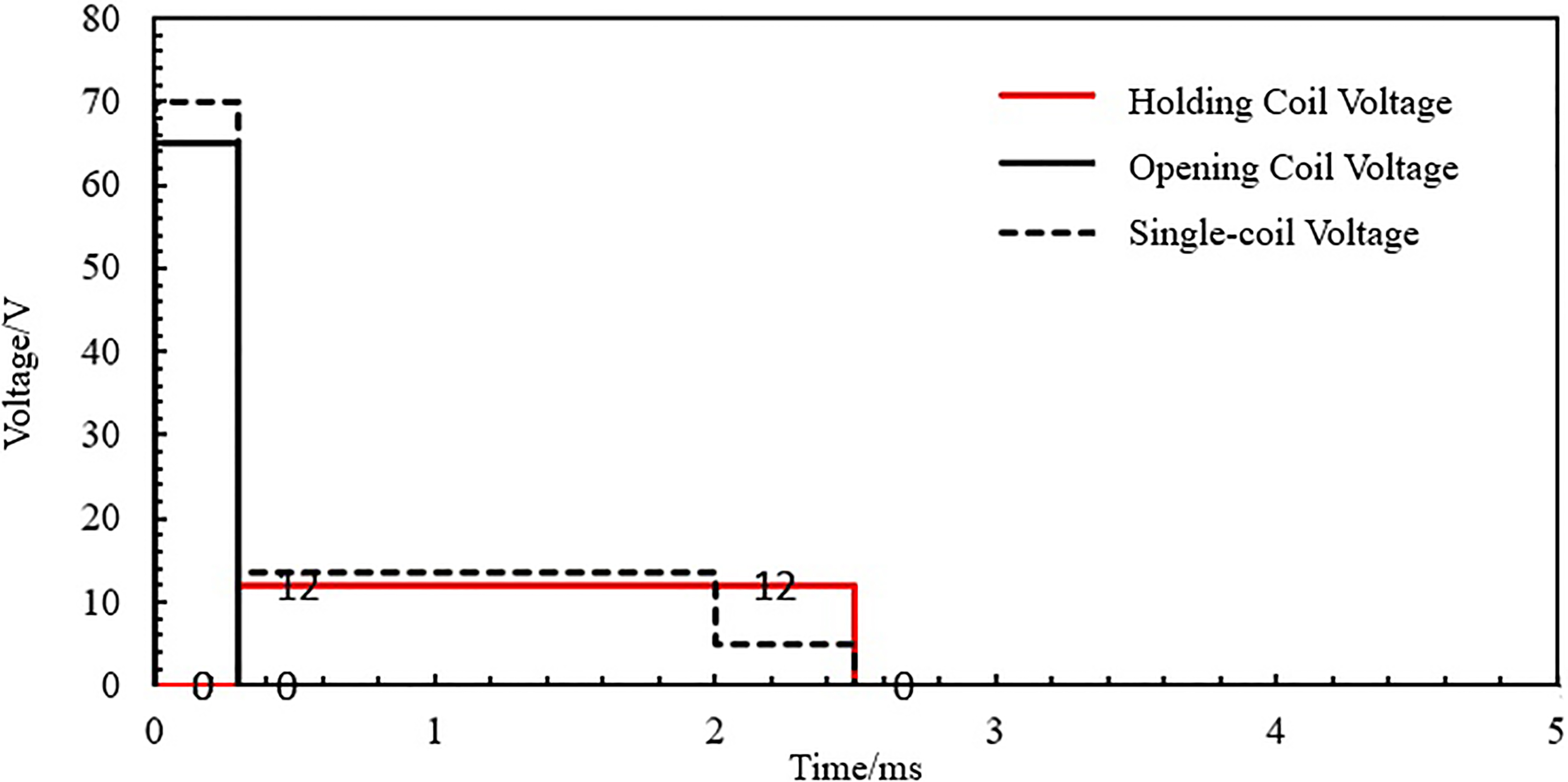
The injector coil is designed based on the battery-voltage-driven system. The opening coil is operated at 65 V for 0.3 ms, and holding coil is operated at 12 V for 2.2 ms. Before the dual-coil injector can be applied to a practical DISI gasoline engine, counter-measures against variations in battery voltage and harness resistance are needed. The dual-coil injector ensures reliable fuel injection and optimizes the flow characteristics by controlling the opening coil energization time in accordance with changes in the battery voltage, harness resistance and fuel pressure. To be more specific when the battery voltage drops, harness resistance increases or fuel pressure increases, the opening coil energization time should be prolonged. The control of the opening coil energization time and fuel injection signal compensation needed to make the injector suitable for practical use [9].
Figure 2 demonstrates the voltage driven strategies of the dual-coil and single-coil DISI injector. It apparently can be seen that the three stages is used at the single-coil DISI injector. The voltage is boosted to 70 Volts at the peak stage for 0.3 ms, and then the voltage is dropped to 14 V for 1.7 ms as holding voltage. Finally the voltage is dropped to 5 V for 0.5 ms. The strategy of the three stages is very complicate. However, the driven strategy of the dual-coil DISI injector has two stages. The opening coil is operated at 65 V for 0.3 ms, and then holding coil is operated at 12 V for 2.2 ms. This means the driven strategy of the dual-coil DISI injector is much simple than the single-coil DISI injector.
For the solenoid DISI injector, the magnetic circuit can be simplified as shown in Fig. 3. With the knowledge of Maxwell equation, the magnetic circuit of Fig. 3 and the corresponding equivalent circuit can be calculated identical to an electrically excited magnetic circuit. The magnetic flux density within the soft-magnetic circuit can be expressed as:
Where,
Equivalent circuit of the solenoid valve.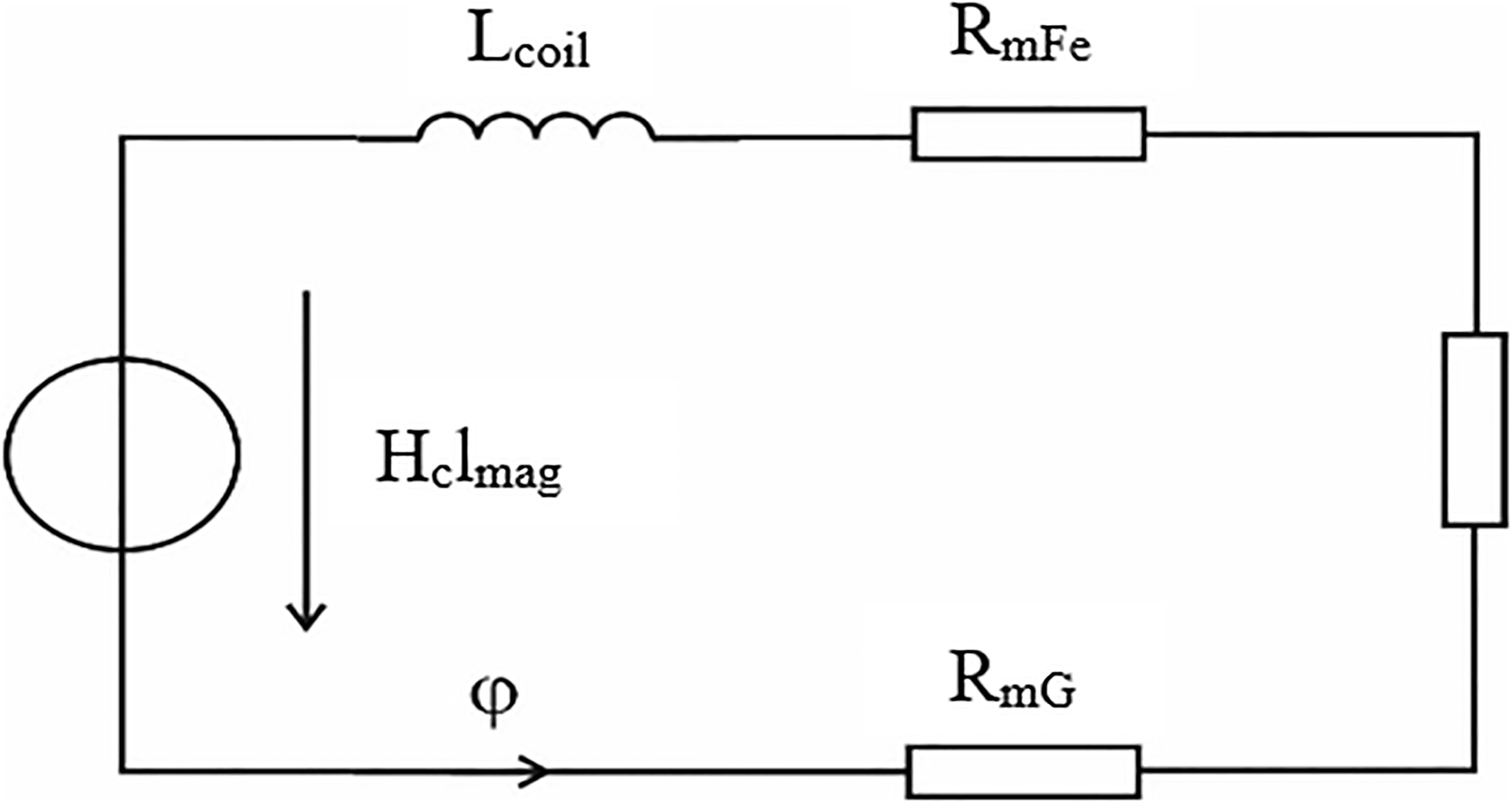
For the given magnetic circuit, the resistances
And then the flux density can be expressed as:
Equation (3) states by the factor
Simulation parameters
The commercial software Ansoft Maxwell is implemented to simulate the electromagnetic characteristics of the ultra-high speed solenoid injector. In order to ensure the accurate of the simulation results, the real parameters are taken as the boundary conditions for the simulation. The simulation parameters are listed in Table 1.
Simulation parameters
Simulation parameters
The simulation model is simplified to save computation cost, the simplified model and grid can be seen in Fig. 4. The total mesh cell number is about 50,000 which can satisfy the accuracy demands of simulation [10].
Mesh grid of the dual-coil and single-coil DISI injector.
The performances comparison of the dual-coil DISI injector and single-coil DISI injector are analyzed by the FEM (Finite Element Method) based on the Ansys Mexwell code. The magnetic flux, magnetic flux density and total loss distributions are analyzed by the counter images. The changes of current, magnetic force, plunger position, eddy current loss and solid loss over time are analyzed as well. The interaction of these parameters will be introduced in detail.
Magnetic flux distributions in the magnetic circuit.
In this investigation, the detailed analysis of magnetic field is provided to study the relationship between the magnetic circuit and key parameters. The magnetic line of flux is a virtual line which used to describe the magnetic field. Figure 5 shows the magnetic flux distribution at
Figure 6 shows the distribution of the magnetic flux density of the two kinds of DISI injector at
Magnetic flux density distributions in the magnetic circuit.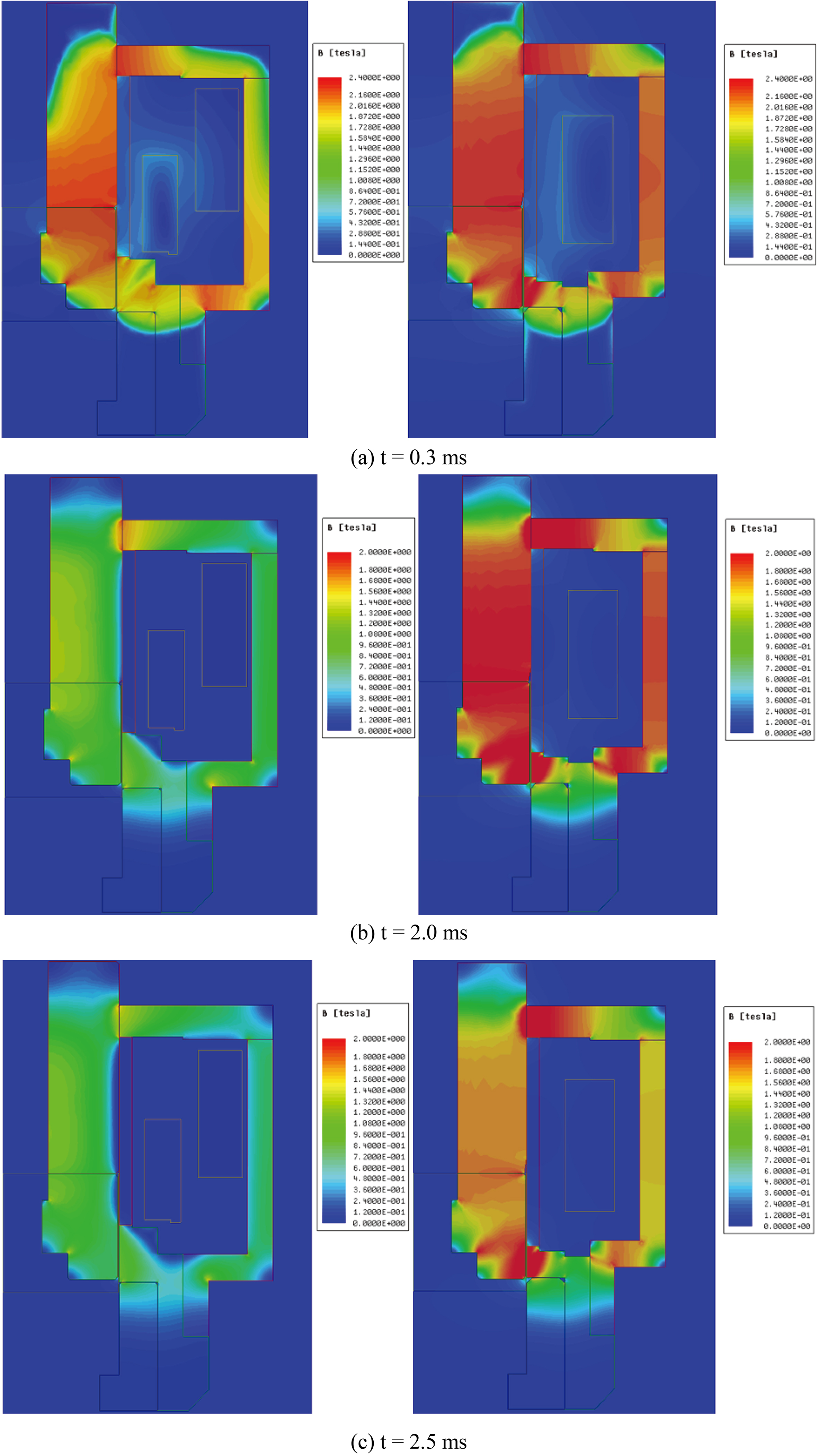
Total loss distributions in the magnetic circuit.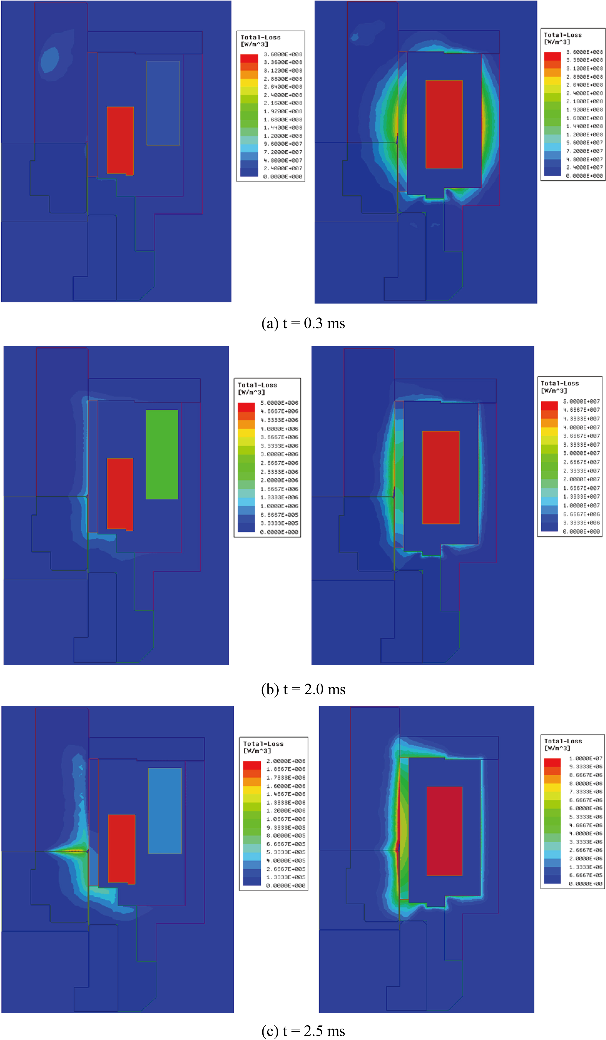
Current loss curves in the coil.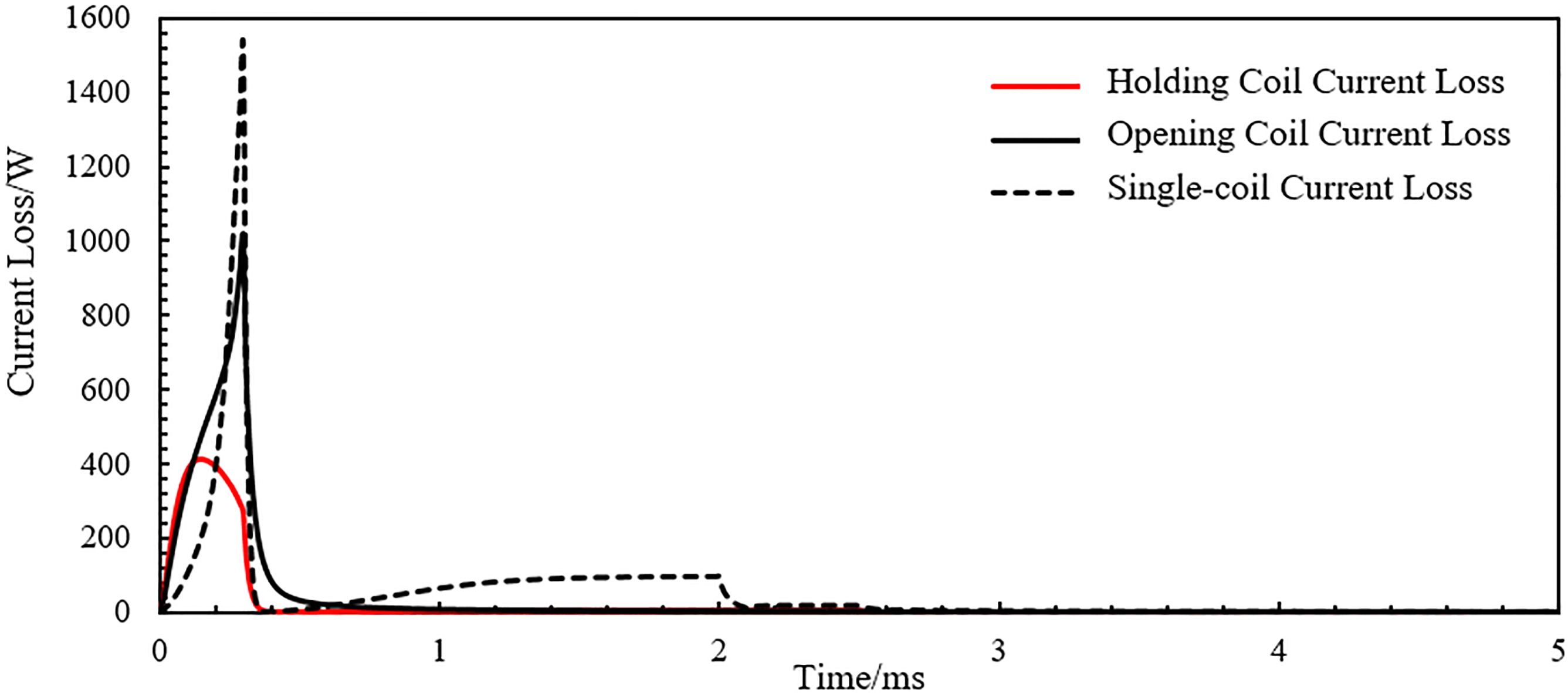
Eddy current loss curves.
The images of the total loss distribution show in Fig. 7. At
From the total loss analysis, the rationality of the magnetic circuit structure and driven strategies can be evaluated at the stage of the injector conception design through the FEM simulation. Simultaneously, the simulation results can also be utilized to guide the products design and performances prediction.
Figure 8 depicts the current loss of the single-coil DISI injector and dual-coil DISI injector over time. The current loss is one of the most important loss in the magnetic circuit of solenoid valve, and about 70% electric energy converts to thermal energy via the current loss. Therefore, the energy dissipating rate can be reported from the current loss. For the single-coil DISI injector, the peak current loss exceeding 1.5 kW much higher than the dual coil DISI injector 1.0 kW. This means at the opening stage, more energy is needed for the single-coil injector. Because the current loss cannot be used for injector, and the heat which generates from the current loss can cause the temperature rising and reduce the comprehensive performances of the solenoid injector [12]. Therefore, the current loss should be kept at the lowest level in driven circuit.
Eddy current loss is generated by the alternating current and it is also proportion to the frequency. For the transient electromagnetic field simulation, the eddy current loss cannot be neglected. Figure 9 indicates the eddy current loss curves of the two kinds of DISI injector over time. Although the eddy current loss is very low compared with other losses in the magnetic circuit, it still plays a crucial role in the magnetic circuit. Because it is the unique parameter relate to the frequency and skin effect. Figure 5 has been analyzed the distribution of the lines of magnetic flux caused by skin effect. Here the quantitative analysis of eddy current loss can be used to explain how the skin effect influences the performance of the injector. For the single-coil injector the highest current loss takes place at
Solid loss curves.
Figure 10 shows the solid loss of the two kinds of DISI injector. It is not difficult to see that the highest solid loss of the single-coil DISI injector is close to 400 W. At the holding stage it is still about 200 W, however the dual-coil DISI injector is about 250 W. Because the solid loss represents the resistive loss in the magnetic circuit, its value is proportional to the integral of the current density in the magnetic circuit. Therefore, the solid loss is directly relate to the current density. This means higher current density results in higher solid loss. Apparently, solid loss is the opposite to the requirement of solenoid valve design. For the dual-coil DISI injector, the solid loss is reduced under the condition of ensuring the current density.
To understand the different performances between the single-coil DISI injector and the dual-coil injector, several experiments have been undertaken. The objective of this section is to present the instrumentations and facilities used to specifically study the dynamic response observed in the transient laser displacement sensor.
Experimental setup.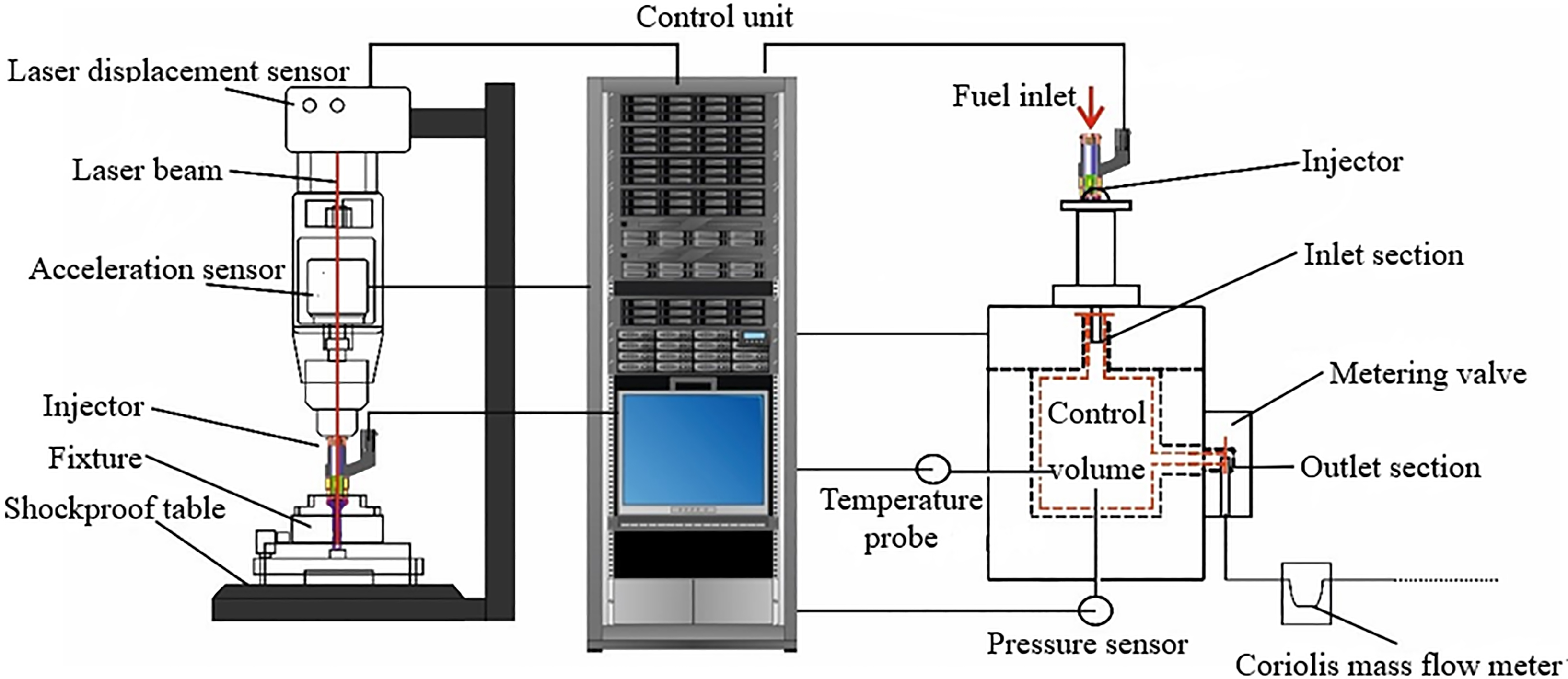
The actual motion and flow rate of the injector are measured by the experimental equipment shown in Fig. 11. This system can be used to measure the dynamic response and flow rate. The transient laser displacement sensor (Keyence LK-H025) is used directly to test the displacement curve of the armature. The measurement range of transient laser displacement sensor is
Figure 12 shows the current curves of the single-coil DISI injector and dual-coil injector. It can be seen that the current rise rate of the opening coil current of the dual-coil injector is much faster than the single-coil injector, despite the peak current is less than the single-coil injector. This indicates that at the opening stage, the magnetic flux density of the dual-coil injector will rise faster than the single-coil injector, and then the magnetic force is stronger, at last the opening delay is shorter. At the holding stage the current in the single-coil DISI injector is much higher than the dual-coil injector, however at this stage the plunger doesn’t move. This means except the work used for plunger attracting, the other energy is wasted to generate heat. At the closing stage the current in the single-coil injector is still much higher, and the higher current will generate higher force which will delay the injector closing. Therefore, the dual-coil injector has faster dynamic response and less power losses.
Current curves of the single-coil and dual-coil DISI injector.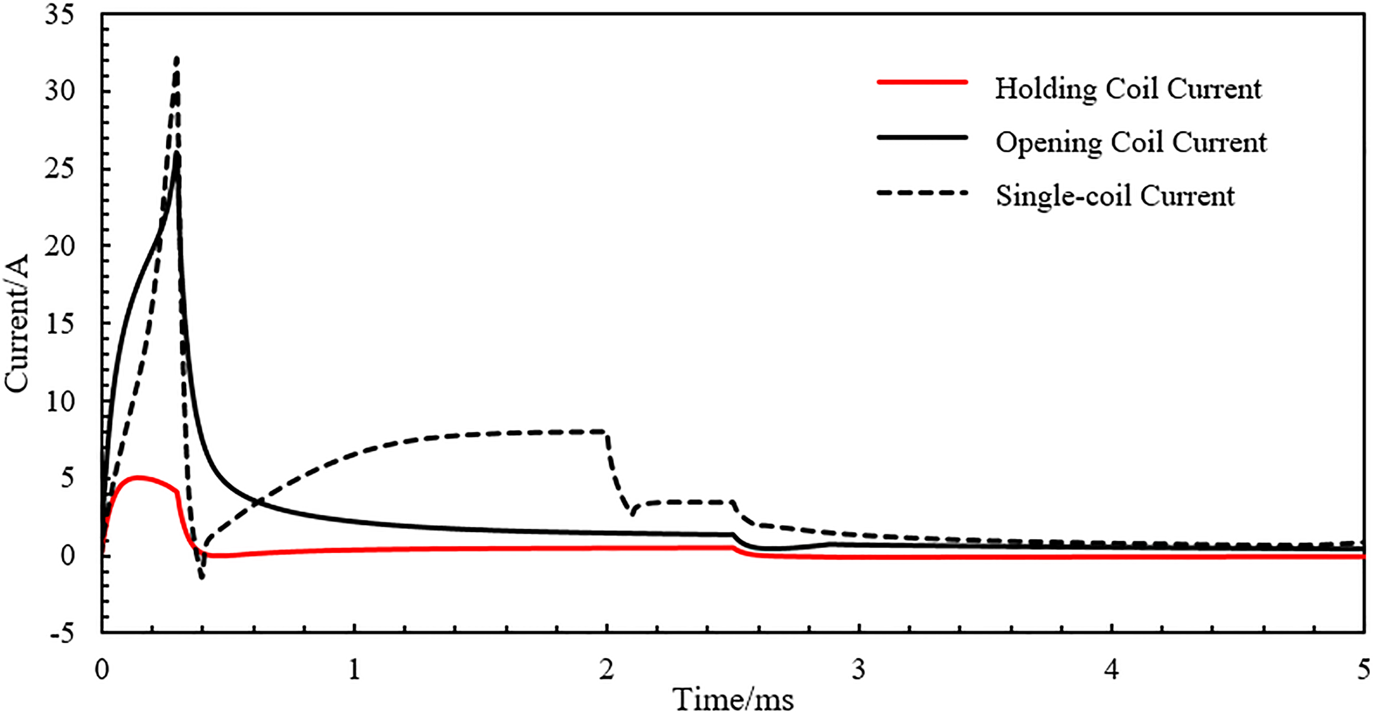
Note that the plunger position test is under no-fuel condition, because the laser cannot be used when there is fuel in the injector. Figure 13 shows the comparison of the single-coil and dual-coil DISI injector. According the previous analysis, it is not difficult to understand that the opening delay and closing delay of the dual-coil DISI injector is much less than the single-coil injector. Especially at the closing stage, the closing delay of the dual-coil DISI injector is about 0.15 ms shorter than the single-coil injector. The high dynamic response performance of dual-coil injector has some benefit for the DISI engine, including to improve the accuracy of the fuel injection rate, easily achieve multiple injection and reduce the emission.
Plunger position of the single-coil and dual-coil DISI injector.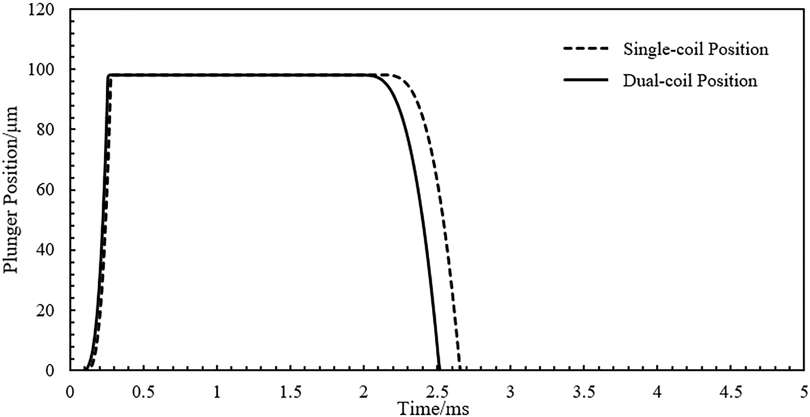
Figure 14 depicts the magnetic force of the single-coil and dual-coil DISI injector. One thing must to be clarified that the magnetic force shown in Fig. 14 is not the real force measured directly, and it is calculated from the acceleration and current based on Maxwell equation and Newton’s second law of motion. Although the driving voltage of the dual-coil DISI injector is lower than the single-coil DISI injector, the peak force is higher. The results prove that the dual-coil DISI injector has less power losses. At the closing stage the magnetic force of the single-coil injector acts on the plunger is still very high and almost 30% higher than the dual-coil injector.
Magnetic force of the single-coil and dual-coil DISI injector.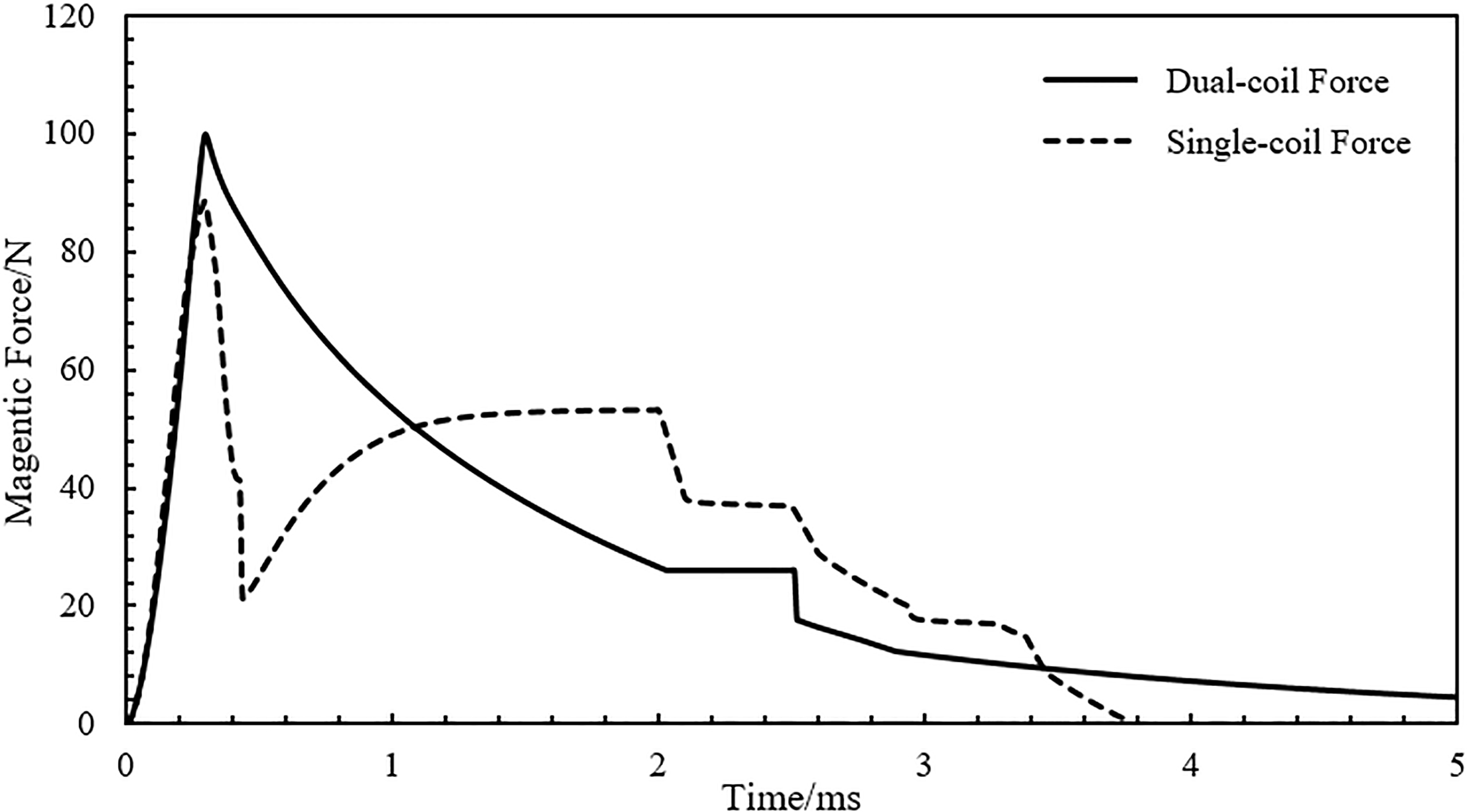
The shot-to-shot flow rate of the DISI injector is measured by the Mexus 2.0 GLD. This system is basically composed of a unit detector, a Coriolis mass flow meter and a standard rack with the necessary electronic. Figure 15 shows the flow rate of the single-coil and dual-coil DISI injector. The six holes nozzle is used in this experiment, and the fuel pressure in rail is 20 MPa. The results indicate that the flow rate is directly relate to the plunger position and dynamic response. The dual-coil DISI injector has shorter hydraulic delay than the single-coil DISI injector.
Flow rate of the single-coil and dual-coil DISI injector.
A novel dual-coil DISI injector was designed and analyzed in this investigation. The performances of the dual-coil and single-coil DISI injector were investigated based on the FEM simulation and experiments. The relevant physical effects were considered in this investigation. The major conclusions can be summarized as follows.
A novel concept of dual-coil DISI injector based on vehicle battery-voltage-system was investigated in our work. A multi-signals driver was designed to drive this new kind of injector. The mathematic models of the electromagnetic, mechanical and power losses were established, as well as the coupling parameters. The finite element method for electromagnetic field was used to simulate the magnetic flux, magnetic flux density and power losses distribution. These parameters were used to evaluate the performances of the solenoid injector. The eddy current loss, solid loss and total loss, simultaneously, the current curves and dynamic response were also calculated to analyze the comprehensive performances of the solenoid injector. The performances of the dual-coil and single-coil DISI injector based on these parameters were analyzed. The results of the comparison indicated that dual-coil DISI injector has better performances than the single-coil DISI injector on power losses and dynamic response. The total power losses was reduced about 30%. The opening delay was reduced about 5%, and the closing delay was reduced about 40%. Therefore, the dual-coil DISI injector has a great potential to applicate on the DISI engine to improve its comprehensive performances. The experiments were taken account to validate the simulation results. The current, plunger position and flow rate were measured directly by the laser displacement sensor and shot-to-shot flow rate device. The experimental results are in good agreement with the simulation results. Compared with the single-coil DISI injector, dual-coil DISI injector has faster dynamic response.
Footnotes
Acknowledgments
This work is supported by the National Natural Science Foundation of China (Grant No. 51275309). The Authors are all indebted to their generous support.