
Abstract
The physical state of laminated soft magnetic machine cores has high technical and economical relevance, in particular if advanced materials are involved, as in the case of transformer cores. Experimental analyses tend to be restricted to core surface regions due to the high expenditure of interior arrangements of sensors. Further, the latter cause inter-laminar spaces, as a reason of artefacts. The paper presents a completely novel sensor concept that avoids the above problems. A magnetic detection band of e.g. 1 m length consists of different kinds of sensors. They are arranged on a substrate foil by combined 2D/3D-printing, the total band thickness being below 100
Introduction
Cores of electric machines like transformers or motors are built up from laminated soft magnetic materials. Core masses may be up to hundreds of tons, and the corresponding magnetic performance shows high energetic and economic relevance. Thus, both industry and the public (see e.g. the EC initiative [1]) put strong effort on the optimization of core performances. This concerns optimum magnetic use of material in connection with 3D flux distributions. It also concerns a minimization of power losses. In more recent time, increasing interest is also given on reductions of audible noise, as emitted through magnetostriction and magneto-static forces. As a specific problem, most core designs represent complex 3D-systems [2], a pre-condition that is essential for effective optimizations.
Methodologies of modelling
A major tool for core optimizations is given by numerical modelling like MACC [3] or FEM. The latter is strongly complicated by pronounced multi-directional non-linearity of magnetic characteristics [4, 5, 6]. On the other hand, it proves to be highly effective for temperature distributions [7]. As an alternative, optimizations are supported in experimental ways. One option is the study of model cores which however involves problems of effective scaling-down. The second option is given by full-sized cores. however being complicated by restricted access to the core.
Experimental studies are focused on core surface regions that favor the attachment of sensor elements. However, as already stressed, a core tends to represent a 3D system which means that the interior physical performance may differ in significant ways. In the case of bulk cores, the only option for inner sensor application is to prepare thin channels into the core – or even through the entire of core. In [8], we reported a methodology where interior distributions of the magnetic induction
Inter-laminar sensors
In effective ways, the inter-laminar arrangement of sensors is possible for 3D analyses of inner distributions of temperature. Thermistors or thermo-couples can be arranged on selected lamination surface regions, e.g. to identify interior hot spots of the given core. The sensors also yield local losses, applying the rise of temperature method in the course of short-time magnetization.
Since decades, inter-laminar sensors are also used for the assessment of magnetic off-plane fluxes, as e.g. arising between individual packages of transformer core. So called frame coil sensors are established by thin wires that are fixed on lamination surfaces. For example, Fig. 1 (from [9]) depicts 29 sensors on selected surface regions of an interior transformer core layer, using wires of 150
Example for traditional arrangement of 29 induction sensors manufactured from 150 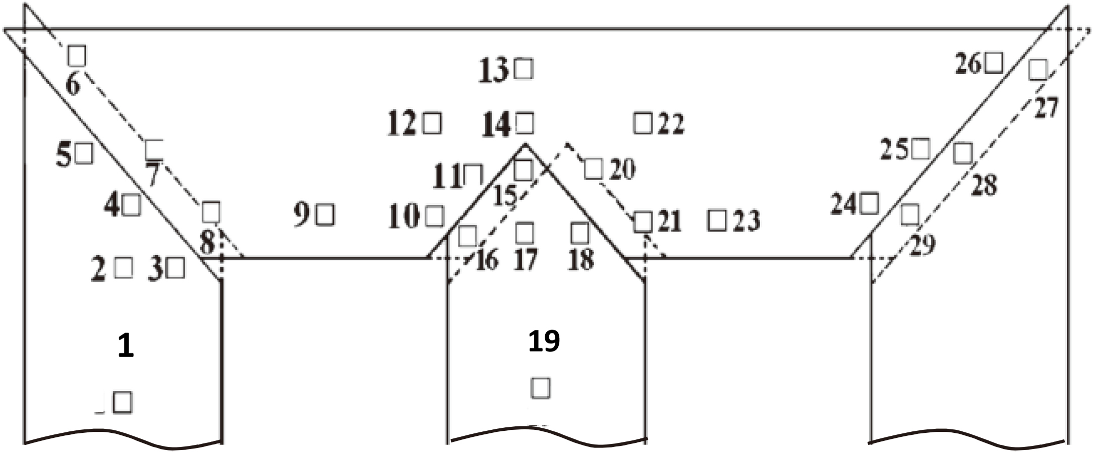
While being of highest interest, the inter-laminar measurement of in-plane components of the induction vector was not possible so far. The traditional way is to prepare search coils of thin wire through small holes drilled into individual laminations. Non-destructive methods were not reported so far – the present technique being a first approach.
The above mentioned sensors represent effective tools that yielded deeper understandings for the interior performance of machine cores. However, their application is characterized by major problems:
The thickness of sensor elements tends to be of an order that exceeds 100 The arrangement of sensors on defined surface locations of selected laminations involves high expenditure of manual fabrication work. The latter is increased by the arrangement of lamination within the core of machine. In practice, it proves to be difficult to avoid the damage of sensors and of the thin wires that are needed for contacts to electronics. The described procedures lack flexibility. In particular, the arrangement of treated laminations at other core regions proves to be complicated – or even impossible, in the case of regional variations of lamination geometry. As a specific problem, the traditional in-plane induction sensors are of destructive nature, as a source of artefacts.
The following describes a novel family of detection bands that avoids all four above mentioned areas of problems.
Global aspects of design
The basic idea of the novel sensor concept is illustrated by Fig. 2 for the case of a laminated transformer model core. As it is well known, industrial cores tend to exhibit a dozen of packages of different width (up to more than 1 m) in order to attain circular limb cross sections, in approximation. Here, a model core is depicted with just two packages P1 and P2, of different lamination width.
Schematic outline of two detector bands that are arranged in a model transformer core (e.g. 1 m 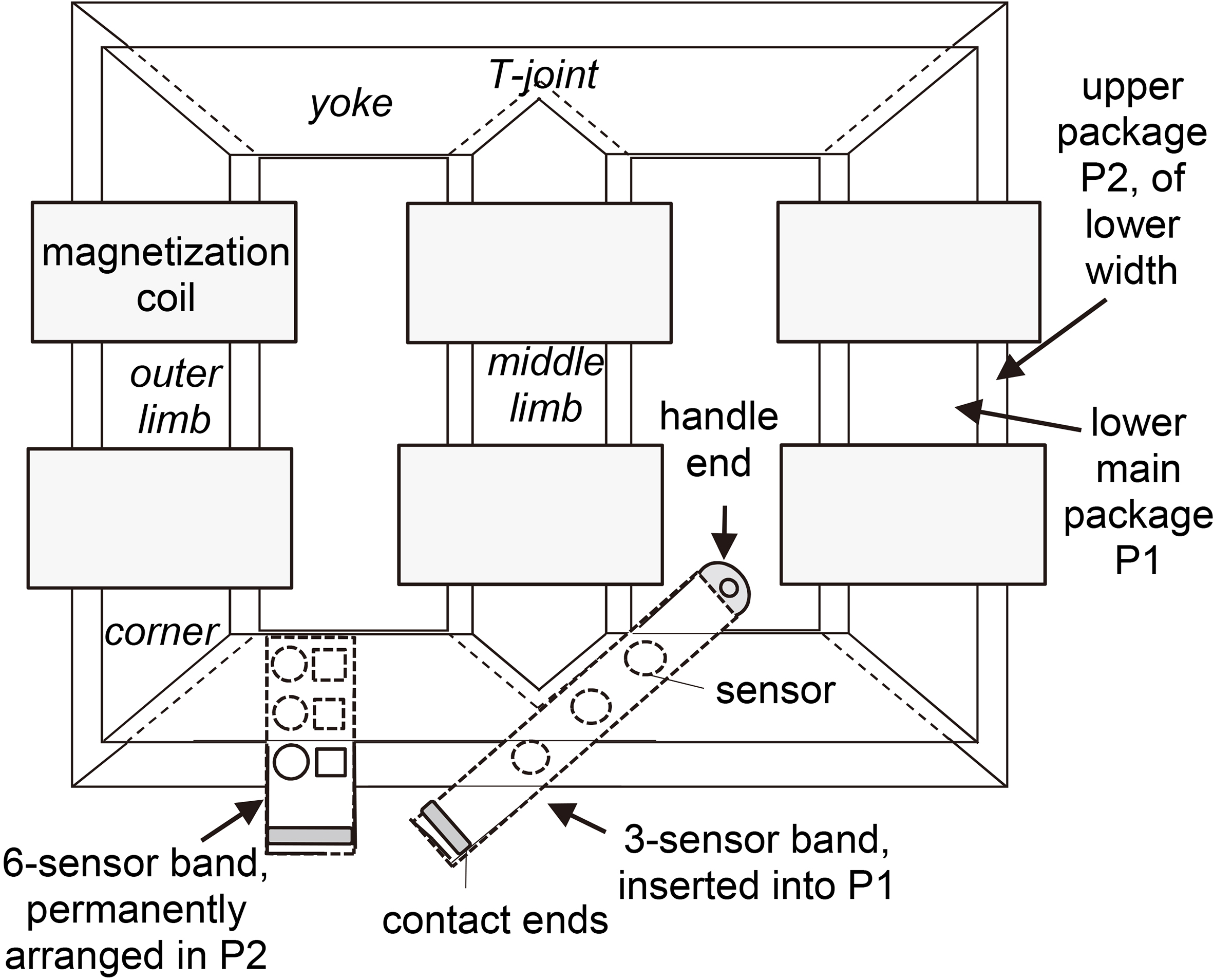
The figure indicates two types of detector bands. The left one is a permanent one that is arranged in defined ways on a selected lamination surface, during assembling of the core. It can be slightly fixed by thinnest agglutination, before it is permanently located through pressure of core clamping. The right band illustrates a temporarily located band. After short-time release of clamping, its sensors are positioned by the help of handles as given by the band ends. Measurement is performed after re-clamping. Finally, according to so far experience, many courses of re-positioning are possible. It should be mentioned that a given band may comprise different types of sensors, for multi-parametric analyses.
Further above, four problems of conventional sensors were listed. They are considered by the novel methodology in the following ways:
The sum thickness of novel magnetic detection band is well below 100 On a substrate foil of ca. 20 The band can be placed at different regions, and it can be moved. It also can be left within the machine core, without affecting its performance, e.g. for diagnoses, years after core production. Non-destructive detection of in-plane flux is possible.
A bit more in detail, magnetic detector bands are manufactured by the already mentioned 3D-assembler (Fig. 3). It exhibits a large printing platform of about 1200 mm length and 800 mm width. This allows for high band lengths that ensure that the band ends remain outside the investigated core for free contacting and handling. Conductive sensor elements are printed e.g. with carbon material by means of an extruder with a nozzle of e.g. 100
Concept of 3D assembler for automatic manufacturing of detector bands.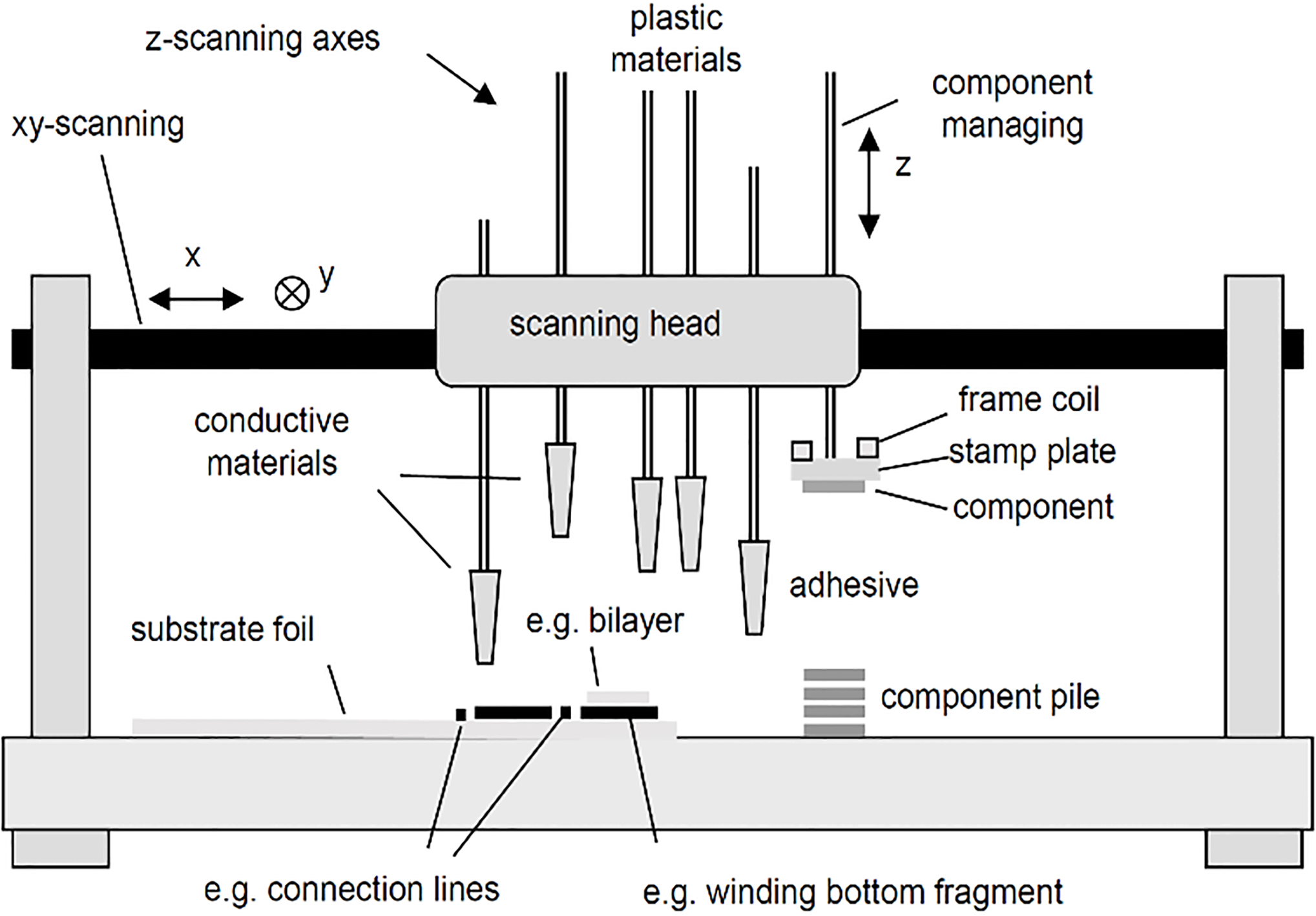
The type of substrate foil differs according to the given sensor type. Specific demands concern magnetostriction sensors were foils of sufficient elasticity are needed. On the other hand, minimum over-all thickness is needed for off-plane induction sensors. Attempts to print frame coils on plastic foils of just 10
As general demands, the foil should be thin, even and robust. In optimum ways, this is fulfilled by ca. 20
Further down, Section 3.2 describes novel in-plane induction sensors in detail. All other so far prepared sensor types are based on well known physical principles. Off-plane induction sensors follow the frame-coil principle [9] through a conductive meander layer, the main challenge being minimum sum thickness (see Section 3.1). Thermal thermo-couple sensors [12] exhibit a contact region of two conducting layers of conductive inks, the challenge being to rise sensitivity. Strain sensors show conductive meander-bands on a rubber substrate [13], the main problem resulting from non-linear performance.
Two very specific sensor types need the incorporation of thinnest soft magnetic ribbons with print-on windings. This concerns vibration sensors that are based on a curvature-sensitive bilayer of Fe-based amorphous ribbon and non-magnetic steel ribbon, as described in [14]. Further it concerns in-plane induction sensors. A completely novel sensor type with an incorporated nano-crystalline ribbon is described further down (Section 3.2) for the first time. So far, these ribbons are positioned in manual ways, with interruption of printing processes. However, an automatic incorporation is planned, as indicated in Fig. 3.
Induction bands are aimed on analyses of 3D magnetic flux distributions in machine cores. As a general demand for the mounted sensors, they should have considerably large effective areas, in order to average over a sufficient amount of grains. In particular, this is relevant for highly grain oriented SiFe sheets that may show grain sizes round 10 mm. 2D flux distributions within individual layers of soft magnetic laminations are studied by means of in-plane sensors. Inter-laminar
Off-plane induction sensors
Thinnest sensors for off-plane induction
Design of a detector band with sensors for off-plane flux density 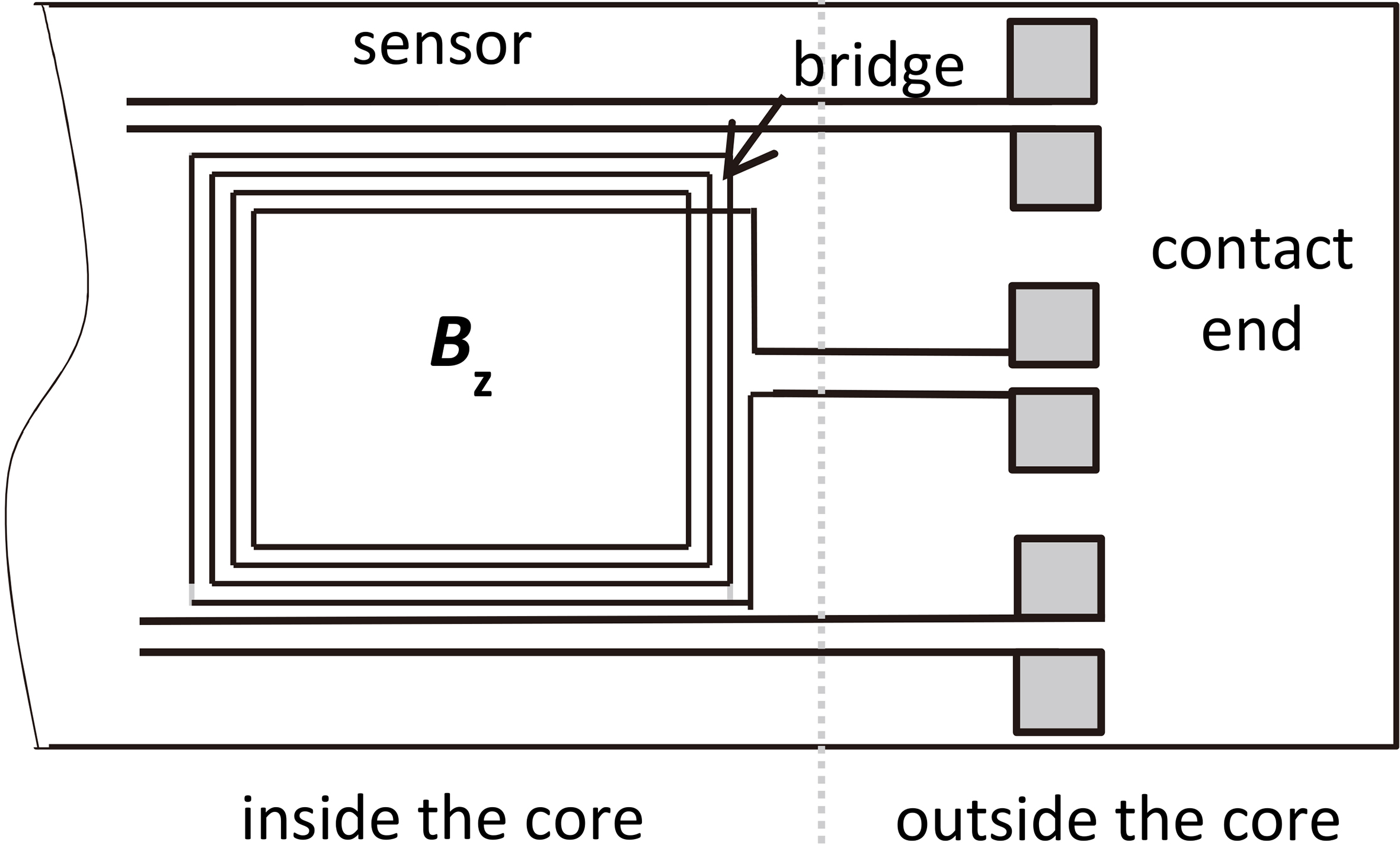
In contrast to the simplicity of the sensor principle, main problems arise from the request of very low sum thickness. As already mentioned, the effective spacing of magnetic laminations may be as small as 10
A correct measurement would need a substrate thickness below 1
As a compromise concerning thickness, first sensors were printed on 20
According to the above, increased inter-laminar spacing
As closer described in [18], the novel sensor type is based on the arrangement of a very thin soft magnetic ribbon between two core layers. It acts as a nucleus that is magnetized by the local inter-laminar field, analogous to a tangential field sensor. However, as is well known, in order to produce an effective signal, the latter would need about 1000 windings on a plastic carrier of millimeter thickness. For interior measurements, this is not acceptable since producing a large air gap. Here, we apply a nucleus the thickness of which does not exceed the order of 20
The principle of measurement is illustrated by Fig. 5a. It depicts local sections of three laminations of an inner region of a core, a sensor being arranged between the 2
In-plane induction sensors. (a) Principle of measurement, three laminations with an inter-laminar sensor seen from the side (notice: strong scaling differences). (b) Photo of a practical design of sensor on paper substrate, seen from above.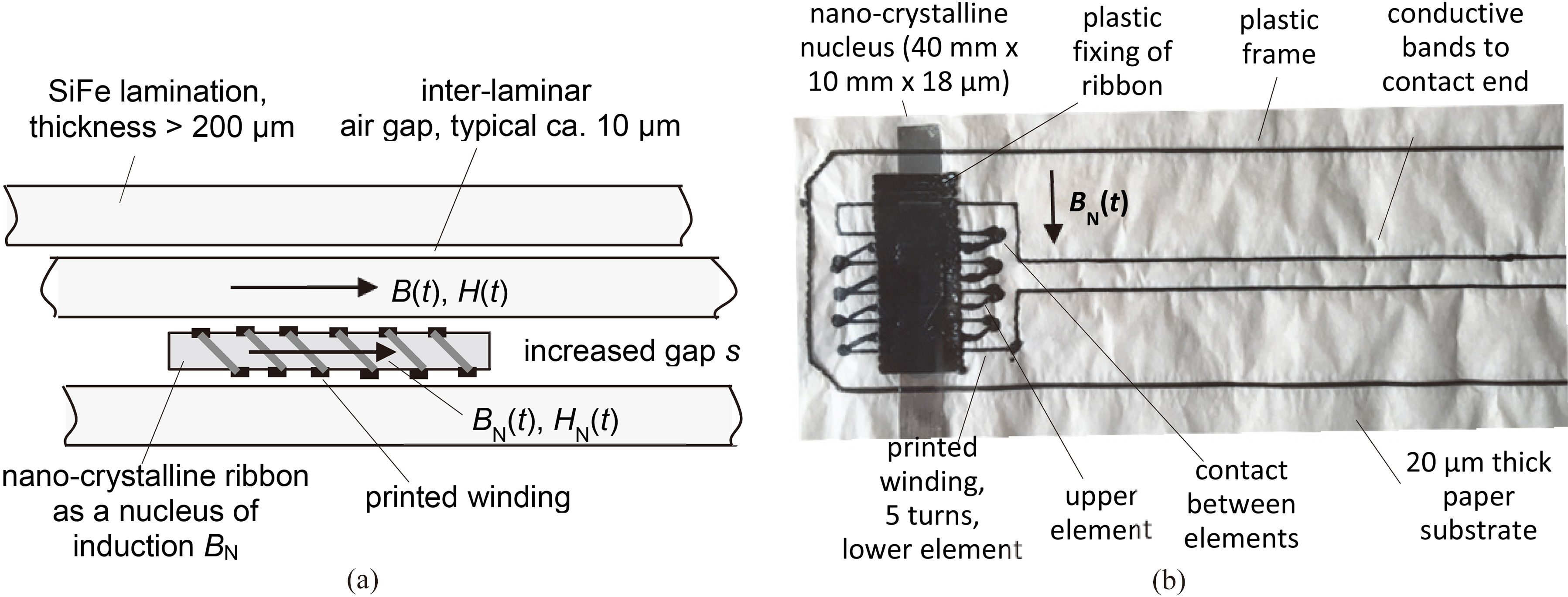
An appropriate material for nucleus manufacturing proves to be given by 18
In practice, core induction values should be detectable up to values
The above nucleus optimization yields an effective transfer of the to-be-measured induction
In our so far work, the function was assumed to be valid also for instantaneous values, according to
Figure 5b shows an example of a 20
Figure 6 shows a result of measurement in an outer limb region of a model transformer core magnetized with 1.7 T (according to Fig. 1, left from location 1). The course of time indicates strongly distorted induction
Result of measurement of in-plane induction 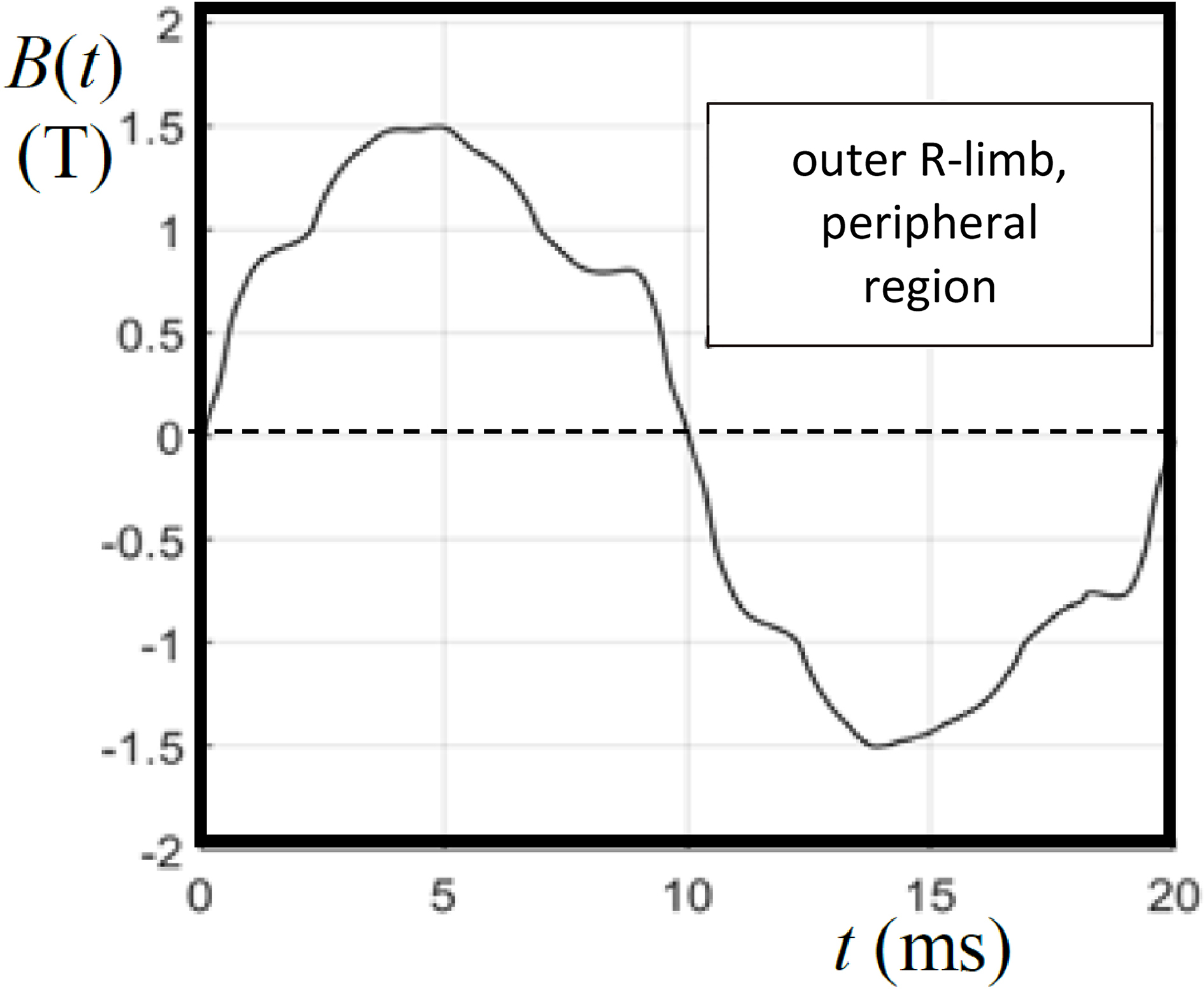
Here it should be stressed, that our earlier versions of induction sensors applied a nucleus either from crystalline SiFe material or from Fe or NiFe based amorphous material. All three cases are characterized by rather low permeability in the range of low induction values. This restricted the application to analyses of peak induction values, as a function of location. On the other hand, nano-crystalline ribbons, as here introduced for the first time, allow for the resolution of courses of time, due to very high values of initial permeability. Further, the ribbons are characterized by approximate zero-magnetostriction. This means that the performance in a clamped core is not influenced by mechanical stress, as a significant advantage towards the above mentioned crystalline or amorphous types of nucleus.
The above section was focused on the design of detector bands for local distributions of magnetic induction that tends to represent the most significant characteristic of a soft magnetic machine core. Industrial demand exists for a combination with sensors for local losses and core temperatures. Attempts are made to detect them by thermo-couple sensors, mounted on the same substrate. A spot of conductive print material is directly prepared on the substrate foil. A second spot of different composition is printed with slight overlapping, in order to establish a thermo-couple. Basically, this is a simple task. But in practice, the attained sensitivity proves to be influenced by many impact factors.
A further band type concerns distributions of mechanical core characteristics. Flexural vibrations can be detected analogous to in-plane induction, replacing the nano-crystalline ribbon by a magnetic bilayer ribbon that is incorporated according to Fig. 5. As closer described in [14], the latter compound consists of a highly magnetostrictive amorphous ribbon and a non-magnetic steel ribbon. Its task is to transfer curvature of the compound in tension of the amorphous ribbon. A second quantity concerns local magnetostriction of the core material, successful studies made by printing meander-like strain structures on already mentioned elastic substrates [13].
Provided that all above sensor types can be realized in reliable ways, the novel detection bands allow assessments of the most significant core characteristics for interior 3D analyses of laminated machine cores. Planning improved core designs, bands can easily be inserted in a given model core, and measurements can be taken after clamping. After repeated processes of de-clamping, the band positions can be modified for more detailed studies. As well, possibilities exist to modify core characteristics, like the design and pressure of clamps. After completion of study, the bands can be applied in other cores, if still being intact.
Further applications concern industrial full size cores. Bands can be located at selected regions during the assembling of a core. Clamping of the core favors the stable positioning of sensors in flat state. Bare band ends that act as mere handles for arrangement can be removed. On the other hand, measures have to be set to avoid that active contact ends remain without disturbance of core behavior. During normal, long-term core operation, the novel detection bands enable for the first time to study the “real” physical behavior of the finished product, without causing artefacts.
As a further industrially relevant aspect, further measurements are possible in the course of diagnostics for defects that may appear after years of core manufacturing. For example, this may concern anomalies of temperature distributions in the course of insulation defects, or inhomogeneous core vibrations in the course of mechanical defects.
As a main conclusion, magnetic detection bands can be placed into soft magnetic machine cores without affecting the physical state of core. Connections to electronics remain outside, through band lengths that can exceed one meter. Several sensors are arranged on the band by means of combined 3D/2D printing. This allows for rapid manufacturing of low costs. Sensors concern all significant physical core characteristics like magnetic induction and losses, temperature, as well as mechanical strain and vibrations. The total effective band thickness remains well below 100
Footnotes
Acknowledgments
The authors thank for support from the Austrian Science Funds FWF (project MagFoils No. P 28481-N30). They also acknowledge very valuable experimental work of M. Palkovits and G. Trenner.