
Abstract
The magneto-rheological damper (MRD) has been widely used to suppress shock and vibration, which has strong nonlinearities and electromagnetic interference (EMI) due to the displacement vibration, semi-active control strategy, excitation current and excitation coil. The transmission impedance of excitation coil should be determined and measured to calculate excitation current and design EMI filter, which can improve the MRD control effectiveness and mitigate EMI noises. However, the transmission impedance of excitation coil is active complex impedance, which can’t be determined by traditional passive impedance extraction method. To solve the problem, the transmission impedance model and equivalent circuit of MRD is proposed and analyzed. Moreover, a novel transmission impedance extraction method is designed to obtain the transmission impedance of excitation coil online. The theoretical and experiment results show that the transmission impedance of three ferrite core with different turns can be determined. The transmission impedance of Lord MRD RD-8040-1 can be obtained by employing the present method, which comply with theoretical results well. The transmission impedance of MRD at characteristic frequency is growing with excitation current increasing, which verify the MRD transmission impedance model and extraction method efficient and effective.
Keywords
Introduction
MR fluid was first proposed in 1948 by Rabinow [1, 2, 3], which with rheological properties can be changed subjected to the controllable direct magnetic field. It can be in place of the traditional hydraulic damper and considered as a new generation controllable damping device. MR fluids are composed of the low hysteresis, high permeability micrometer or nanometer scale ferromagnetic particles, non-magnetic liquids and stabilizer. Without the direct magnetic field, MR fluid can be categorized as Newtonian material, which exhibits high mobility, low apparent viscosity and a linear response. With increasing the direct magnetic field, the apparent viscosity of the MR fluid can increase in the millisecond 2 times or higher times. It exhibits low mobility and high apparent viscosity and can be categorized as Bingham material. Moreover, the changes in material properties are instantaneous, continuous and reversible, and the shear yield strength of the MR fluid is stably subject to magnetic intensity.
Considered as a new shock absorber, the magneto-rheological damper (MRD) consists of MR fluid, excitation coil, piston, diaphragm, accumulator and cable by Kim et al. [4] and by Yang et al. [5]. Depending on direct magnetic field and semi-active control strategy, the controllable MRD can output damping force, which has been widely applied in vehicle suspension, aerospace industry, rail transportation system and constructional system by Wang et al. [6], by Nam et al. [7] and by Daniel and Rolf [8]. Moreover, the conducted and radiated electromagnetic interference (EMI) are generated by the excitation current and MRD. However, the transmission impedance of excitation coil is nonlinear and affected by excitation current by Wang et al. [9] and by Priyandoko et al. [10]. As an active two-port network, the traditional passive impedance analyzer is invalid to measure the transmission impedance of excitation coil.
Nowadays, many researches have been carried out on active impedance extraction and measurement. The insertion loss method was proposed by Zhang in 2000 and by Zhao in 2015, which consist of series insertion loss method and parallel insertion loss method. Series insertion loss method is available when impedance under test is much greater than load impedance. Parallel insertion loss method can be employed when impedance under test is much less than load impedance. However, the accuracy of insertion loss method is affected by the coupling capacitor in measurement circuit, whereas the insertion loss method is invalid when impedance under test and load impedance are substantially equal. Dual current probes method was proposed by See and Deng [13] and by Tarateeraseth et al. [14], which can obtain the amplitude of impedance under test approximately based on spectrum analyzer. However, the phase of impedance under test can’t be obtained by dual current probes method, and there are some approximations and constraints in the formula derivation process. The dual standard resistance method with Levenberg-Marquardt’s algorithm was proposed by me in 2013 [15] and Chen et al. [16], which can determine the amplitude and phase of impedance under test. Nevertheless, the measurement accuracy is relevant to standard resistance and test circuit, and the measurement process is more complicated. Jiang and Wan in 2017 proposed a hybrid method based on adaptive cross approximation algorithm, multilevel fast multipole method and multilevel compressed block decomposition [17]. Although it can analyze the large-scale electromagnetic scattering and radiation problems, it is only theoretical calculations and electromagnetic simulations. Moreover, the analysis accuracy of hybrid method is affected by the actual active device and control circuit.
In conclusion, the methods above can the impedance under test, but there are still some problems to not be used for MRD, such as harsh restrictions, imaginary invalid, low accuracy, measurement complicated or offline. On basis of the acquired achievements about semi-active control and EMI noise of MRD [12, 15, 18, 19], transmission impedance model and equivalent circuit of MRD are proposed in the paper. Moreover, based on the two current probes and scattering parameter analysis, the transmission impedance extraction method has been designed with vector network analyzer, which can determine the transmission impedance of excitation coil effectively and efficiently. It establishes an important theoretical and practical foundation for the MRD semi-active control and electromagnetic interference noise mitigation.
Transmission impedance model of MRD
As shown in Fig. 1, with the increase of control current in excitation coil of the MRD, the magnetic intensity in the channel is strengthened and the drag force of MR fluid rises through the channel, which leads to the increase of the output damping force of MRD increasing. On the contrary, with the decrease of control current, the magnetic intensity in the channel is attenuated and the drag force is reduced, which leads to the decrease of the output damping force of MRD. Based on these characteristics and performance of the MR fluid and MRD, the output damping force of MRD can be controlled. Moreover, the performance is called semi-active control strategy because the output damping force is subject to the controllable MRD and the uncontrollable springs.
MRD structure & performance.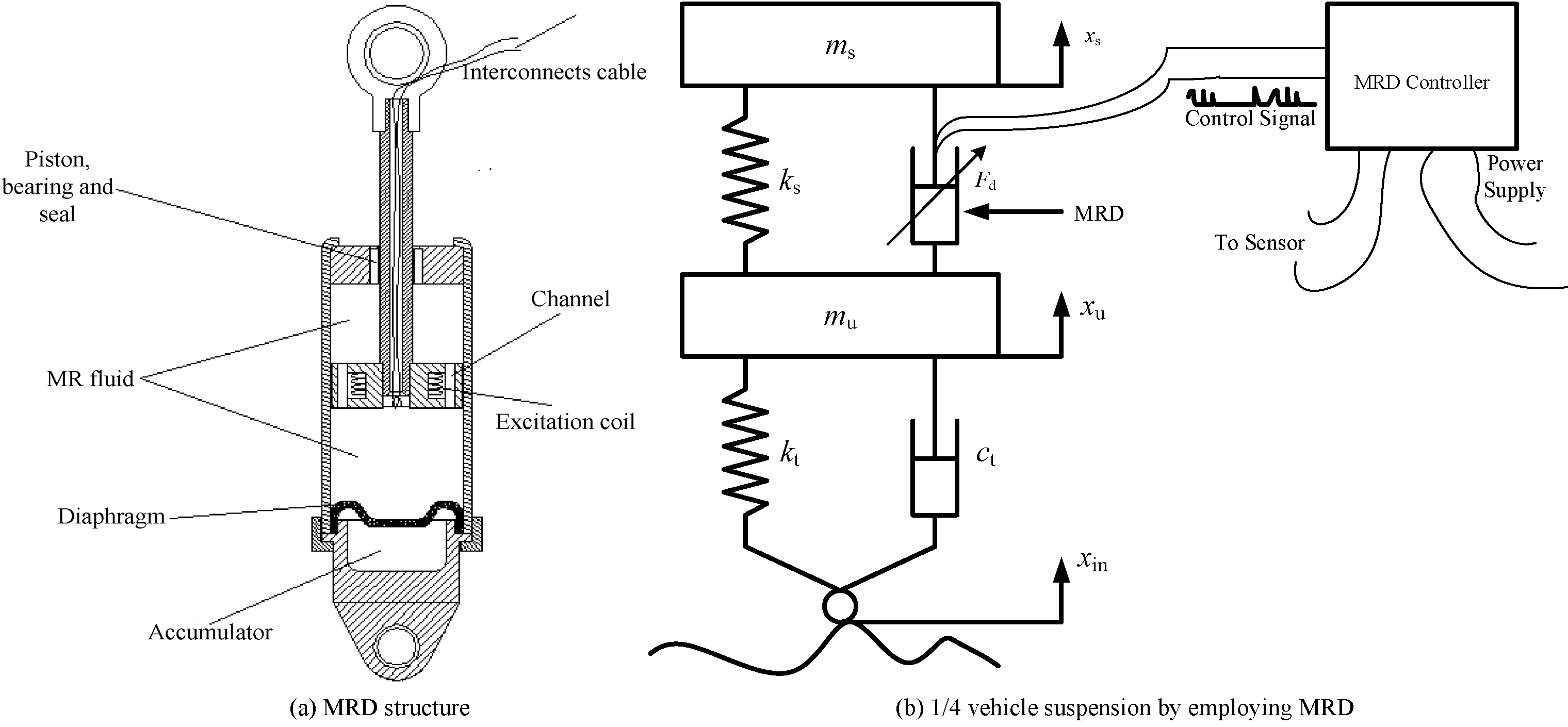
The excitation current loop includes in excitation coil and cables. The transmission impedance of excitation coil is nonlinear and altered with the excitation current. In high frequency, the circuit parasitic parameters should be concerned, such as parasitic capacitance, parasitic inductance and parasitic resistance. The transmission impedance model is established as shown in Fig. 2, where
Transmission impedance model of MRD.
Due to the transmission impedance model of MRD, the equivalent circuit can be obtained, as shown in Fig. 3, where
Equivalent circuit of excitation coil.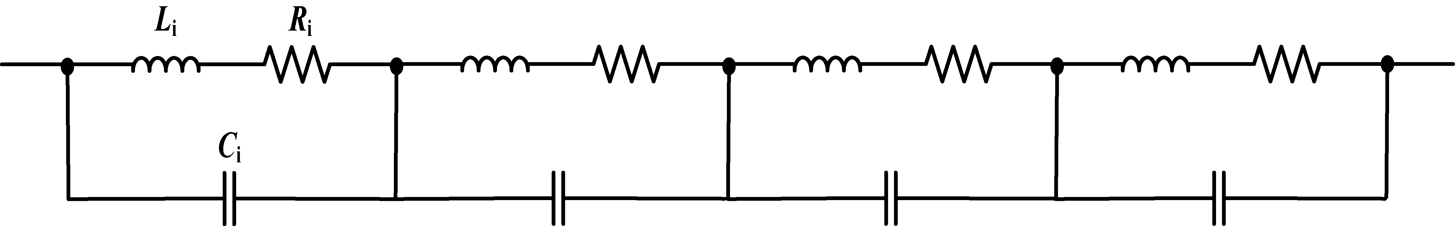
The MR fluids is uniform and stable in MRD, whose permeability and dielectric constant are constants. The parasitic capacitance, parasitic inductance and parasitic resistance per length are the same in excitation coil. Therefore, the simplified equivalent circuit of excitation coil can be established, as shown in Fig. 4, where
Simplified equivalent circuit of excitation coil.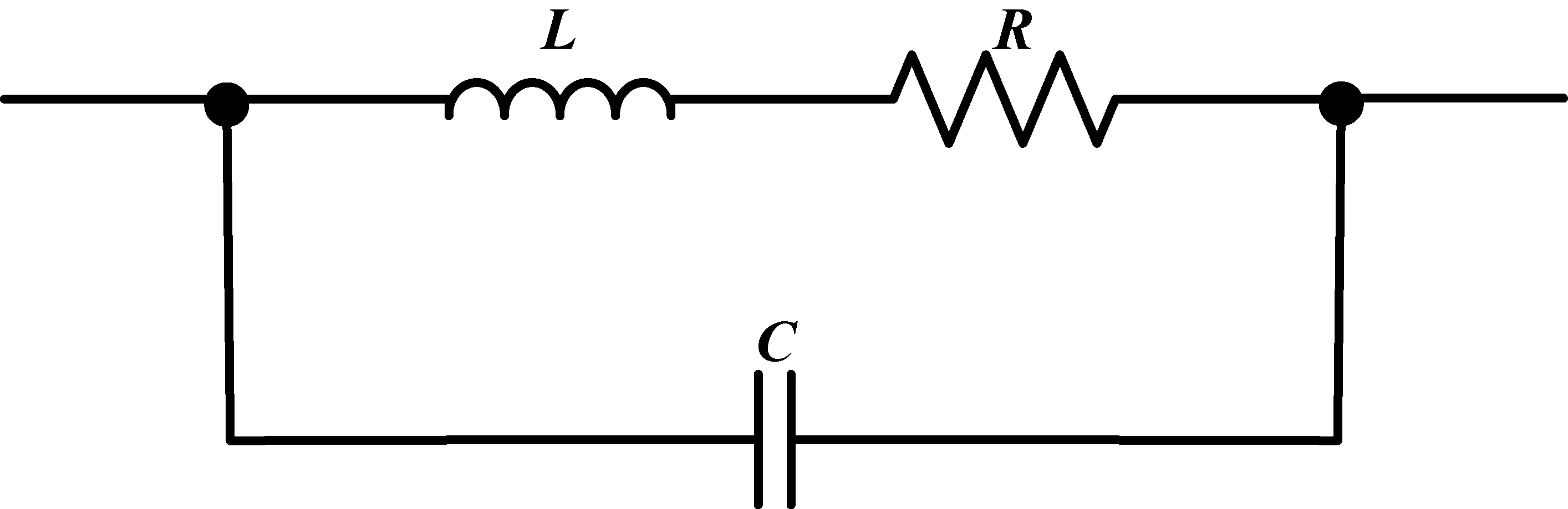
As shown in Fig. 4, the transmission impedance of excitation coil can be derived as
Where,
The Eq. (1) is expanded due to imaginary units and can be derived as
Where, the parasitic resistance, parasitic inductance and parasitic capacitance in simplified equivalent circuit of excitation coil can be obtained.
In high frequency, the parasitic resistance
The setup of transmission impedance extraction method has been designed, as shown in Fig. 5, where the vector network analyzer and two current probes are used.
The setup of transmission impedance extraction method.
Where,
Step 1, Short the
Where,
Step 2, Replace
Where,
Step 3, Measure
Where,
Passive ferrite core verification experiment.
Based on the Eqs (4) and (7) and Fig. 5, the transmission impedance under test
Verify experiment results of three passive ferrite core with different turns.
As shown in Eq. (8),
Active MRD transmission impedance extraction experiment setup.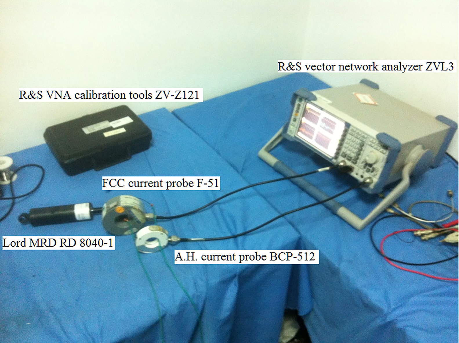
To verify the proposed transmission impedance extraction method, R&S vector network analyzer ZVL3, R&S VNA calibration tools ZV-Z121, A.H. current probe BCP-512, FCC current probe F-51 have been employed. The experiment included in passive ferrite core and active MRD (Lord RD-8040-1) excitation coil.
Passive ferrite core verification experiment
The Green, yellow and white ferrite cores, which are made of carbonyl iron powder-BASF, have been under test with different turns, as shown in Fig. 6. The relative permeability of green, yellow and white ferrite core are 75, 22 and 9. The outer diameter of three ferrite cores are 26.7 mm, 27.5 mm and 23.1 mm. The inner diameter of three ferrite cores are 18.8 mm, 19.4 mm and 15.2 mm.
The characteristic frequency of green ferrite core is about 10MHz with different turns, as shown in Fig. 7a. The characteristic frequency of yellow ferrite core are 22 MHz with 5 turns, 16 MHz with 10 turns, 8 MHz with 15 turns and 3 MHz with 20 turns, as shown in Fig. 7b. The characteristic frequency of white ferrite core are 1 MHz with 5 turns, 15 MHz with 10 turns, 5 MHz with 15 turns and 5 MHz with 20 turns, as shown in Fig. 7c. In addition, the step size of sweeping frequency is 1 MHz from 10 Hz to 10 MHz and 5 MHz from 10 MHz to 200 MHz, respectively.
Active MRD transmission impedance extraction experiment
Lord MRD RD-8040-1 has been used to determine the transmission impedance of excitation coil. The experiment setup is shown in Fig. 8.
The MRD transmission impedance of excitation coil has been measured by employing the present method with no excitation current, as shown in Fig. 9a and c. Based on the simplified equivalent models and Eq. (3), the MRD transmission impedance of excitation coil has been calculated with no excitation current, as shown in Fig. 9b and d. The experiment and theoretical results show that the frequency response and resonance point of MRD transmission impedance can be obtained well, where the impedance amplitude for experimental and theoretical result are 2.99 k
Experiment results of active MRD transmission impedance extraction.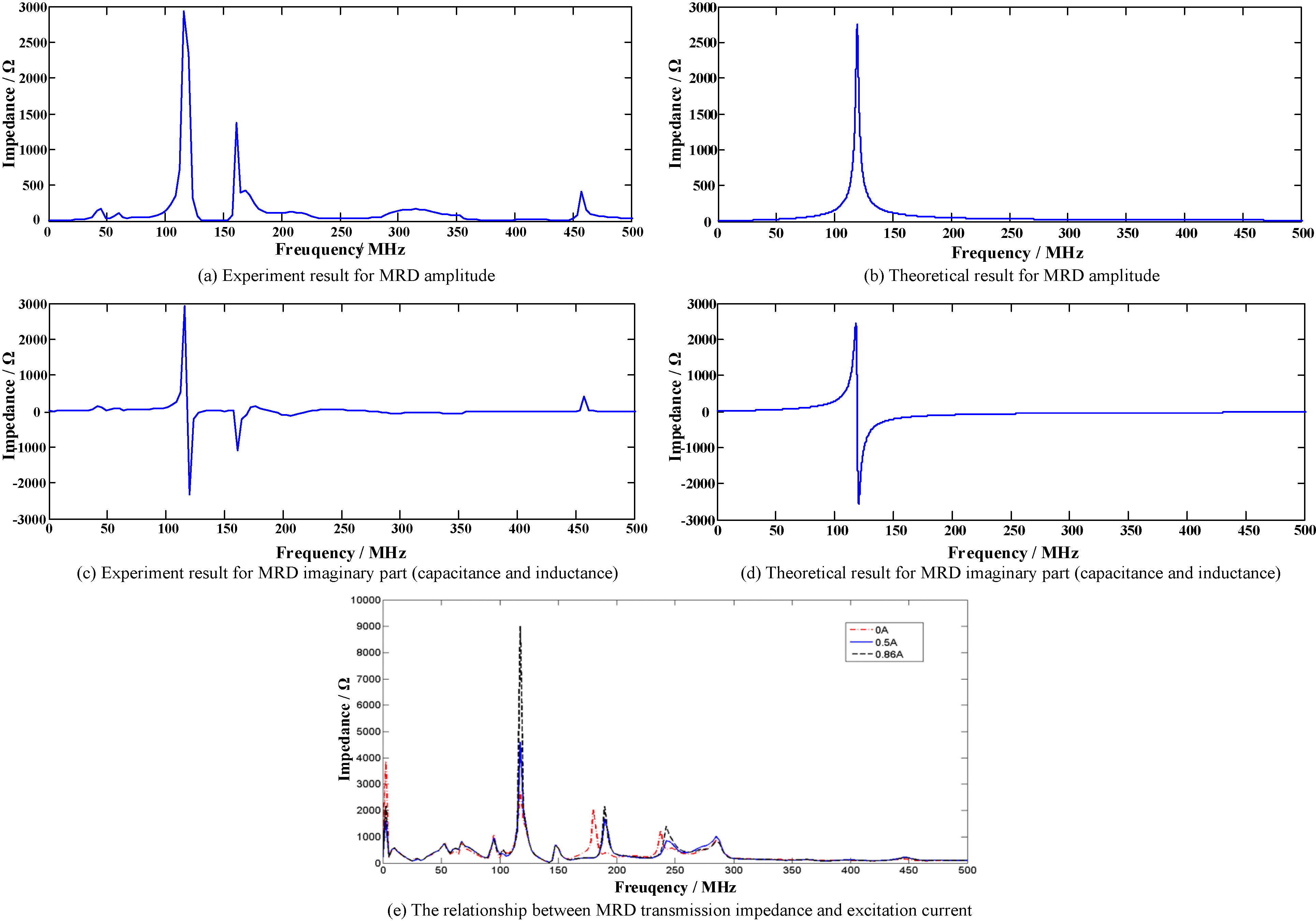
With the excitation current increasing, the flux generated by MR fluid particles is growing, which will cause MRD transmission impedance to increase. The simplified equivalent models and Eq. (3) are invalid to determine the MRD transmission impedance with excitation current. However, it can be obtained by employing the present method, which is growing with excitation current increasing at the characteristic frequency, as shown in Fig. 9e.
In this paper, the excitation coil and semi-active control of MRD have been analyzed, the transmission impedance model and equivalent circuit of excitation coil have been proposed, and a novel transmission impedance extraction method has been designed for MRD, which can determine the transmission impedance online efficiently and improve the semi-active control and EMI noise mitigation of MRD. The conclusions are in details as follows:
The MR fluid principle and semi-active control of MRD are analyzed. The transmission impedance model of excitation coil has been proposed without excitation current based on high frequency parasitic parameters. The high frequency equivalent circuit of MRD has also been established without excitation current. The transmission impedance extraction method of MRD has been designed by employing vector network analyzer and two current probes, which can obtain the amplitude and imaginary part of complex impedance online and comply with theoretical results well. Moreover, the relationship between transmission impedance and excitation current has been studied. Both theoretical method and experimental method can be used to determine MRD transmission impedance without excitation current. However, the experimental method can also be employed to obtained MRD transmission impedance with excitation current.
The theoretical and experiment results show that the proposed transmission impedance extraction method can obtain the online impedance under test. With the excitation current increasing, the transmission impedance of MRD at characteristic frequency is growing, thus it can support the development, application and safety and electromagnetic compatibility design for the MRD system.
Footnotes
Acknowledgments
This paper is supported by Project Supported by National Natural Science Foundation of China (51475246); National Natural Science Foundation of Jiangsu Province (BK20161019), University Science Research Project of Jiangsu Province (15KJB470011).