
Abstract
When large stroke of giant magnetostrictive actuator (GMA) is desired, it usually requires large number of turns in coil to generate sufficient magnetic field and therefore induce a considerable inductance in actuator. In this paper, a specific driving method is proposed for electro-hydraulic servo valve based on large inductance GMA. To begin with, a more reasonable model for the dynamics of driving coil is proposed and identified using Particle Swarm Optimization (PSO); then a specific half-SPWM driving mode is proposed taking advantages of this considerable inductance. The multi-coupled model for the overall servo valve is set up and simulated in a joint environment of Simulink and AMESim; a prototyped switching converter based on Micro Controller Unit (MCU) and Insulated-Gate Bipolar Transistor (IGBT) is developed, a series of displacement and power tests are conducted. Both simulation and test results verify the advantages of our design, compared with continuous driver the proposed method drives the coil with less power consumption and a more compact structure; compared with traditional Sinusoidal Pulse Width Modulation (SPWM) driving mode, this method generates a smoother wave using less switch number and less switching losses.
Introduction
Giant magnetostrictive material (GMM) denotes a smart alloy which generates considerable magneto-elastic strain under influence of an external magnetic field [1]. Compared with other functional materials such as piezoelectric materials and shape memory alloys, GMM are distinguished in its considerable energy density, wide frequency band and low hysteresis. All these exciting characteristics make the GMM based actuators (GMA) a thriving transducer in development of novel fluid control devices such as electro-hydraulic servo valves (GMA-EHSV), oil injectors [2, 3] and micro pumps [4, 5].
However, fluid control devices, especially the electro-hydraulic servo valves (EHSV), usually require their transducers provide sufficient stroke all through the working frequency band. Given the limited strain of smart material, GMM bar in such transducers should be fabricated very long. In this case, large scale coil is required to provide enough exciting magnetic field for GMM bar, which makes the inductance of GMA in mH level. This characteristic makes some challenges for the development of EHSVs based on GMA (GMA-EHSV).
The first challenge cares about the rising time of coil current. Although the magnetic field (
The second challenge cares about the development of specific power supply for GMA, the high inductance of GMA increases the difficulties in development of specific power supply system. The traditional power supplies for GMA are mainly continuous devices such as power amplifier and programmable constant current sources. In such a device, the mains AC power is converted by a transformer. After rectification, filtering and voltage/current feedback, a desired output could be achieved. The technology for such continuous supply is mature. The voltage or current output of the device could reach high precision and stability without significant current ripple. Wu and Zhu developed a high precision NC constant-current source for GMA, it provides current from 0 to 2.048 A with 0.5 mA step value in static driving mode, the current ripple is less than 0.25 mA [8]; Li et al. developed a servo amplifier for GMA based servo valve, the nonlinearity is below 3% and response time is 3 ms when 2 A current is applied [9]. However, continuous devices usually require bulky power converters and filtering capacitances, increasing the total volume of the device; the amplification thyristors, such as MOSFET, are working in a linear amplification states, increasing the power consumption and degrading the transfer efficiency. When large current is required by GMA-EHSV, the heat dissipation of power supply has to be considered seriously [10]. In this case, bulky fans and cooling fins have to be embedded which makes the device consume more energy and space. In addition, for highly inductive load such as GMA, the apparent power delivered by continuous system is much larger than the real power under high frequency circumstance [11]. This usually makes a lower power factor and impendence mismatch. In order to lower the driving voltage and save energy, Li et al. developed an energy-efficient, continuously adjustable constant current source using power operational amplifier, which is more energy efficient than MOSFET [12]; Sadighi developed a local three-phase excitation system for GMA, he employed 24 axial serial coils excited independently by eight power MOSFETs. The system is mastered by a complicated control board based on DSP and a 3-line-to-8-line decoder, the motor demonstrated a 45 mm travel range under a consumption of 95 W [13, 14]. Recently, the technology of solid-state switches is significantly advanced and these switches such as insulated-gate bipolar transistor(IGBT) and integrated-gate commutated thyristor (IGCT) have led to compact and reliable converters [15]. Compared with continuous sources, this converter uses sinusoidal pulse width modulation (SPWM) technology and is much simpler in topology structure, therefore more readily to be structural compatible with load devices; The components in switching sources are working in a switching state. This will help to reduce the power consumption and increase the power factor, especially for inductive load such as GMA [16].
In this paper, we respond to the mentioned two challenges in the following ways. To begin with, a fully dynamic model of GMA-EHSV is established from applied voltage. The solenoid circuit is equivalent as a LRR model since the parallel resistance is concerned, and the parameters of LRR model are identified using particle swarm optimization (PSO) method.
Furthermore, concentrating on the specific impendence property of GMA-EHSV, we develop a small and power saving switching converter for GMA-EHSV. The basic idea of this design is by taking advantage of, rather than overcoming, the large inductance of GMA. In the converter, a microcontroller unit (MCU) is employed to generate specific pulse series; a H-bridge IGBT circuit transferred the MCU signal as applied voltage to the GMA coil. Lastly, through the dynamic modeling of GMA-EHSV under switch driving mode, we propose a modified half-SPWM (H-SPWM) driving mode for GMA-EHSV exciting. This mode uses the large inductance of GMA to generate a smoother wave using less switch numbers.
The structure of this work is outlined as follows: Section 1 concerns the introduction of current driving method for GMM applications and outlines the main work of this paper; Section 2 covers the dynamic modeling of GMA-EHSV, with its coil model analyzed and identified using PSO; Section 3 denotes the circuit and driving mode design of a novel PWM switching power based on MCU and IGBT; Section 4 covers the multi-coupled simulation technology of GMA-EHSV driven by proposed power supply, the advantages of our novel driving mode are discussed; Section 5 covers the displacement and power test of GMA using in EHSV driven by our proposed power supply, the advantages of our driving method are exhibited through the comparison with traditional power supply and SPWM converter. The primary conclusion and innovations are summarized in Section 6.
Structure of GMA-EHSV.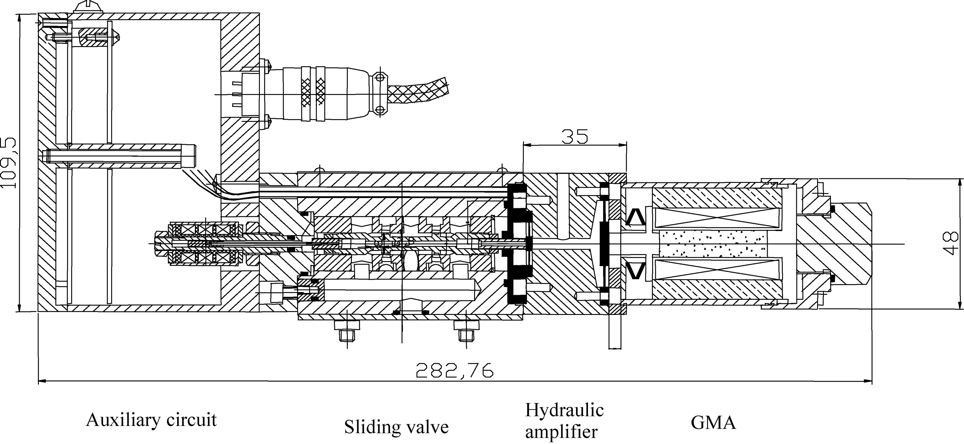
Structure and working principle
Figure 1 denotes the structure of GMA-EHSV. There are mainly four parts of the above valve, namely: GMA, hydraulic amplifier, sliding valve and the auxiliary circuit. Its movement during a duty circle could be generally described as follows: to begin with, coil within the GMA is excited, driving the GMM rod to elongate; then this tiny stroke is amplified by a novel hydraulic amplifier, enlarged enough to drive the spool moving inside the sleeve to control the flow rate. The details of design for each part could be referred to our former works [17, 18].
Electrical model
The basic model for a solenoid is the serial inductor and resistor, which is exhibited as Fig. 2a. In this model, the practical solenoid is regarded as a serial connected inductor and resistor. This model is valid for most of the regular cases when the driving signal is concentrated in low frequency domain, with a simple iron core or without core in the solenoid. However, this simplified model usually fails to count for high frequency cases. Therefore, two modified equivalent circuit for GMM valve solenoid are employed, the first one includes the parallel capacity as Fig. 2b, which is induced by different layers of the coil; the second one considers the parallel resistor of the multi-layer coil.
Identification result
Identification result
Three equivalent circuits for solenoid.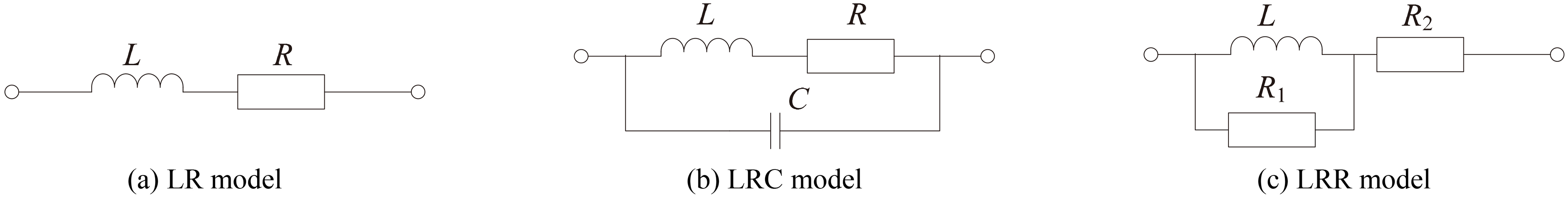
The equivalent impedances for the above three models are derived as
In order to setup a valid impedance model, we identify the parameters respectively of the above equivalent circuits. Particle swarm optimization (PSO) is employed in this paper to conduct the identification. Compared with traditional optimization method, PSO are distinguished for its global optimization property; Compared with other evolution method, such as generic algorithm and difference evolution, PSO are simpler in structure and easier to converge [19]. The details of governing equation and structure of PSO iteration could be referred to our former works [18, 20].
The identification result is exhibited as Table 1. With the parameters substituted into Eq. (2.2), the test results are compared with different equivalents curves as Fig. 3.
Impendence characteristics of test and of different equivalent models with identified parameters.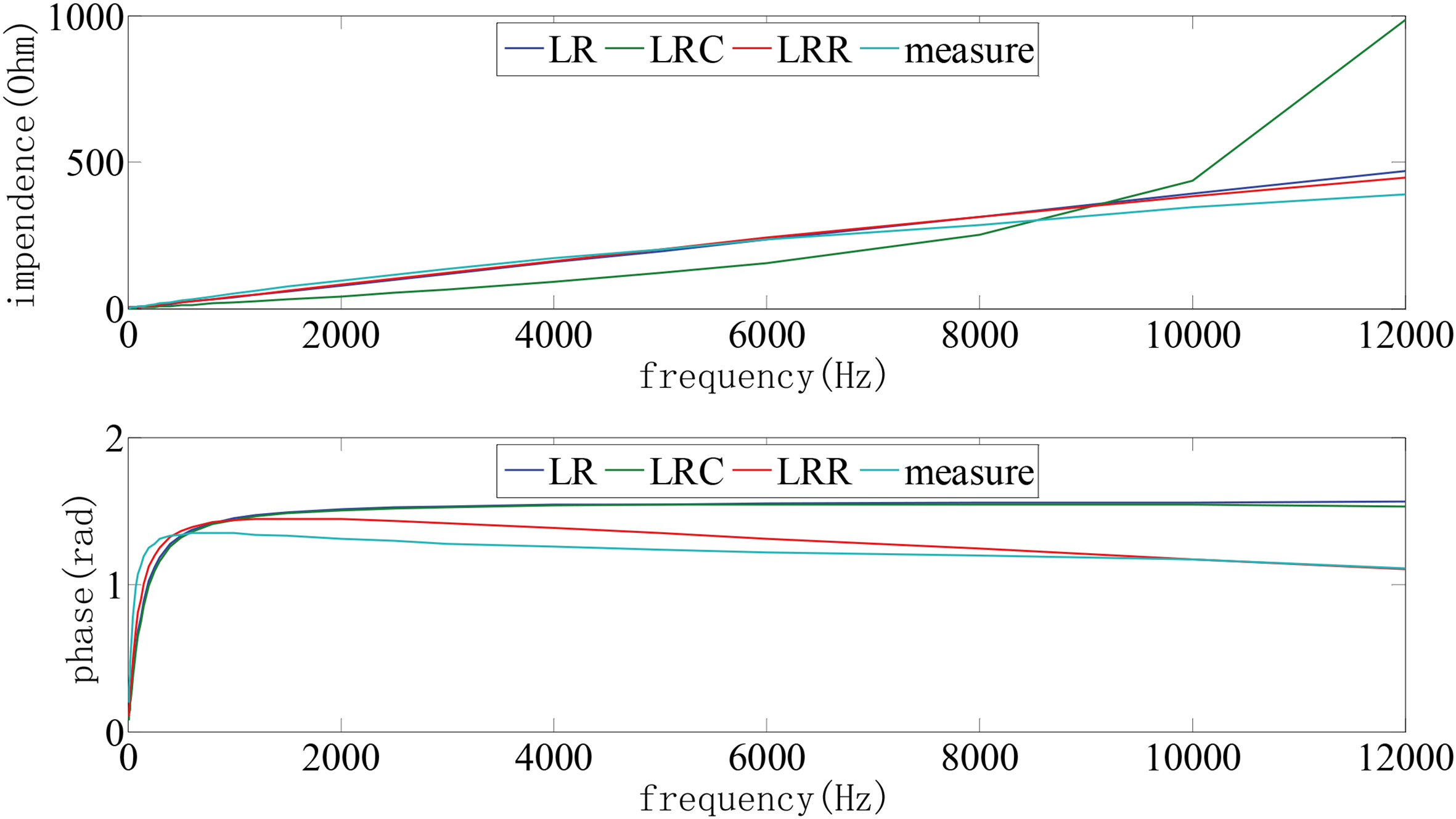
The impendence and phase error curves of different equivalents are exhibited as Fig. 4.
Identification errors of different equivalent models.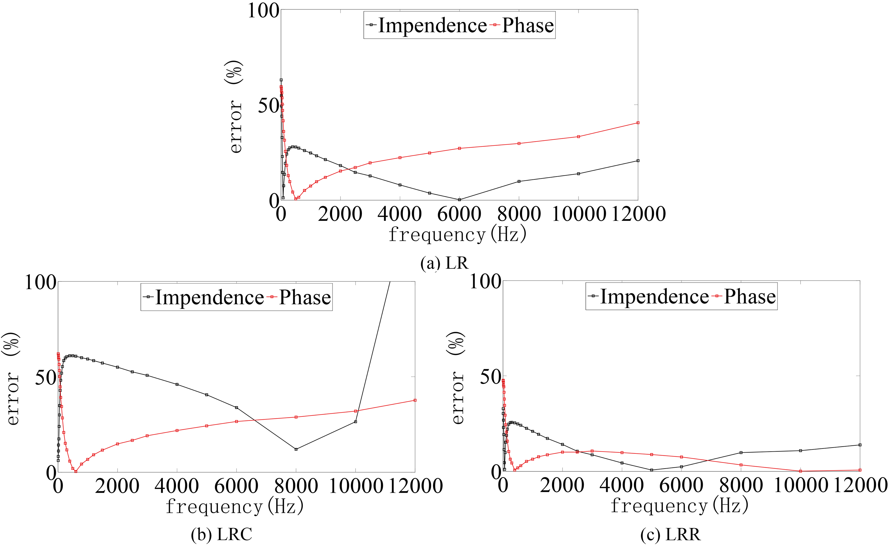
Figures 3 and 4 indicate the proposed LRR model is more accurate in description of the coil dynamics, especially when the driving frequency is high. Therefore, in the rest of this paper, we employ this model to cover the impedance model of driving coil.
Based on the identified model of driving coil, the relationship between applied voltage and driving current could be expressed as the following transfer function.
The exciting magnetic field
The relationship between magnetic field
The magnetostriction of GMM rod could be described in a polynomial model [2]
the vibration model of hydraulic amplified GMA could be expressed by the following transfer functions [18]
Take the spool driving force
Based on the above equations, a diagram is employed to cover its multi-coupled dynamics of GMA-EHSV as Fig. 5.
Multi-coupled modeling of GMA-EHSV.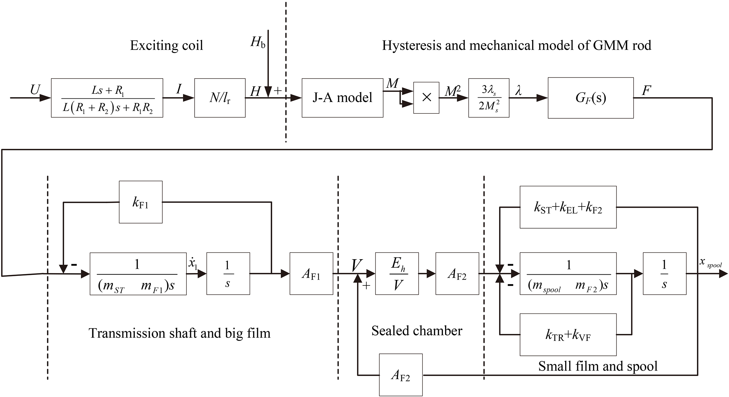
Circuit design
The layout for the proposed power supply is exhibited as Fig. 6.
Working principle diagram and photo of switching power supply.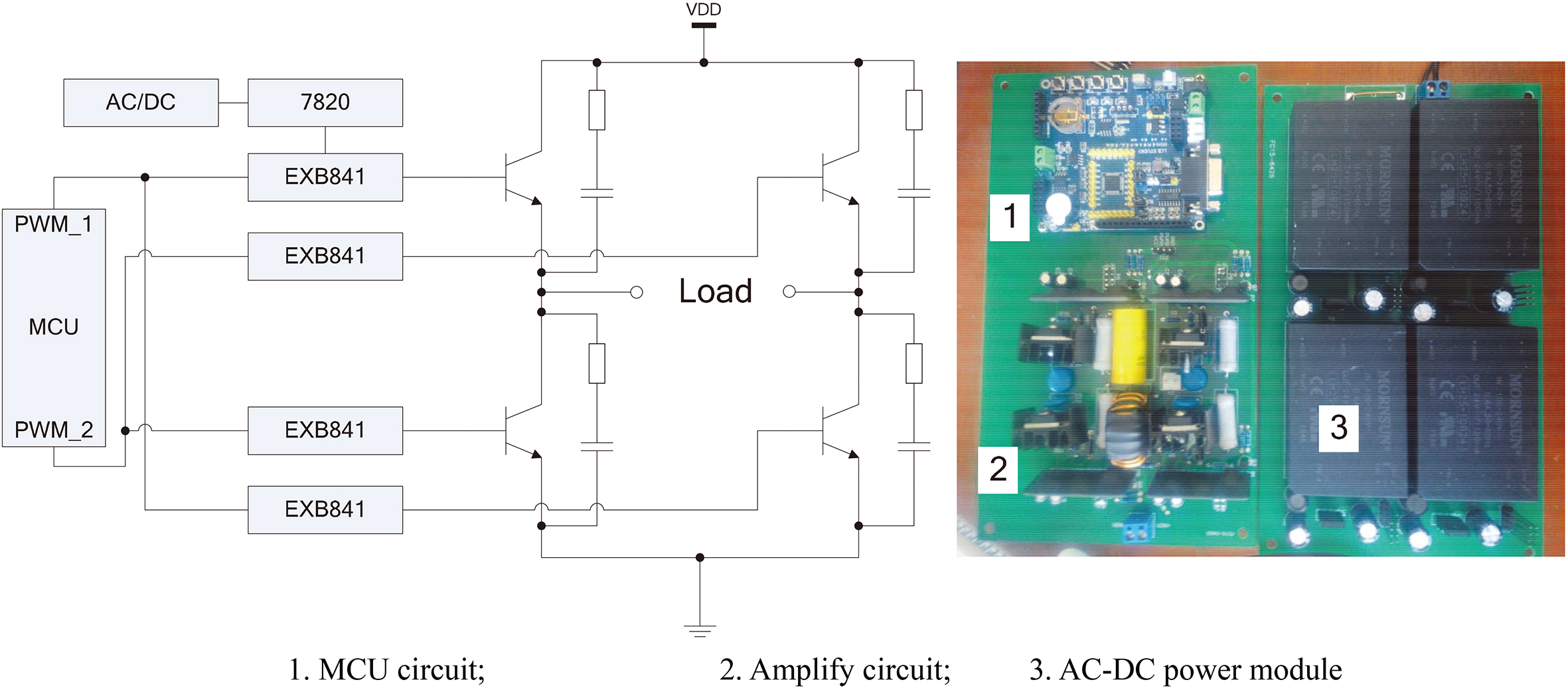
The basic structure and working principle of the power supply are elaborated as follows: the first subsystem is MCU circuit, this part works as the signal generator. We use single polar modulation method to generate a bi-direction sinusoidal signal. Single polar modulation method employs two independent PWM sources to complementary outputs. According to the Fourier expansion, this complementary method could eliminate the even order harmonics within the frequency domain we concerned. This elimination will benefit the waveform of exciting current and finally improve the spool displacement; in addition, single polar modulation is also easy to control since it doesn’t have to change the direction in each pulse; this method could also provide larger current amplitude compared with bipolar modulation since there is only one-direction pulses in each half-period. The type of MCU is STC15W4K56S4, there are 6 independent I/O ports for SPWM output which facilities us to realize the commentary output ‘PWM_1’ and ‘PWM_2’ more easily.
The amplitude of PWM signals generated by MCU is only 5 V, they are required to be amplified before driving the coil. The amplification circuit includes two stages: to begin with, the signals are amplified by four EXB841 chips, these driver chips are powered by four AC/DC power modules and enlarge the amplitude of PWMs to 15 V, which reaches the turn-on threshold of IGBT (for simplicity, there is only one AC/DC branch exhibited in Fig. 6); when IGBT is turned off, EXB841 could provide a constant
Consider the first quarter of a driving cycle, the solenoid will be charged in this initial stage, current cannot perfectly follow the wave type of applied voltage until the solenoid is saturated. In this case, the large electrical inertia of GMA coil could be equivalent as a voltage filer. Image a scenario when step voltage is applied, the coil current will track the constant voltage in a very similar curve of sine wave since most of the high order harmonics are eliminated by the equivalent filter left only the fundamental harmonic. Taking advantage of the above ‘filter effect’, the voltage in the first quarter of driving circle is hold as such a step signal.
The second quarter is considered subsequently. After the charging progress in first quarter, coil current will attenuate exponentially if the power is switched off immediately, in order to make it decay in as a sine wave, SPWM technology is employed. The pulse width
For single polar modulation, the average area of
Set
Eventually, the entire complementary output pattern under single polar modulation method is exhibited as Fig. 7.
Parameters and values in simulation
Proposed single polar H-SPWM waveform in complementary symmetry output mode.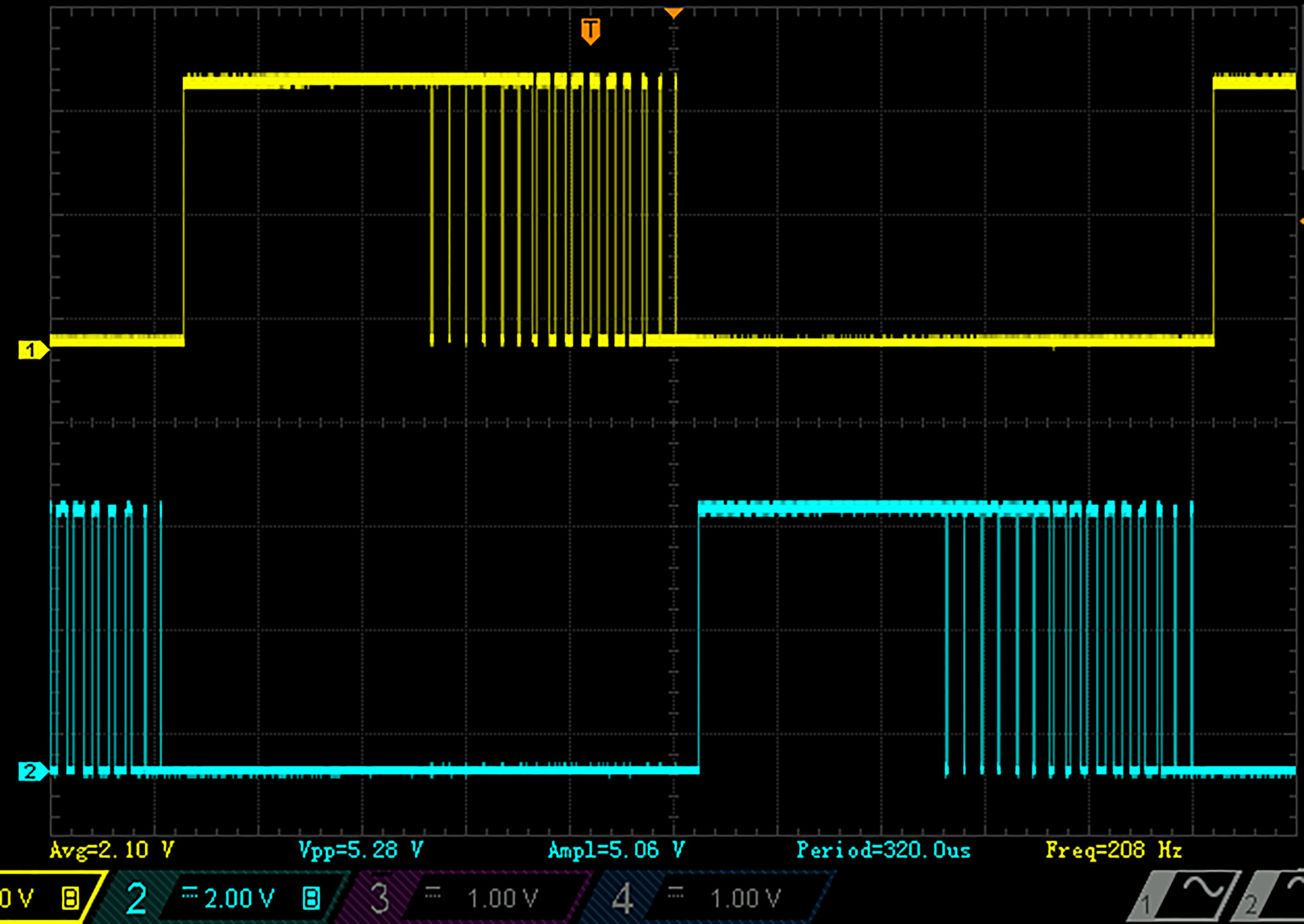
Shown as Fig. 7, the proposed driving mode uses only half of SPWM series, the modified method is therefore named as H-SPWM mode. The H-bridge of IGBT amplification circuit is excited alternatively by two ways of PWM signals. It also should be noted that there should be a certain dead zone at each direction changing spot, in order to release the considerable back electromotive force at the end of each driving circle.
Setting up for numeric simulation
In order to evaluate the performance of the proposed driving method, a numerical model is built in Simulink environment as Fig, 8a. In order to make the simulation result more practical, the H-bridge circuit is built using the SimPower toolbox as Fig. 8b. The sliding valve is formed using AMESim hydraulic simulation package as Fig. 8c and linked with Simulink as an S-Function.
Simulink model of GMA-EHSV with switching power converter.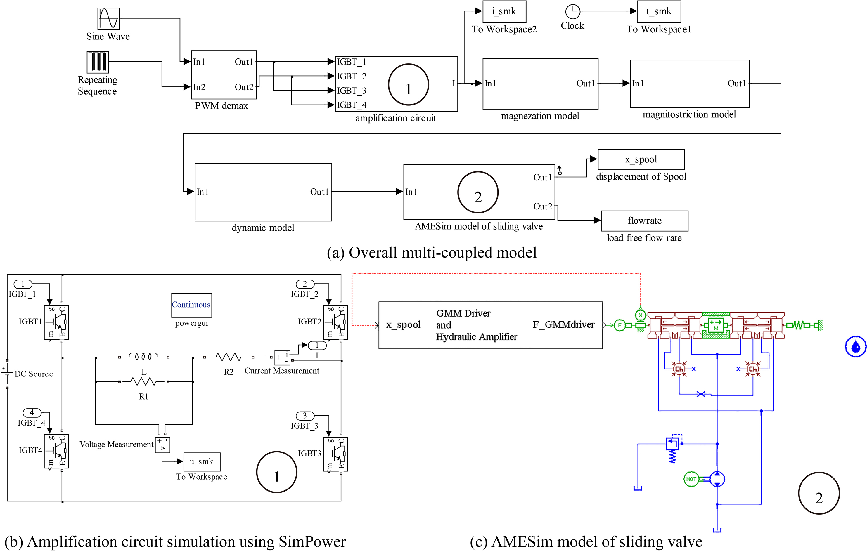
The parameters in simulation are listed as Table 2.
In order to verify the performance of our design, the simulation is conducted in both SPWM case and H-SPWM case. A series of hysteresis curves, between 50 Hz driving current and spool position are achieved under different switching numbers as Fig. 9.
Hysteresis comparisons between SPWM and H-SPWM converter.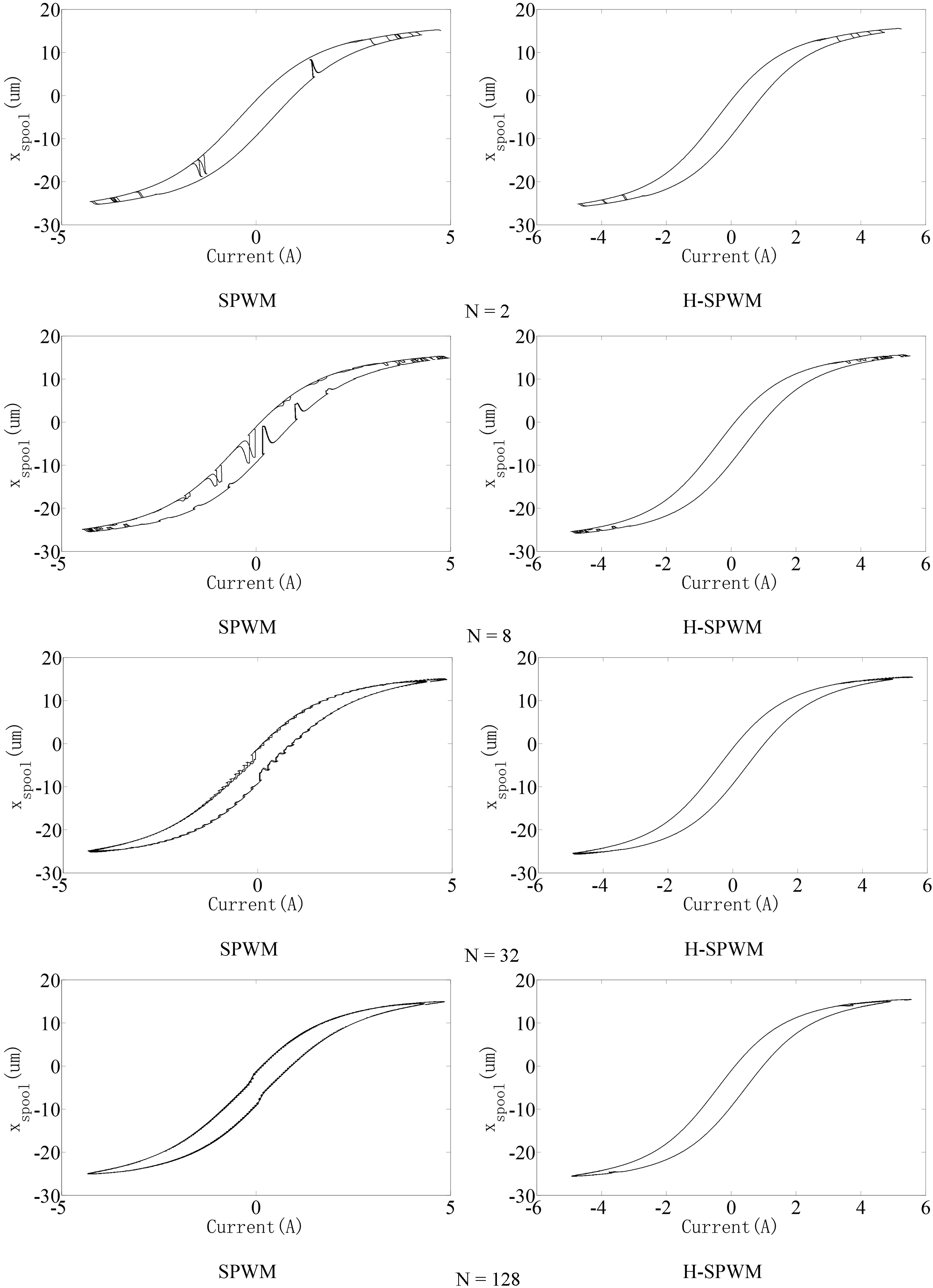
According to Fig. 9, the proposed H-SPWM converter yields to obviously more smooth curves, this is ascribed to the proposed converter takes the advantages of large inductance in GMA and reduces approximately half the switching numbers in PWM waves. Eventually, the shakes in spool position are suppressed and the smoothness is improved.
The Fourier expansion of spool position is expressed as
In which
The switching losses of the IGBT follow the laws below [21]
In which,
Comparison between H-SPWM and SPWM power supply under different pulse numbers and exciting frequencies (the transparent surface denotes SPWM driver, the opaque surface for H-SPWM driver).
Figure 10 exhibits the THD and switching losses comparison of SPWM and H-SPWM power supply. The transparent surface denotes the data of SPWM converter. In this way, the comparison of both surfaces is more distinctly.
Figure 10 indicates the proposed H-SPWM driver exhibits lower THD value and switching losses within the concerned frequency range under various pulse numbers. The average THD in proposed H-SPWM driver (0.2843) is much smaller than SPWM driver (0.3119). This is because in the proposed driver, there are fewer shakes in the current rising stages, which greatly reduces higher order harmonics; the switching losses rise in cases of more pulses and higher driving frequencies. In SPWM case, the switching losses reaches up to 83.71 W (pulse number 128, frequency 190 Hz), while in the proposed H-SPWM driver, the maximum losses is only 29.48 W. Reduced switching losses help to save energy and relieve the thermal effects of the driving system.
Displacement test and comparison with SPWM driving mode
A specific experiment is conducted to verify the performance of proposed power supply, the layout of the experiment system is exhibited as Fig. 11.
Diagram for the layout and connection of experiment system.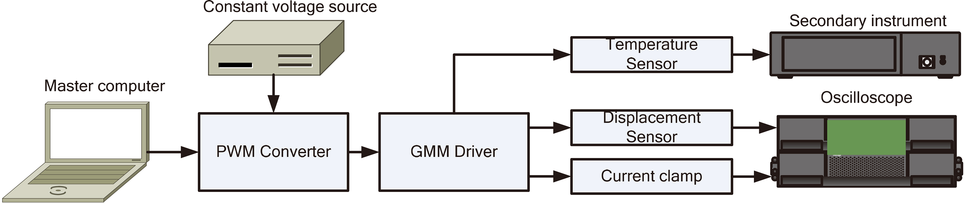
To begin with, the master computer calculates the duty circle series according to custom switching number and exciting frequency. After the series are downloaded to the MCU, the PWM converter generates the applied voltage to drive GMM driver. The displacement and current are acquired by laser displacement sensor (MTI Microtrak 3) and current clamp (Pico TA189) respectively. Both signals are exhibited in a digital oscilloscope (Rigol DS1074). During the test, the working temperature is monitored by a platinum resistance temperature sensor (WZP-CB1T3) and its corresponding secondary instrument.
In addition, as it is mentioned above, the pull-up voltage of PWM converter should be provided by a constant voltage source which could provide sufficient current for IGBT. In this test, we use a DC programmable power (ITECH IT6932A). The maximum rated voltage/current/power is 60 V/10 A/200 W. The switching number is selected as 16, which is determined by considering the hysteresis, harmonic and switching loss simulation results in above section. The practical photo for displacement test is exhibited as Fig. 12.
Photo of the displacement test system.
A series of displacement curve of GMA is obtained under different driving frequencies. When the driving frequency is lower than 100 Hz, the applied voltage is 24 V. After that, the voltage will be set as 48 V responding to the rising impedance. The oscilloscope screenshot under H-SPWM driving mode are exhibited as Fig. 13.
Displacement and current curves in different driving frequency (yellow line for displacement; blue line for current).
Given the sensitivity of laser displacement sensor and current clamp are respectively 0.25
displacement test result
Parameters for traditional power amplifier and proposed PWM converter
Learned from Fig. 13, the proposed H-SPWM converter generates a comparable smooth current curve (blue line), the displacement curve (yellow line) follows current curve effectively without considerable lag or distortion, despite some burrs in both lines induced not only by the switches of power supply but also the electrical noise of sensors.
The harmonic analysis is conducted to the test displacements of GMA under different driving frequencies. In each diagram of Fig. 13, the horizontal coordinate starts from the second order of harmonic and the vertical coordinate denotes the percentage magnitude of each harmonic compared with fundamental harmonic. The blue bars denote H-SPWM mode and red bars denote the SPWM mode. According to the diagram, the magnitude decreases with the increasing harmonic order, the decreasing rate for H-SPWM mode is faster than SPWM mode, in harmonic orders higher than five, the magnitude of H-SPWM is generally lower than SPWM mode. This is because the H-SPWM mode reduces the total switching numbers compared with SPWM method, which reduces the shakes in displacement curves and eventually suppressed high order harmonics. It should be noted the harmonic magnitude of SPWM is lower when the driving frequency is low (
In order to exhibit the performance of our proposed power supply, we employ a traditional continuous power supply for comparison. The layout for power characteristic tests is exhibited as Fig. 14.
The parameters for traditional continuous power amplifier and proposed PWM converter are exhibited as Table 4.
Unlike the proposed converter, continuous power amplifier requires an independent signal generator (RIGOL DG1022U). During the working circle, the voltage and current of both devices are measured by a power meter (EVERFINE PF210). The readings of power meter under different condition are exhibited as Table 5.
Power test result of proposed converter and continuous power amplifier
Power test result of proposed converter and continuous power amplifier
Layout for power characteristic test system.
According to the test result, the large inductance of GMA makes the imaginary part of apparent power much greater than real part. The power factor, which is derived by dividing real power with apparent power, decreases with the rising frequency. The proposed switching power supply exhibits a higher efficiency compared with continuous devices with the same driving frequency level.
Although the power consumption of both devices appears the same, the practical power consumption for continuous power amplifier is much more enormous than PWM converter since the consumption of operational amplifiers; fan and other components are not taken into consideration in the apparent power. The signal generator will also consume additional power in the overall system. On the other hand, the power consumption for the proposed PWM converter could be just regarded as the apparent power since IGBT and MCU cost only micro Amperes to maintain its function. Therefore, the proposed converter is much power saving than traditional continuous power amplifier.
In addition, the general size and weight for our converter is only 2.5% and 1% of the traditional continuous power amplifier, which makes our design more structural combinable with practical servo system.
In order to take the fully advantages of GMA in novel electro-hydraulic servo valve, we developed a specific voltage driving method, the primary innovation and major conclusions for this paper are exhibited as below:
A multi-coupled model for GMA-EHSV is proposed starting from the applied voltage, a more accurate LRR model considering parallel resistance of solenoid is proposed to cover the dynamics of exciting coil, with its parameters identified using PSO method; A switching power supply is developed based on MCU and IGBT, compared with traditional continuous power supply, this prototype could drive the transducer in a DC voltage with higher power factor, the structure is more compact and power consumption is greatly reduced; A particular modified PWM driving mode is proposed taking advantage of the large inductance of GMA, this mode realized a smoother current wave using less switching numbers and cost less switching losses.
Footnotes
Acknowledgments
The authors acknowledge the financial support from the National Science Foundation of China (Project no.51275525).