
Abstract
Eddy-current loss will cause waste of electric energy and affect service life of cable. In order to study the method of reducing eddy-current loss of cable trench in metal top pipe, a finite element simulation model was established. Firstly, influence factors of eddy-current loss were determined through a theoretical analysis, including arrangement mode of cable phase, top pipe size and cable distance. Finite element method was then used for optimal calculation of structure of cable trench and effective optimization design method was proposed. Results indicate that: for three-phase multiloop cable trench of metal top pipe, phase arrangement mode has important influence on eddy-current loss. For top pipe size, a comprehensive consideration of eddy-current loss and pipe stability should be taken in the thickness selection, and slotting position could only be at the position with maximum loss density. Both increase of distance between cable loop and top pipe and reduction of spacing between cables on the same loop will contribute to reduction of eddy-current loss of top pipe. Therefore, a cable trench structure commonly used in engineering was optimized and then its eddy-current loss was reduced by 70% effectively.
Introduction
With popularization of power cable, its defects great difficulty of cable trench construction, high cost and long construction period have been increasingly prominent. To solve these problems, a new-type cable trench has been proposed, and existing reinforced concrete (RC) top pipe is replaced by metal top pipe. Influenced by metal material characteristics and top pipe volume, eddy-current loss of new cable trench top pipe will increase by a large margin, which becomes a non-negligible part in cable transmission loss.
For single cable, its internal eddy current will cause loss and heating at metal shielding layer and armor layer and then give rise to temperature change of cable and its surroundings, and cable temperature is an important basis for reflecting its insulation state and determining its current-carrying capacity [1, 2, 3, 4]. Temperature field coupling calculation method adopted in references [5, 6, 7, 8, 9] is the mainstream method for studying current-carrying capacity. Authors of [10, 11, 12, 13] proposed that joint effects of eddy-current loss and heating of cable trench support and that of cable on the support caused rising support temperature, and it’s proposed to change distance between cable and support, cable current, cable arrangement mode and support materials to limit eddy-current loss. Authors of [14, 15, 16] proposed that eddy current in cable fittings would not only cause long-term heating of the fittings so as to result in excess local temperature of cable body and insulation aging of the cable but also would generate electromagnetic vibration stress and cause reduction of fitting strength. On the other hand, reduction of fitting thickness or enlarging middle gap between fittings can increase magnetic resistance so as to reduce eddy-current loss, but it will simultaneously degrade fitting strength and mechanical force and electrodynamic force can’t be released, so it’s necessary to determine thickness and gap width with engineering practice combined. In references [17, 18, 19], the application of high-temperature-superconductor (HTS) can effectively reduce transmission loss with low voltage and large current, current-carrying capacity is much larger than conventional cable conductor, but eddy-current loss of HTS cable mainly originates from metal top pipe. Therefore, higher critical current and lower AC loss can be obtained by designing and optimizing cable structure.
For eddy-current loss of metal top pipe in new-type cable trench, finite element method was used for simulation analysis and to study influences of structural parameters of cable trench on eddy-current loss in this paper, and then an optimization scheme was proposed by taking a cable trench commonly used in engineering and eddy-current loss of top pipe of the optimized cable trench was reduced by 70%. Cable trenches of other forms could be optimized according to the conclusions drawn in this paper, and the obtained scheme was featured by low cost and high practicability.
Calculation principle of eddy-current loss
Alternating current provided for the cable will cause alternating magnetic field, after metal material is used for top pipe, its magnetic conductivity is large, ambient electric field distribution will change, magnetic flux density of closed loop formed inside the top pipe will be far greater than ambient air, and this part of flux density will generate induced eddy current under the effect of induced electromotive force.
The eddy current generated by single-phase single-loop cable in ideal conditions in metal top pipe is as below:
Where
Loss will be caused by eddy current when flowing through the metal because of existence of resistance, and its expression is as below [10]:
Where
Accurate analytical solution of eddy-current loss of top pipe can be obtained through Eqs (1) and (2), but irregularity of actual shape and cable location should be taken into consideration in calculation of cable trench used in practical engineering with complicated model and boundary, so numerical method is used for calculation to obtain engineering numerical solution with proper accuracy. What’s used in this paper is finite element method with favorable adaptability in irregular region.
Loop positions of the cable
Cable trench structure commonly used in engineering practice (Unit: mm).
Simulation model of cable trench.
A cable trench structure commonly used in engineering practice is as shown in Fig. 1.
The top pipe of this cable trench was circular with inner diameter being 1,780 mm, a set of four-layer metal supports symmetrical at left and right were set every other 1 m, a 900 mm-width channel was reserved for constructors for going through, and support width and thickness were respectively 50 mm and 6 mm. In full consideration of magnetic conductivity and mechanical strength of the material, stainless steel was selected as material of top pipe and supports. Three-phase four-loop YJLW02 single-core cross-linked polyethylene insulated cable was set inside the cable trench and its inner core material was copper. And positions of these loops are as shown in Table 1.
ANSOFT simulation model of cable trench is as shown in Fig. 2.
As shown in Fig. 2, secondary factors like cable structure were reasonably simplified, and only 1 m cable trench was cut off for modeling analysis in the research. In analysis of eddy-current loss of cable trench, as simulation of the cable trench was featured by large field domain but small research entity, meshes under non-uniform distribution were adopted as units to implement finite element method for calculus of variations [14], and its mesh figure of Y-Z plane is as shown in Fig. 3.
Optimization design of cable trench structure
Long-term carrying current was respectively switched on in four loops as excitation, and excitation amplitudes of cables in the same loop were identical and mutual deviation of phases was 120. Specific implementation of loop excitation is as shown in Table 2.
Loop excitation
Loop excitation
Mesh figure of Y-Z plane of cable trench model.
ANSOFT Maxwell software was used to do simulation experiment, eddy-current losses of top pipe under different phase arrangements of the cables, different top pipe sizes and different distances between cables were compared, and optimization design method of cable trench structure was studied.
In consideration that eddy current induced among phases of three-phase cable would be superposed with the current of the cable itself and cause imbalance of three-phase current, so three-phase cables on the same loop should be laid as regular triangle as far as possible [20].
When there were multiple loops in the cable, phase arrangement modes of the cable were different, electromagnetic influences between magnetic fields on different loops would be different, and eddy currents generated by composite magnetic fields to the top pipe were also different.
Eddy-current losses under different phase arrangement modes
Eddy-current losses under different phase arrangement modes
Cables under triangular arrangement.
Three-phase and four-loop cable was arranged as shown in Fig. 4.
Theoretically, there should be 64 phase arrangement modes in Fig. 4. Experimental results showed that as width of middle channel was large, mutual influence of loops at left and right sides was small, for convenience of research, it’s set that phase arrangements on loops at left and right sides were symmetrical and as A, B and C phases had the feature of successive circulation being 120
Ratio definition:
Where
It could be seen from Table 3 that eddy-current loss of top pipe was greatly influenced by cable phase arrangement mode, so seeking for optimal arrangement mode was of practical value.
When cables on different loops were arranged in triangular shape, No. 12 arrangement mode in Table 3 was optimal and its phase arrangement is as seen in Fig. 5.
No. 12 arrangement mode.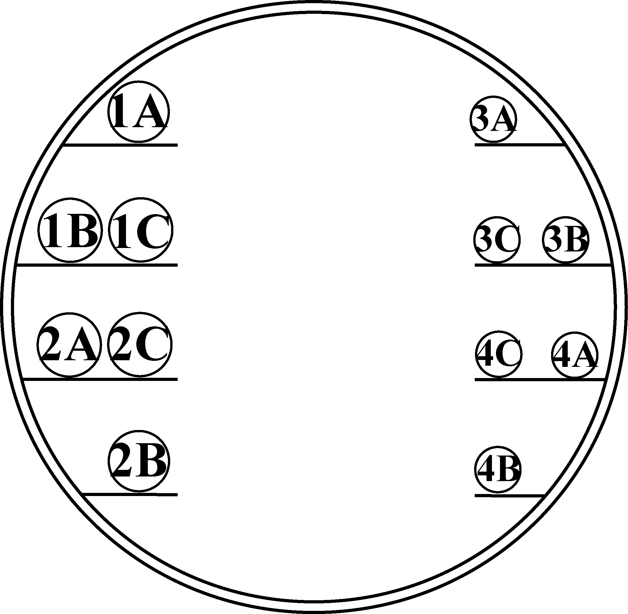
At the moment, eddy-current loss of the top pipe reached the minimum value 101.58 W/m which was only 64.87% under the worst arrangement.
Top pipe thickness
Top pipe thickness in cable trench had influence on both of its eddy current and resistance. As enough space should be reserved in the cable trench for construction and passage, during the simulation experiment, inner diameter of top pipe was fixed at 1,780 mm, top pipe thickness was changed by changing outer diameter, excitation was applied to cables on the four loops according to Table 2, finite element method was used for simulation calculation [21], and then relational curve between pipe wall thickness- Eddy-current Loss per Unit Length was obtained as shown in Fig. 6.
Pipe wall thickness – eddy-current loss per unit length.
It could be seen from Fig. 6 that relational curve between pipe wall thickness and eddy-current loss of top pipe presented reverse U shape, maximal value existed in eddy-current loss of the top pipe, and the thickness in this experiment was 20 mm or so. Theoretically, no matter pipe wall thickness was increased or decreased, the goal of reducing eddy-current loss of the top pipe could be reached, but excessively small pipe wall thickness of steel top pipe would cause instability and deformation failure of the top pipe, so proper thickness could be selected only from right half of the curve, and metal top pipe thickness suggested in this experiment was within 30
Excitation was applied to cables on the four loops according to Table 2, finite element method was used for simulation calculation, and distribution of eddy-current loss densities when top pipe was not slotted is as shown in Fig. 7. It could be seen that influenced cable location, loss distribution on the top pipe was not uniform, and loss density of red part at top left corner was the maximum being 5,500
Distribution of loss densities under non-slotting situation of top pipe.
Slotting at different positions of the top pipe would generate different influences on eddy-current loss of the top pipe and slotting positions are as seen in Fig. 8. Positions 1
Eddy-current loss values after slotting are as shown in Table 4.
Eddy-current losses at different slotting positions
Slotting positions of the top pipe.
Schematic diagram of changing distance between loop and top pipe (Unit: mm).
It could be seen from Table 4 that after slotting at positions 1
Distances between cables and top pipe
In ideal conditions, eddy current inside top pipe is unrelated to its distance from AC cable [22], but problems like cable size and armor layer should be taken into consideration in practical engineering, so the closer the top pipe is to the cable, the greater the flux density, and current will also be influenced.
As shown in Fig. 9, cables were placed in right triangular shape on the same loop, distances among three-phase cables on the same loop were kept unchanged, distance between cable loop and top pipe was changed by changing distance D, and when the distance between cable loop and top pipe increased, D would decrease. Diameter of cables used in loops 1 and 2 was
D – eddy-current loss per unit length.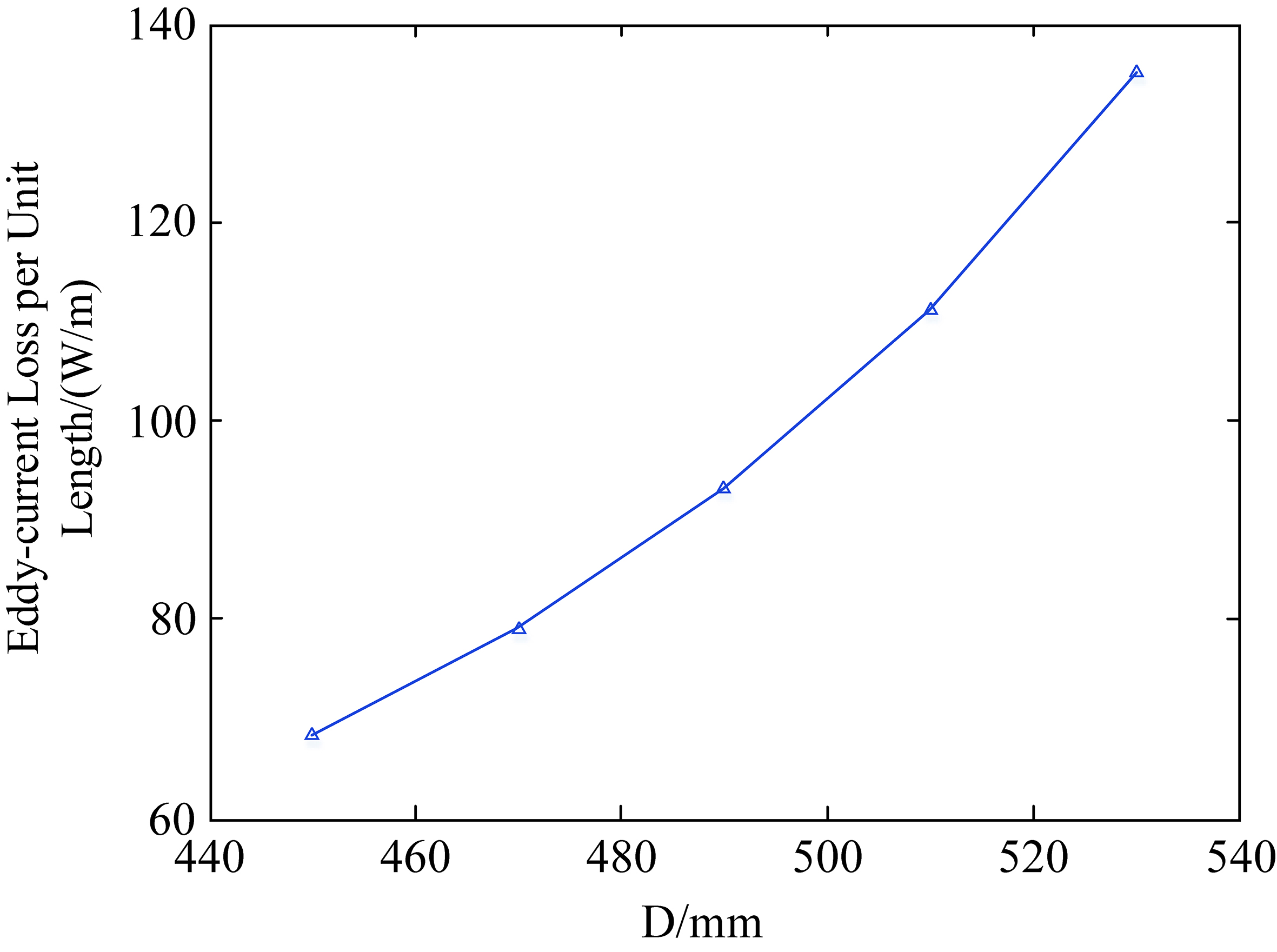
Excitation was applied to cables on the four loops according to Table 2, finite element method was used for simulation calculation, and Fig. 10 shows eddy-current losses of the top pipe under different D values obtained through simulation experiment.
It could be seen from Fig. 10 that as D increased, loss also increased more and more rapidly, so D should be as small as possible. If the width of the channel reserved for passage of constructors in the middle was considered as 900 mm, then minimum value of distance D was 450 mm.
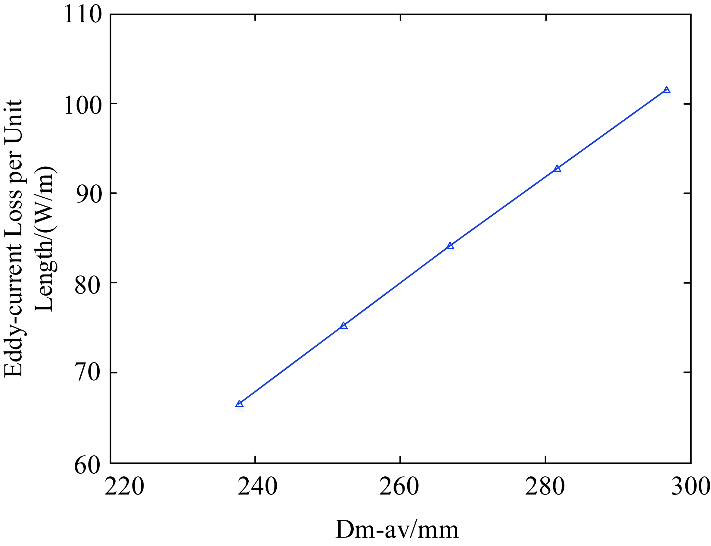
Mutual spacing between loops and distances between loops and the top pipe were kept unchanged, and average geometric mean distance
Where
Excitation was applied to cables on the four loops according to Table 2, finite element method was used for simulation calculation, and Fig. 11 is relational curve between
It could be seen from Fig. 11 that eddy-current loss of top pipe presented linear increase with
According to conclusions drawn in simulation experiment, structure of commonly used cable trench was optimized, and Fig. 12a and b are respectively phase arrangement modes of the cables before and after optimization, and other structural parameters are as seen in Table 5.
Structural parameters of cable trench before and after optimization
Structural parameters of cable trench before and after optimization
Cable trench structures before and after optimization.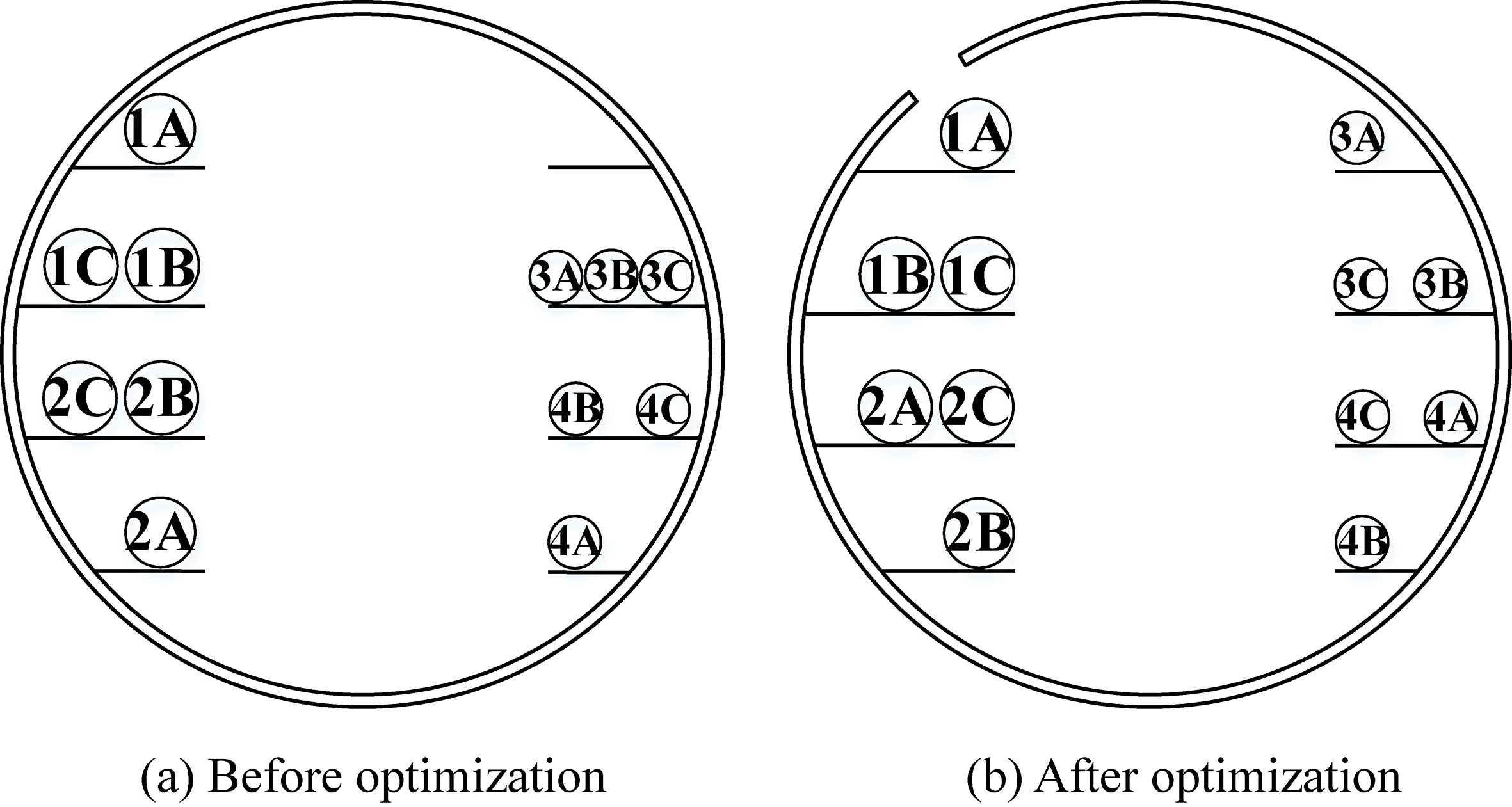
It could be seen from Table 5 that only some structural parameters of the cable trench were changed through optimization, and slotting treatment was carried out on the top pipe at proper location. When average geometric mean distance
After excitation was applied to three-phase four-loop cable according to Table 2, finite element method was used for simulation calculation, eddy-current loss of the cable trench with structure not optimized was 139.89 W/m while that of the cable trench with structure optimized was 45.61 W/m which was only 30% of that before optimization, so optimization result was ideal. Thus it could be seen that conclusions drawn in this paper were correct and effective, and cable trench structures of other forms could also be optimized according to this method.
A new-type cable trench of metal pipe top was put forward, influences of factors like phase arrangement mode of cables, top pipe size and distance between cables on eddy-current loss of metal top pipe were studied through theoretical analysis and simulation experiment and an effective optimization design method was proposed. On this basis, cable trench commonly used in engineering practice taken as an example, structural optimization was carried out and eddy-current loss of the optimized top pipe was reduced by about 70%. Compared with traditional cable trench of RC top pipe, metal top pipe, which is featured by convenient construction, low cost and high practicability, could control eddy-current loss of top pipe within a small range by optimizing cable trench structure. This research is an improvement of existing cable trenches and has provided reference for laying urban underground cables.
Footnotes
Acknowledgments
This work was supported by the National Natural Science Foundation of China (Grant No. 51677009) and Chongqing science and technology plan project (Foundation NO. cstc2017jcyjAX0181).