
Abstract
The applicability of conventional eddy current (EC) testing to detect delamination in laminates of carbon fiber reinforced polymers (CFRP) was assessed. As delamination impedes the induced currents flowing across the layers, the EC technique offers the potential for delamination in CFRPs to be detected by sensing the change in probe output signals caused by distortions in the magnetic field. In a numerical study, ECs distribution in CFRPs alters considerably in multidirectional and cross-ply laminates and currents drop steeply when delamination is present. In experiments, the detectability of delamination at different depths was investigated using 24-layer laminates, each with different stacking sequences. The change in amplitude of the probe output signal obtained from data agrees qualitatively with the numerical analysis. The size and location of the delamination defect were compared with those obtained in ultrasonic scanning images. Experiments show that delamination at a maximum depth of 0.75 mm in cross-ply samples could be detected, whereas subsurface defects in the unidirectional plate went undetected.
Introduction
Advanced carbon fiber reinforced polymer (CFRP) materials are of interest to numerous industries because of their superior mechanical properties and tailoring for complex structural applications. Laminated CFRPs, however, are particularly susceptible to low-energy impacts in engineering applications. As a result, internal damage in the form of fiber fractures, resin matrix cracks, and delamination may be induced because of poor properties in the through-thickness direction of laminates. Among the defects, delamination, which is a particular interlaminar mode of fracture and refers to the local separation of adjacent laminae, is the most critical failure mode as the strength and stiffness of the CFRPs may fall suddenly, and eventually result in unexpected failure of the CFRP structure, even when the defect is undetectable under visual inspection from the impact side. Therefore, detecting delamination is imperative in maintaining structural reliability and integrity of practical laminated CFRP structures.
The eddy current (EC) technique is a well-established nondestructive testing method for defect detection in electrically conductive materials. In accordance with Faraday’s law, under testing using a driver coil, an EC is induced in a CFRP plate because of electrically conductive fibers. Defects in CFRPs cause local changes in the EC path that result in a distorted magnetic field generating changes in the output signal of the pickup coil. Attributes such as simplicity and ease of operation, rapid noncontact scanning, online inspection and real-time imaging, and low surface-cleaning maintenance have made the EC method a quick and easy testing candidate in inspecting actual CFRP structures [1, 2]. Different types of defect including fiber breakage and cracks [3], missing or misaligned fiber bundles [1, 4, 5], fibers waviness [6, 7, 8] and impact damages [9, 10] have been detected under EC testing. However, to the best of the authors’ knowledge, little attention has been paid to detect delamination of CFRPs; there has been only a few experimental results on monitoring delamination growth caused by tension loads [11]. Controversially, another study [12] has claimed that the conventional EC-based technique lacks the requisite sensitivity to detect internal delamination in laminated CFRP composites.
Therefore, under scrutiny here is whether the conventional EC technique is capable of detecting delamination in laminated CFRP composites. First, an optimal working frequency of the EC probe is determined such that the pickup coil produces its largest fractional change in voltage. Second, the detectability of delamination defects using the method is investigated in numerical simulations and experiments. We analyze the influence of delamination on ECs induced in laminated CFRPs and also changes in amplitude of the probe’s output signal. In the experiments, different laminated CFRP samples with artificially induced delamination are tested to verify the reliability of the EC detection approach. Finally, concluding remarks are drawn.
EC probe characterization
The probe is one of the more critical parts of EC technique; its sensor provides the high sensitivity when currents are strongly altered by discontinuities caused by cracks. Coil structures are the most widely used type of sensors in EC probe for detecting the wide variety of defects. In general, the skin effect limits the effective detection depth to the near surface. The research of Reimche et al. [13] and Mook et al. [14] showed that the non-axial transmit-receive (TR) probe (Fig. 1a) offers potential enhancements in inspection depth by optimizing the distance between its two coils. Moreover, in imaging applications, the point spread function (PSF), which describes the imaging response to a point input, of the EC probe is of great interest as it plays a critical role in EC imaging. Compared with coaxial EC probes, the PSF of TR-type probes has a Mexican-hat shape when it passes through a point-like defect (Fig. 1b and c) and is more suitable for imaging. For this reason, the TR-type probe is employed in this study.
(a) Configuration of transmitter-receiver (TR) probe; (b) EC probe passing through a point-like defect; (c) PSF of coaxial and non-axial coils.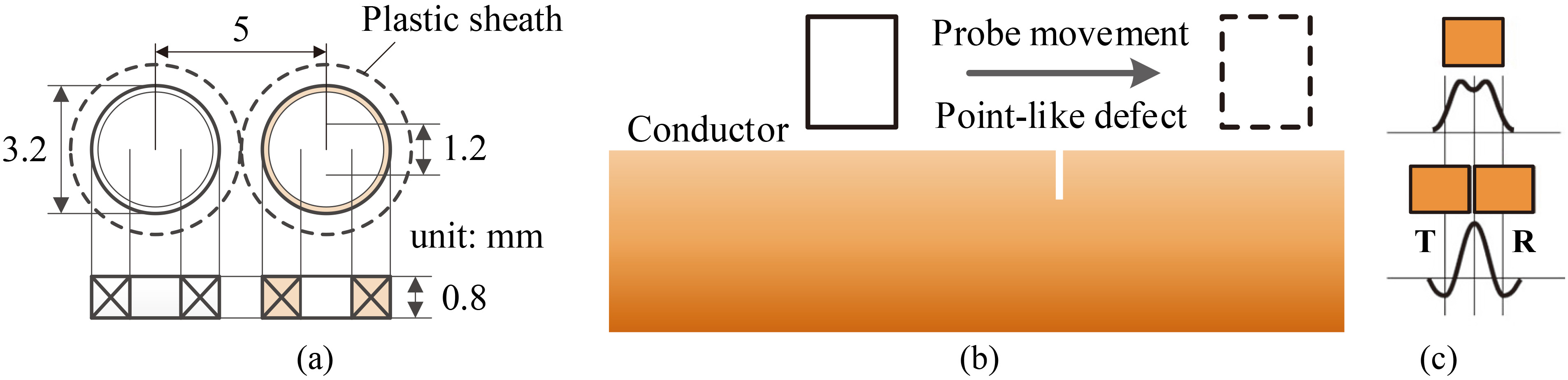
In practice, conventional EC testing operates either at a low frequency or at high frequency. However, the sensitivity of the probe output voltage at low frequency is not sufficient for CFRP testing because the electrical conductivity is low. At higher frequency, the probe is more susceptible to liftoff, tilt, and surface roughness, causing higher background noise. Thus exploring an effective alternative for maximizing the probe sensitivity is important. Reports [15, 16, 17] prove that shifting the electrical resonance frequency is potentially a complementary approach to maximize the inspection sensitivity without needing complex probe designs or data analysis.
According to circuit theory, an EC probe can be simply modeled as a singular lumped element with an effective capacitance and inductance; its inherent frequency (
where
where
Using an impedance analyzer (Agilent 4294A), an experiment was performed to investigate both the inherent and resonance frequencies (i.e.,
From the impedance-frequency curves (
Resonance frequency, signal peak frequency and voltage of the probe both off and on the undamaged conducting materials
(a) Impedance-frequency curves of the TR probe in air and above two different conductive materials; (b) Resonance-shift of the output voltage of the TR probe on CFRP (solid line) and Aluminum samples (dash line).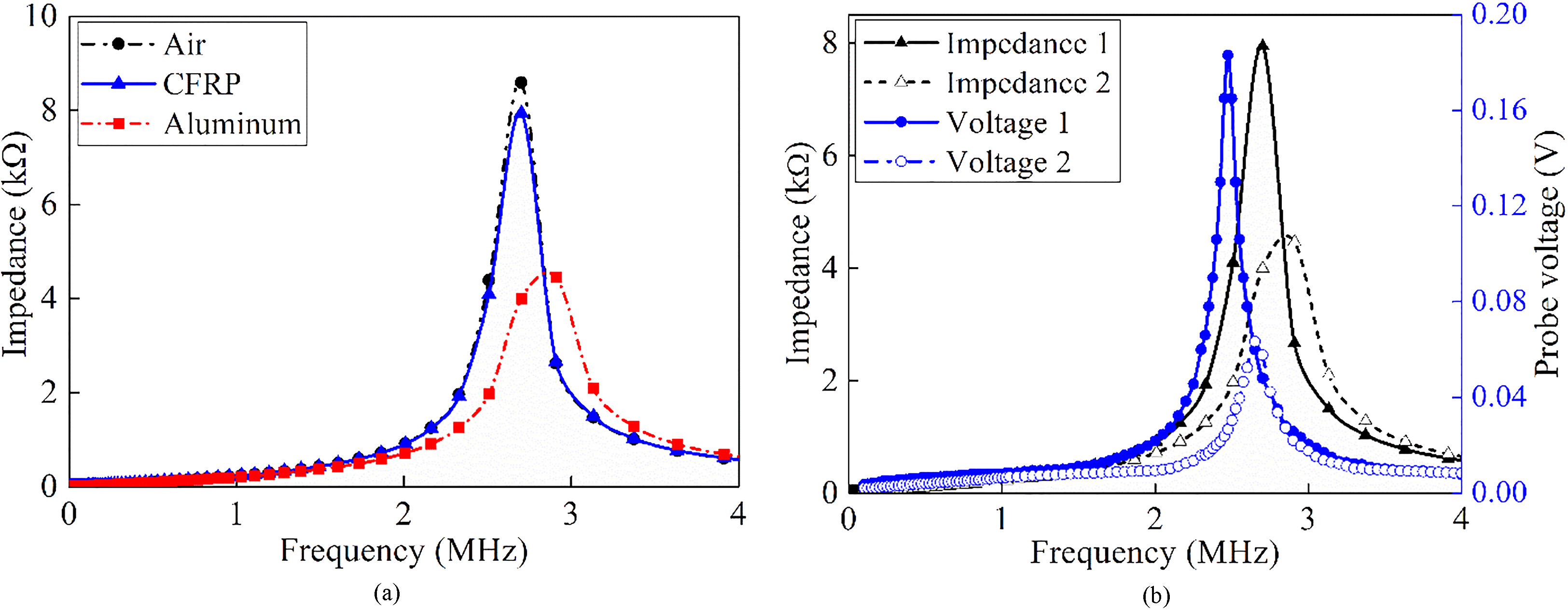
Modeling of interior delamination: (a) electric insulation element as delamination; (b) section profile of the model.
To establish the appropriate frequency that improves the detection sensitivity of the conventional industrial EC technique, a frequency sweep method is applied by driving the probe with a sinusoidal voltage
The EC-based method has been successfully used to detect defects in laminated CFRP materials. Previous studies demonstrated that ECs flow along fibers and at fiber-fiber contact points pass from one to the other. Once delamination occurs, the network of fiber contacts between adjacent laminae breaks. Breakages results in discontinued currents and ultimately affects its conductive property. To investigate the influence of delamination, finite-element (FE) numerical simulations and analyses of the electrical properties of CFRP materials are first presented and detailed below. The FE model configured COMSOL Multiphysics is presented in Fig. 3.
Numerical model
Three plate models (100 mm
Stacking sequence of samples
Stacking sequence of samples
Contact resistivity for various composites [20]
Using the magnetic vector potential
where
Generally, delamination – the separation of two adjacent lamina – is a planar defect occurring within the CFRPs. Hence, to model the delamination, an electric insulation element is inserted between the adjacent layers with the proviso that
where
Numerical results of the 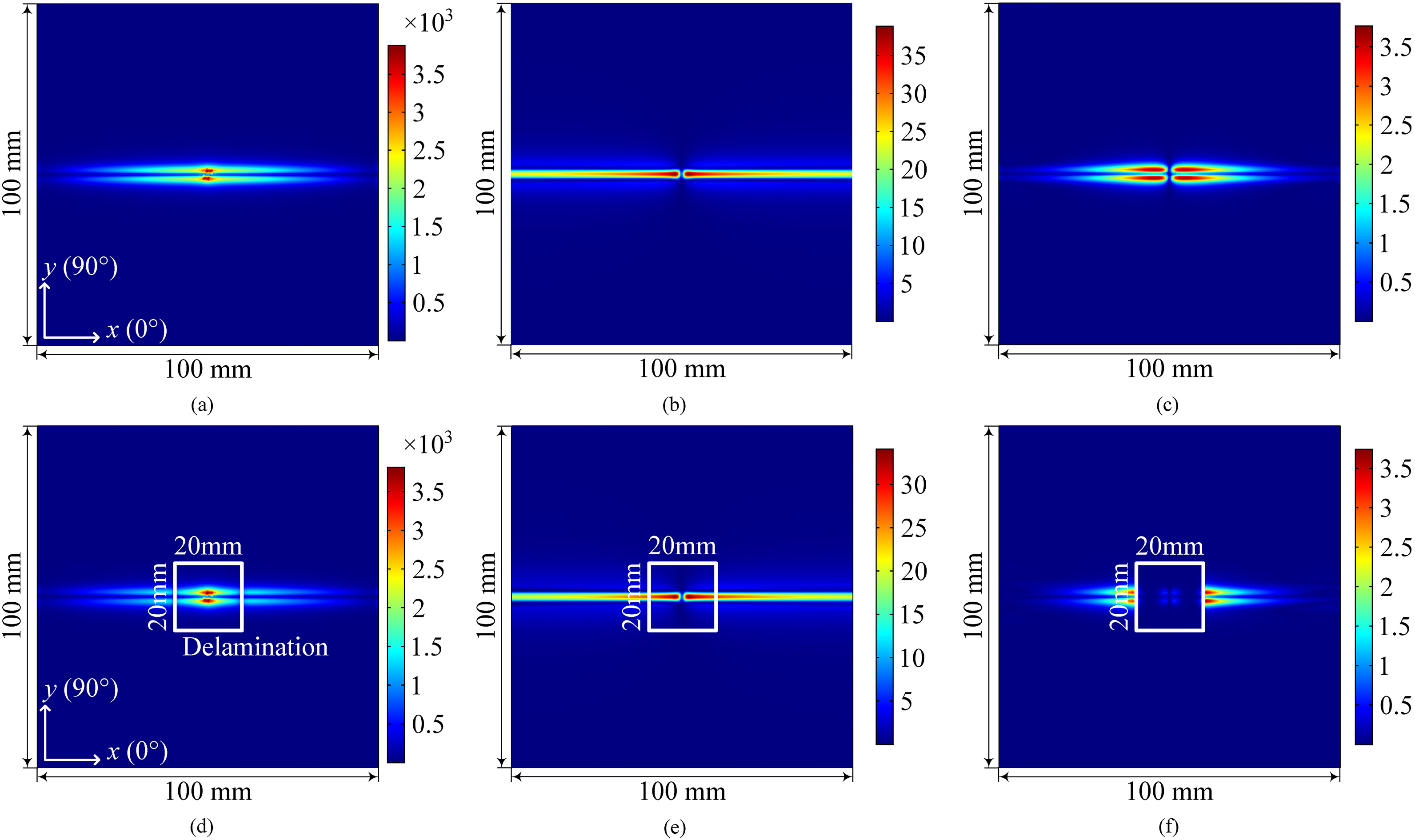
As for Fig. 4 but with sample M2.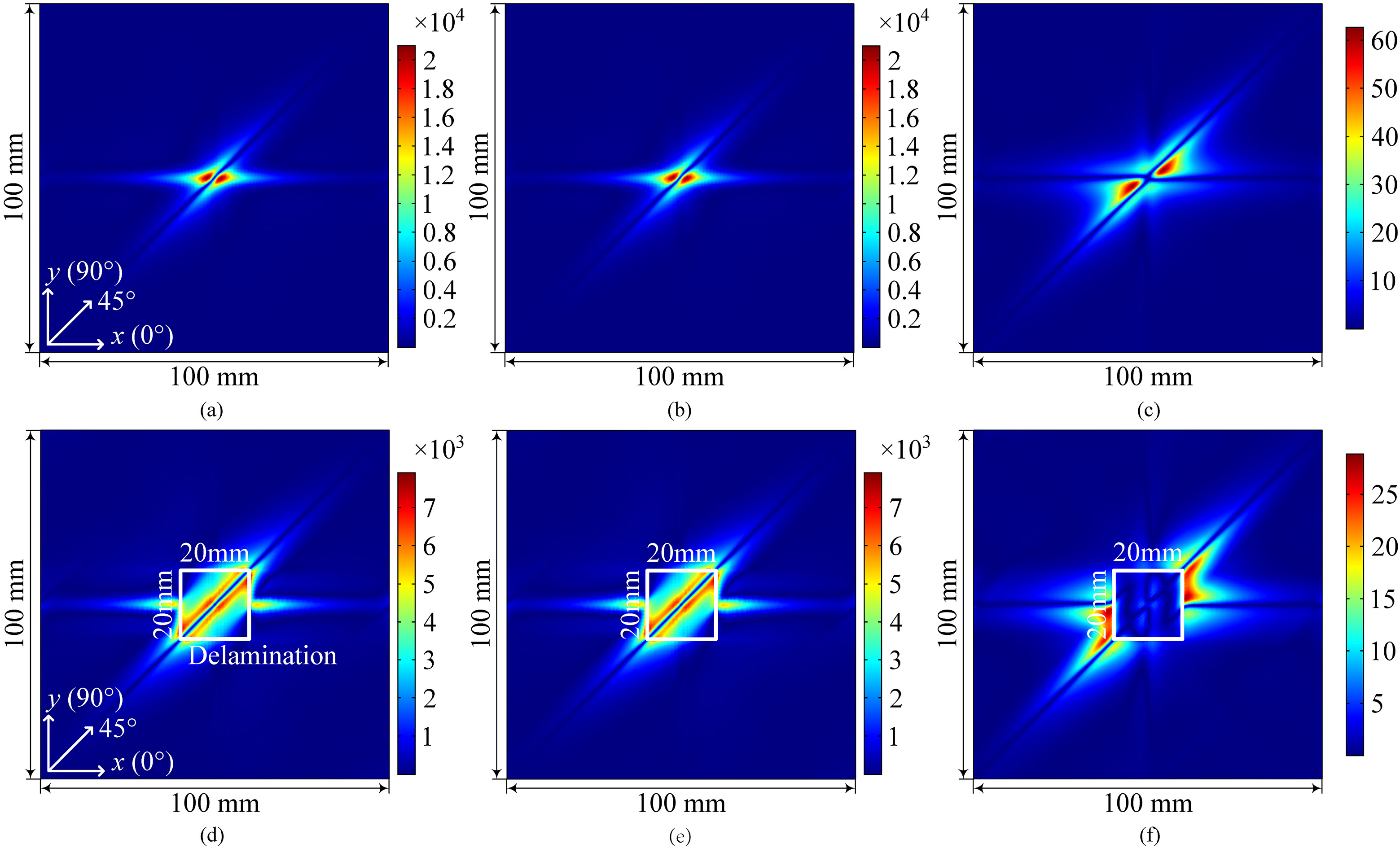
As for Fig. 4 but with sample M3.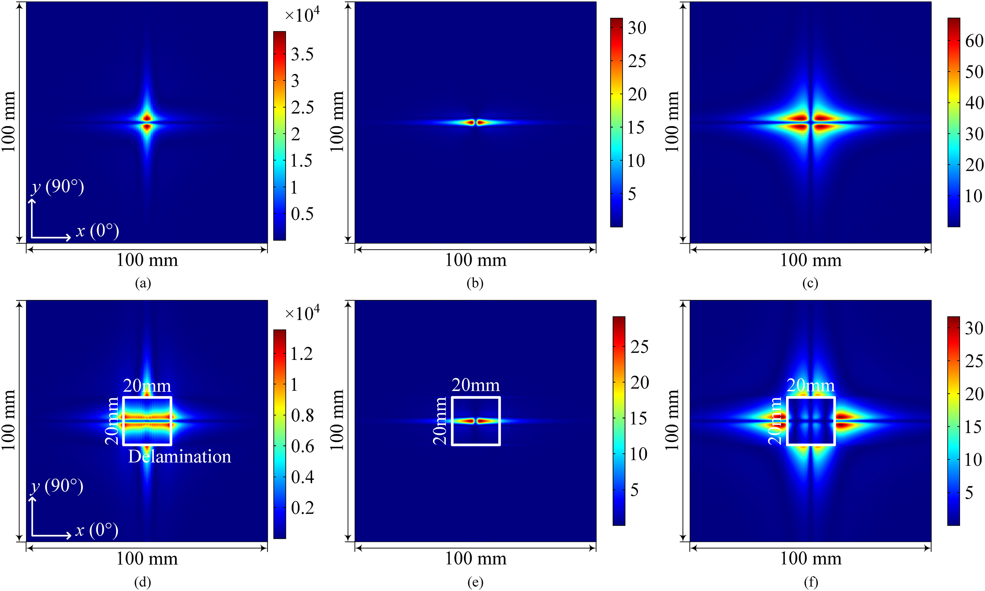
Numerical results of the EC densities obtained from plates M1–M3 are shown in Figs 4–6; the solid boxes mark the site of delamination. All current densities presented in the figures are from the 2nd interface between the 2nd and 3rd laminae. Note that the EC density distributions from the three samples are very different from each other.
The directional components of the current
Distributions of
Current repartition in the multidirectional composites M2 and M3 supports the notion that interlaminar damage has a significant influence on current densities near the interface between two laminae with different fiber directions. This is because the fibers of such laminae tend to press against each other during curing, causing a high concentration of current density around the interfaces (see Fig. 7a). In contrast, at the layer-layer interface of sample M1, fibers from one simply sank into the fibers of the other, and hence little current is found near the interface. In other words, the number of contact points between fibers at an interface is less for 0
Current density 
From the foregoing numerical analyses, delamination does influence the ECs near the interface between two different plies, causing a repartition of the current path and a steep attenuation of the current density. In-plane current density profiles in the through-thickness direction of sample M3 without and with delamination at various depths (Fig. 7) provide a quantitative comparison. Note that the induced current is found to be highly concentrated around all the interfaces of M3 regardless of delamination. However, a significant decline in current density takes place at interior delamination sites (Fig. 7b and c, marked by open ellipses). This is consistent with the fact that delamination defects are capable of impeding current flowing across the interface, resulting in a sharp decrease in current density around the delamination site.
Moreover, the current density of the 1st lamina drops from its maximum value at the top surface (Fig. 7a–c), whereas a maximum value appears at the top surfaces in all other seven laminae. Here the fiber contact through the laminae enables current to flow across the interface and combine with other currents, leading to current concentrations around the interfaces. In contrast, delamination impedes currents flowing across the interface, and therefore provides no contribution to that of subsequent laminae. Hence the amplitude of the current density around the intact interface is larger than that around the delamination site.
To describe the extent of the influence of delamination, the voltage variation of the EC probe is numerically calculated. The
where
Voltage changes obtained from samples M1–M3 of various plies with delamination at different depths.
The change in output voltage of the EC probe is plotted in Fig. 8. For the unidirectional plate M1, the output voltages obviously remain almost unchanged, whereas a significant voltage change is found when delamination occurs in multidirectional laminate M2 and cross-ply one M3. From the analysis above, current concentrations occur around the intact interfaces of the two laminates but attenuate steeply at delamination sites, resulting in a significant reduction in output voltage amplitudes. However, the influence of delamination on the ECs in the unidirectional sample is negligible, and hence a slight output voltage is obtained. The change in output voltage therefore reveals the delamination influences affecting the ECs when fiber directions on the opposing sides of the interface are different. Furthermore, the larger the angular difference is between adjacent laminae, the greater are the current density and the voltage change near the interface. Also, a shallower delamination depth produces stronger current density attenuations and larger voltage changes.
Experiments were conducted to detect and evaluate artificially induced delamination damage in CFRP laminated materials of different plies. Meanwhile, size and location of the delamination were compared with those imaged by an acoustic emission device (C-scan, Physical Acoustics Corp. (PAC)) using a scanning frequency of 5 MHz.
Parameters of fabricated CFRP samples
Parameters of fabricated CFRP samples
Schematic showing the fabrication of a laminate with artificial delamination.
(a) Photo of the EC experimental setup; (b) Schematic of the experimental setup.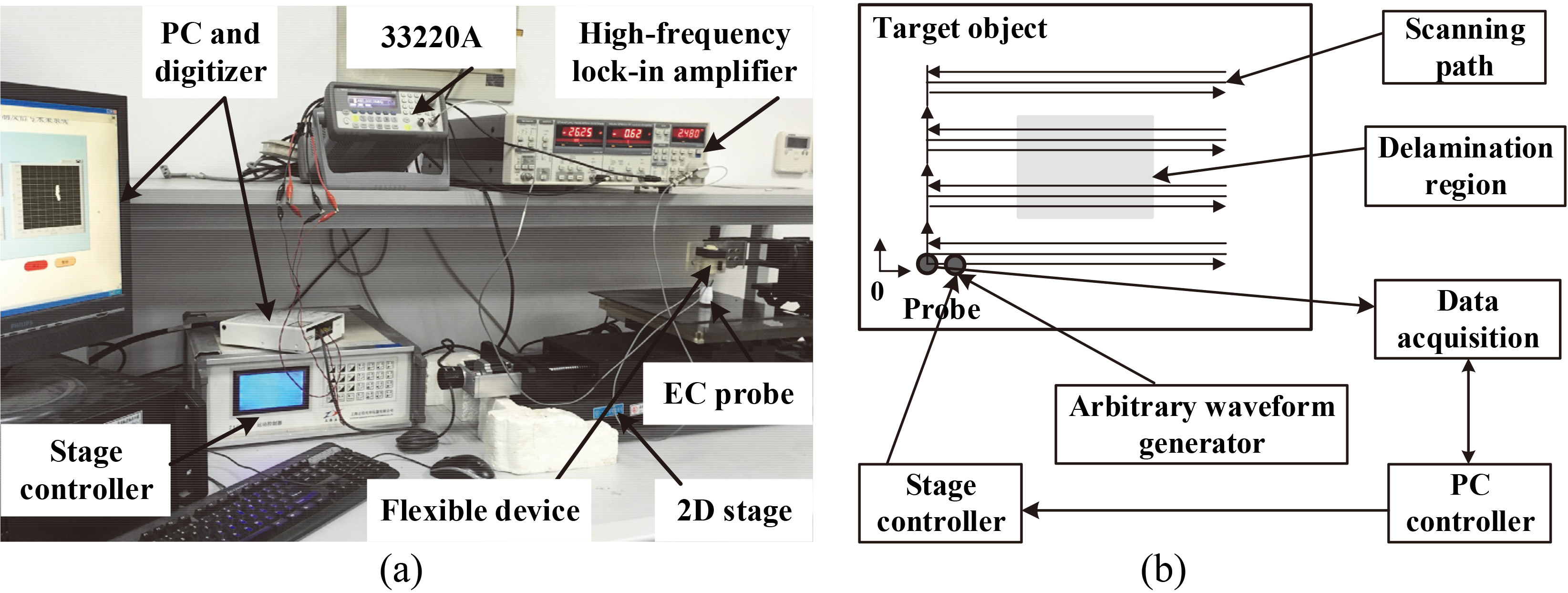
Voltage signals obtained from the different CFRPs with and without inside delamination.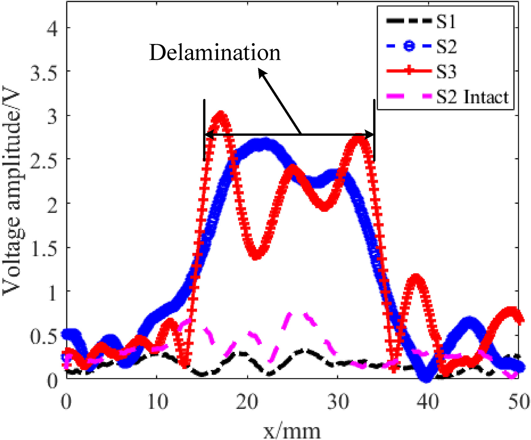
(a) Eddy current scanning image of sample S1; (b) Ultrasonic C-scanning image of sample S1.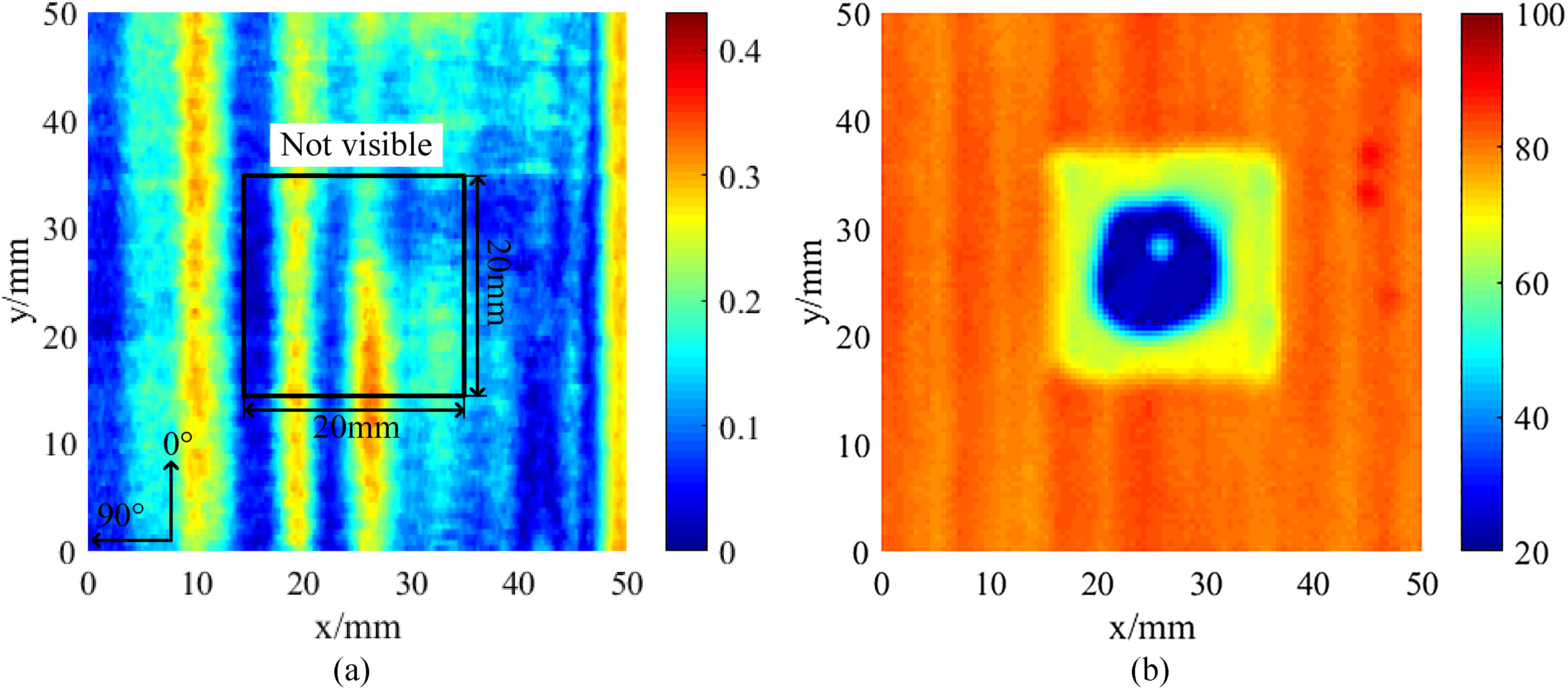
As for Fig. 12 but with sample S2.
As for Fig. 12 but with sample S3.
Eddy current scanning images of (a) sample S4, (b) sample S5 when spacing 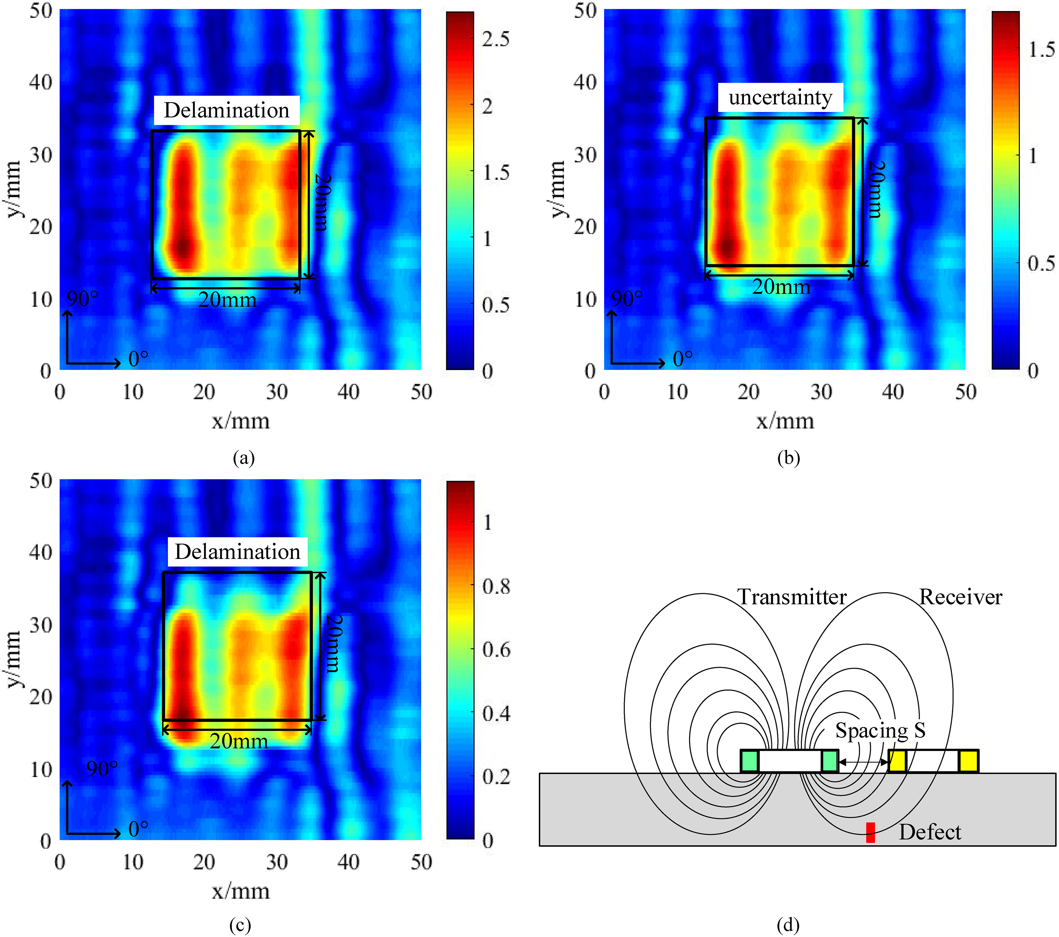
Five hand-made samples, marked as S1–S5 (Table 4) were fabricated by laminating 24-layer tailored unidirectional prepregs in different directions 0
ECT system
The EC-based testing system for scanning and imaging of CFRP materials was developed in the authors’ laboratory (Fig. 10). In the system, a TR-type probe (see Section 2, Fig. 1a) is fixed to a flexible supporting bar for inducing and sensing ECs; the driving frequency is the obtained frequency
Even if the EC probe operates at frequencies close to resonance, the obtained voltage signal is still small (Table 1). To extract the useful weak signal, the lock-in amplifier is used as the processing unit, enabling signal measurements to be taken with high precision and inspections of the small defects.
Results and discussion
Figure 11 shows the profiles of the output voltage signal of EC probe obtained from different samples with and without inserted delamination. The voltage signals are quite distinct. A significant voltage variation can be observed from both samples S2 and S3 in the simulated delamination zone, whereas a very small variation is observed between sample S1 with a delamination defect and S2 without delamination. For the unidirectional sample S1, delamination produces little influence on ECs around the interface because fibers are aligned (Fig. 4a–f), and thus the obtained change in voltage by the probe is almost zero. The experimentally obtained nonzero voltage is due to some inevitable experimental uncertainties, for example, from the periodic fiber structures, the fabrication of the test sample, liftoff, and tilt of the probe. According to the heterogeneous properties of the CFRP materials, the periodic fluctuation signal is a response from the periodic fibers structure, which is caused by fluctuations in conductivity of the carbon fibers and resin matrix.
Figures 12–15 show the images of the artificial delamination defect in the different laminated CFRP samples using the EC approach and ultrasonic C-scan experiments; the plots give the voltage signal recorded at each scanning point. The scanning distances are in the plane of the laminate (Fig. 3, the
Experimental images obtained from the multidirectional and cross-ply laminates (Figs 13 and 14) at depth 0.25 mm clearly show the defects (marked by open squares). The actual size and location of all defects are accurately reflected in the images and are in good agreement with those in the C-scan images. The conventional EC approach, therefore, looks promising in the detection of delamination defects in multidirectional and cross-ply laminates, in which fiber directions of adjacent laminae are different. This is because delamination results in a distortion of the EC distribution near the interfaces between the two laminae (see Figs 5a–f and 6a–f).
From the experimental images of samples S4 and S5 obtained using the EC method (Fig. 15a–c), changes in the output signals become smaller with increasing delamination depth. The delamination defect at 0.5 mm depth in sample S4 is distinguishable (Fig. 15a) but not clearly identifiable in sample S5 (Fig. 15b) when the spacing (
Hence, we concluded that the practicability of the conventional EC technique in detecting subsurface delamination defects is promising, and the inspection sensitivity is found to depend on fiber directions on the opposing sides of the interface.
Conclusion
The detection of delamination in laminated CFRP composites were investigated from numerical modeling and experiments using conventional EC testing. Characterization of the EC probe was done through a frequency sweep method for improving the detection sensitivity. Eddy current distributions in CFRP laminates with delamination defects was investigated using FE analyses. Fiber orientation on both sides of the delamination interface was found to have significant influence on the ECs and thus affected inspection sensitivity. For adjacent laminae with different fibers orientations, the current density distribution is altered in the delamination site undergoing a steep drop that causes changes in the output voltage of the pickup coil. For adjacent laminae with the same fiber orientation, however, the current density distribution is almost unaltered in the delamination site, resulting in little or no change in output voltage signal.
Finally, delamination detectability at different depths was investigated in experiments using a 24-layer laminate with different stacking sequences. The amplitude variations of the probe output signal obtained were qualitatively in agreement with numerical analyses. Size and location of the delamination defect were compared with those obtained from ultrasonic scanning images. The experiments showed that the subsurface delamination with a maximum depth of 0.75 mm in cross-ply CFRP could be detected by increasing the spacing between the two coils but subsurface defects in unidirectional plates were undetectable.
Footnotes
Acknowledgments
This work was supported by Key Project of National Natural Science Foundation of Jiangsu Province (No. BK20150061), the Fundamental Research Funds of the Central Universities (No. NE2015001), the Research Fund of State Key Laboratory of Mechanics and Control of Mechanical Structures (Nos. MCMS-0517K04 & MCMS-0517G01), the Priority Academic Program Development of Jiangsu Higher Education Institutions (PAPD). In addition, this work was also partly supported by the JSPS Core-to-Core Program, A. Advanced Research Networks, and “International research core on smart layered materials and structures for energy saving”.