
Abstract
When applied in the field of sealing liquids, sealing performance of ferrofluids degrades due to the surface instability induced by direct contact and relative motion between ferrofluids and the sealed liquids. Consequently, it can not be widely applied. In order to improve the performance of ferrofluid seal for liquid medium, an improved ferrofluid seal adding gas isolation device was developed to prevent direct contact between ferrofluids and the sealed liquids. The critical pressure of the improved ferrofluid seal was derived theoretically. Magnetic field intensity in the seal gap and fluid dynamics of the sealed liquids and compressed gas were simulated. A special designed experiment platform was built on which the critical pressure and seal life of the original structure and improved structure were measured and compared. From the theory and experiment results, it can be seen that sealing performance has been significantly improved with the adoption of the improved ferrofluid seal and the sealing problem has been solved by converting sealing liquids to sealing gas. The results of this study give a guidance for solution of sealing liquids with ferrofluids.
Introduction
Ferrofluid seal is non-contact liquid seal with a series features such as zero leakage, low friction, long life and high reliability, which has been successfully applied in gas and vacuum sealing [1, 2]. However, when applied to seal liquid medium, direct contact and relative motions of ferrofluids and the sealed liquids lead to surface instability phenomenon [3, 4, 5]. With the increase of linear speed and sealing pressure, the surface instability intensifies, thus the sealing performance gets worse and limits the application field.
In order to enhance the sealing performance of ferrofluids in liquid environment, long-term researches have been made by scholars from many countries. Among them, the representative works were mentioned as follows. Rosensweig firstly studied the interface instability between ferrofluids and other liquids in the influence of magnetic field [6]. Williams and Malsky researched the performance of diester based ferrofluids in sealing air, water and fluorocarbon liquid coolant [7]. The experiment results demonstrated that ferrofluid seal displayed the same performance in sealing liquid or gas medium under low rotational speed. Kurfess and Muller studied the influence of rotational speed, temperature and magnetic field strength on the seal life of different ferrofluid seal structures, but the seal life was relatively short for all the structures [8]. Szczech and Horak concluded that for non-static seals in water environments a slight and continuous loss of tightness could be observed which was caused by the peripheral speed of the seal, water pressure and certain properties of the ferrofluid [9]. Mitamura et al. made a research on the long-term ferrofluid seal applied in blood pump and the seal life was enhanced significantly by using a shield on the pole shoes, which was measured as 286 days [10, 11, 12]. However, the ferrofluid seal was run at a relatively low linear speed, about 0.9–1 m/s. Szydlo made sealing experiments with ferrofluids and water contacted directly and the results showed that ferrofluids could be effectively used in sealing water within an extremely low speed range [13, 14]. Matuszewski concluded that rotary ferrofluid seal could be applied in water in a lower velocity [15, 16]. From the indication of the above studies, the ferrofluid seal is not capable for sealing the liquid medium at a relative higher speed at present and no effective solutions can be found in existing literatures.
Therefore, in this paper an improved ferrofluid seal adding gas isolation device was developed to fundamentally overcome the surface instability caused by the direct contact of ferrofluids and the sealed liquids, thus enhances sealing performance of ferrofluids for liquid medium.
The improved structure of ferrofluid seal. 1. liquid chamber; 2. liquid isolation ring; 3. ferrofluids; 4. permanent magnet; 5. pole pieces; 6. shaft; 7. bearings; 8. shell; 9. gas-liquid isolation ring; 10. gas vent; 11. breathing ring.
Improved method in sealing liquids with ferrofluid seal
The original ferrofluid seal, as shown in Fig. 1a, consisted of a non-magnetic shell, magnetically permeable shaft, annular permanent magnet and a pair of magnetically permeable pole pieces. These pole pieces each extended from one end of the permanent magnet to a close, non-contacting relationship with the exterior surface of the shaft, thereby forming a small gap, in which ferrofluids were disposed and retained in the shape of a “fluid O-ring”. Magnetic flux path passed from the poles of the magnet and through the shaft and pole pieces, thereby forming a hermetic seal. In this structure, “O-ring” sealing rubber was used between the pole pieces and the shell. The uniform gap between stationary pole pieces and the shaft were located using the bearings. A plurality of teeth was set into the surface of the shaft surface, thereby forming a multiple-stage seal.
In the original structure, ferrofluids directly contacted with the sealed liquids so the sealing performance was poor. In the improved structure gas isolation device was added. The ferrofluids and the sealed liquids were separated by gas isolation device. The sealing problem has been solved by converting sealing liquids to sealing gas.
As shown in Fig. 1b, the improved structure of ferrofluid seal added two parts, the gas vent and the breathing ring. The space between ferrofluids and the sealed liquids was connected to compressed gas through the gas vent. The pressure of compressed gas was less than the critical pressure at the end of the ferrofluid seal and equal to the pressure at the end of the sealed liquids. There was surface tension present on the interface of compressed gas and the sealed liquids [17]. When the gap between the outer shell and the rotating shaft was small, a stable air bubble could be formed at the upper end of the gap to block the sealed liquids. Furthermore, the direct contact between the ferrofluids and the sealed liquids was avoided. The inner structure of the improved sealing structure excluding the outer shell and the liquid chamber was shown in Fig. 2.
The inner structure of the improved seal structure. 1. shaft; 2. bearing; 3. pole pieces; 4. permanent magnet; 5. breathing ring; 6. gas-liquid isolation ring.
Permanent magnet was made from NdFeB with better magnetic characteristics and less specific gravity; Pole pieces and shaft were made from magneto conductive stainless steel 2Cr13 with good corrosion resistance. Owing to the diameter of the shaft is 12 mm, the rectangular pole teeth were set on the shaft to facilitate processing. Ferrofluids were in the gap of pole teeth and the shaft.
Engine oil based ferrofluids were prepared in the experiment. The Fe
The magnetization curve of the ferrofluids.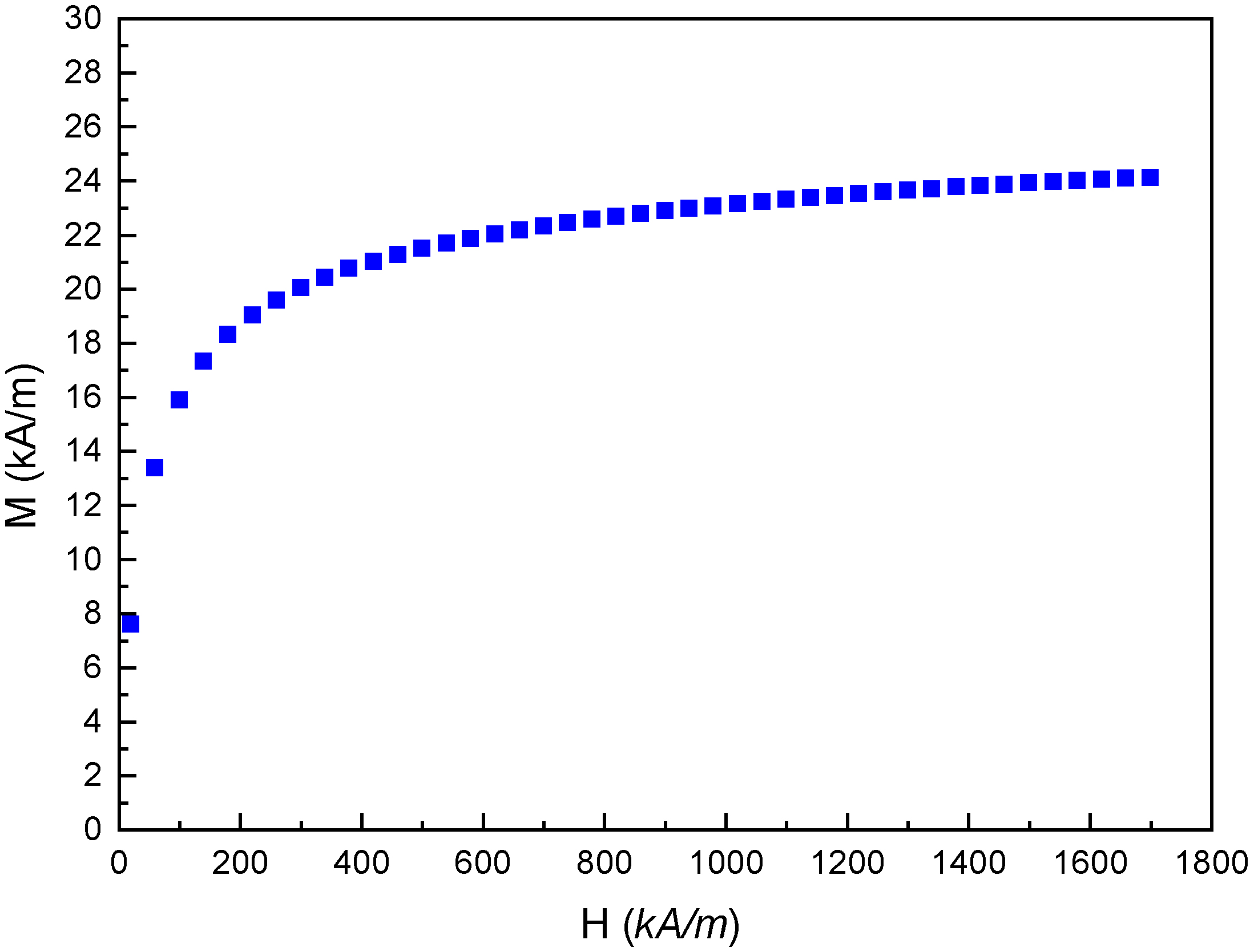
Theoretical deduction of critical pressure of the improved structure
It is supposed that the pressure on the lower surface of the interface of the compressed gas and the sealed liquids is
Pressure at the interface of compressed gas and the sealed liquids.
For the point on the lower surface of the interface,
Where
For the point on the upper surface of the interface, the Eq. (2) is known by the Bernoulli equation:
Where
From Eqs (1) and (2), we can obtain:
Where
The pressure difference caused by the surface tension and the pressure caused by the sealed liquids are very small compared with the critical pressure of the ferrofluid seal, so they can be neglected. That is, the pressure of the compressed gas in the improved seal structure is equal to the pressure at the sealed liquid end, the critical pressure of the improved structure sealing liquid medium is equal to the critical pressure of the ferrofluid seal sealing gas medium.
From Bernoulli’s equation of ferrofluids and corresponding assumptions, the critical pressure formula of the single-stage ferrofluid seal is obtained [6]:
Where
Assuming that the number of pole teeth is
The critical pressure of the improved ferrofluid seal structure for sealing liquids can be calculated by using Eq. (6).
Rosensweig proposes a criterion for instability of the interface between ferrofluids and the other liquids in the magnetic Kelvin-Helmholtz problem with the model as following [6]:
where fluid 1 is a nonmagnetic fluid and fluid 2 is a ferrofluid;
When the shaft rotating, the velocity gradients of the two liquids are different, thus leading to the gradual removal of the ferrofluid owing to the friction. The quantity of ferrofluids keeps reducing and reaches a critical value that the magnetic force in ferrofluids could not resist the load pressure, water goes through the ferrofluid seal stages and leads to the failure of the seal.
The simulation of the improved ferrofluid seal model was divided into two parts: upper part and lower part. The lower part was about ferrofluid seal and compressed gas; The upper part was about compressed gas and the sealed liquids. The lower part was the simulation of magnetic field intensity in the seal gap which could be used to calculate the theoretical critical pressure of ferrofluid seal against the compressed gas. The upper part was the computational fluid dynamics (CFD) simulation of the sealed liquids and compressed gas which could be used to analyze the isolation effect of the compressed gas on the sealed liquids.
Magnetic field simulation
In order to calculate the theoretical critical pressure of the ferrofluid seal for compressed gas, the magnetic field intensity in the seal gap was required which could be obtained by simulation. The finite element model was established as Fig. 5 using Ansys Electromagnetic. The displacement of all the nodes of the model was constrained and fixed. To obtain a higher accuracy, the mesh near the pole teeth were refined during the simulation. The type of the unit adopted was Plane53 (as shown in Fig. 5).
The finite element model. 1. air; 2. shaft; 3. permanent magnet; 4. pole pieces.
In order to study the isolation effect of the compressed gas on the sealed liquids, the improved ferrofluid seal was modeled to simulate the state of the interface of the sealed liquids and compressed gas. As shown in Fig. 6, The lower end of the model was the inlet of compressed gas and compressed gas could go out from the higher end of the model if the pressure of compressed gas was greater than the pressure of the higher end of the model. The gap between the shaft and the outer shell was 0.1 mm. Water was selected as the sealed liquids. The CFD simulation came in two steps. In the first step, compressed gas passed through the inlet and the bubble formed gradually; in the second step, after the bubble appearing on the interface, the inlet was closed and the bubble state was simulated.
CFD model.
CFD simulation was conducted using Ansys Fluent 15.0. Multiphase-Volume of Fluid and Viscous-Laminar models were applied in the simulation. The calculations were performed up to 1.0 ms with a time step of 0.001 ms. The materials were water and air respectively. The red color indicated that the volume fraction of compressed gas in two-phase flow was 1 and the blue color indicated that the volume fraction of water in two-phase flow was 1. In the first step, boundary conditions were as follows. The shaft rotated at 6000 rpm (circumferential speed
Construction of experiment platform
The improved ferrofluid seal structure was processed. The experiment platform was set up by connecting seal structure with the motor, the frequency converter, the pressure sensor and the nitrogen bottle, as shown in Fig. 7.
The experiment platform of the improved ferrofluid seal. 1. nitrogen bottle; 2. one-way valve; 3. pressure sensor A; 4. shell; 5. draft tube; 6. frequency converter; 7. bracket; 8. motor; 9. pressure sensor B; 10. datum collector; 11. computer.
Compressed gas was passed into the seal structure via the gas vent. The adjustable one-way valves were generally closed. If the pressure needed to be released, it could be realized by adjusting the spring preload of the one-way valve. A hole was arranged on outer shell at the same horizontal position with the gas vent and a draft tube was arranged from which the downward flow of the sealed liquids could be observed. If the sealed liquids flowed down and contacted with ferrofluids, the sealed liquids could be seen in the draft tube.
Water was selected as the sealed medium in the experiments. Engine oil based ferrofluids were injected in the seal gap. The seal gap for the experiments was 0.1 mm. Critical pressure experiments and seal life experiments of the original seal structure and the improved seal structure were carried out respectively. The difference between the experiment methods of the original seal structure and those of the improved seal structure was that: In the experiment of the original seal structure, gas isolation device did not work, the gas vent being locked. On the contrary, In the experiment of the improved seal structure, gas isolation device was used to prevent direct contact of ferrofluids and the sealed liquids.
2.5.2.1. Seal experiments of the original structure
In the experiments, the vent of compressed gas in the seal structure was blocked. Ferrofluids contacted with the sealed liquids directly. Increase the pressure of liquid chamber by charging gas from the top of liquid chamber, and install pressure sensor here.
In the critical pressure experiments, water was injected into liquid chamber till its volume was half before starting the motor. The motor was regulated by the frequency converter to accelerate rotation speed of the shaft evenly. When it reached a certain speed, the pressure of liquid chamber was slowly increased. The pressure value in the sealing chamber was detected by the pressure sensor. When the ferrofluids leaked, the pressure value was the critical pressure at that speed. The critical pressure experiments of the original structure at different rotation speeds were all carried out with the method above.
In the seal life experiments, ferrofluid seal components were reassembled. A certain pressure less than the failure pressure was applied in the sealing chamber and the rotating shaft reached a certain speed. The shaft was rotating at a fixed speed until the seal was failure. Then the seal life was recorded. The seal life experiments were carried out at different shaft speeds respectively.
The LabVIEW experimental platform: 1. PC; 2. electromagnetic valve; 3. DC power supply; 4. data acquisition device; 5. power amplifier circuit; 6. pressure sensor.
2.5.2.2. Seal experiments of improved seal structure of ferrofluids
On the improved seal experiment platform shown in Fig. 7, critical pressure experiments and seal life experiments were carried out.
At the beginning of the critical pressure experiments, there was nothing in liquid chamber and the top was unlocked. While the shaft was rotating at a certain speed, the compressed gas valve was open and compressed gas went into seal chamber from the gas vent and out of the top of liquid chamber. Water was injected into liquid chamber till its volume was half, then the valve connected with pressure sensor was installed on the top of liquid chamber. This valve was shut off. The pressure of compressed gas was increased gradually until ferrofluid seal got leakage, the pressures of gas vent and liquid chamber were recorded down. The sum of the pressure of liquid chamber and the weight of sealed liquids was the critical pressure of the improved seal structure. The critical pressures of the improved seal structure at different shaft speeds all could be obtained with the method above.
The process before installing the valve on the top of liquid chamber in the seal life experiments was as same as that in the critical pressure experiments. Then the pressure of the compressed gas on gas vent was regulated to achieve a specific value. the shaft speed and water pressure were fixed until the seal was failure. Then the seal life was recorded. If there was not any drop in the draft tube and gas pressure kept always stable for over 120 working hours, the seal life experiment was stopped due to the limitation of experiment conditions and the seal life was recorded as more than 120 hours. The seal life experiments of the improved ferrofluid seal structure at different shaft speeds were carried out with the method above respectively.
In every seal life experiment above, the load pressure is constant. However, in actual applications the load pressure may change, which can lead to the failure of the seal. In order to make the improved seal structure run more stable and reliable, the pressure in the gas isolation device needs to respond to the change of the pressure in the top end of the sealed liquid in real time. Therefore, a LabVIEW experimental platform with closed loop control for improved ferrofluid seal is proposed in this paper. The hardware of the platform is made up of a data acquisition card, two pressure sensors, a solenoid valve and a DC power supply, as shown in Fig. 8.
The closed loop control system is designed based on the version of LabVIEW2012. The front panel mainly includes the pressure waveform, the pressure difference waveform and the switch display of the solenoid valve. In the program design, the difference between the pressure in the gas isolation device and the pressure of the upper end of the sealed liquids in the sealing cavity which are in equilibrium is set to 0.03 atm. According to the real-time variation of the pressure difference, the control system is used to control the switch of the solenoid valve connected with the inlet port, to ensure that the pressure difference is always in the normal range. The front panel and the program chart are shown in Fig. 9.
Program design.
The distribution of the magnetic flux density in the seal gap.
Simulation analysis
Magnetic field simulation
As shown in Fig. 10, the magnetic flux density in the seal gap of ferrofluid seal has been obtained by simulation.
Substituting the magnetic flux density and the saturation magnetization
CFD analysis
As shown in Fig. 11a, after the compressed gas has gone into the seal structure, bubbles are formed at the interface between the sealed liquids and the compressed gas.
Two phases pictures.
Figure 11b shows two phases after the inlet has been closed for 1 ms. While the compressed gas inlet being closed, the bubble shape has not changed greatly. The interface between the sealed liquids and the compressed gas is in a stable state.
Pressure cloud picture.
Figure 12 shows the pressure cloud picture before the inlet has been closed (a) and after the inlet has been closed for 1 ms (b). As shown in the figure, the pressure of compressed gas is obviously greater than the water pressure before the inlet has being closed. However, the pressure of compressed gas is a little more than, almost the same as, water pressure after the inlet has been closed for 1 ms.
From the CFD simulation results above, in the improved ferrofluid seal structure, the interface between compressed gas and the sealed liquids keeps stable, that is to say, compressed gas can effectively avoid direct contact of ferrofluid and the sealed liquids. Consequently, the critical pressure of the improved ferrofluid seal structure is enhanced to be equal to the critical pressure of the ferrofluid seal for sealing compressed gas and the seal life of improved ferrofluid seal structure is tremendously prolonged. The CFD simulation results are consistent with the theoretical analysis.
In the critical pressure experiments of improved seal structure, 7 experiments has been carried out at different shaft speeds from 0 rpm to 6000 rpm. With 6000 rpm for example, the pressure datum curves are shown in Fig. 13, which measured by the sensors on gas vent and the top of liquid chamber. The two curves in the figure nearly overlap. It has been deduced by theory that the pressure on gas vent is equal to the sum of the pressure of the top of liquid chamber and the deadweight of the sealed liquids. Considering the deadweight of the sealed liquids can be negligible compared with the pressure of gas vent, thus, the pressure of the top of liquid chamber is equal to the pressure of gas vent. The experiment results agree well with the theory deduction. When the pressure of compressed gas reaches the top point of the curve in the figure, ferrofluid seal gets leakage, and the pressure data from two sensors both drop rapidly. The top point of the curve is the critical pressure. The curve shapes at other shaft speeds all are similar to Fig. 13.
Experiment pressure datum curve (6000 rpm).
Critical pressure at different shaft speed.
Seal life under water pressure of 0.15 MPa.
The critical pressures of the original seal structure and the improved seal structure at each speed are shown in the two curves in Fig. 14 respectively. It can be seen that the critical pressures of improved seal structure at different speeds almost do not change. The reason is that the seal medium in the improved seal structure is gas and ferrofluids do not contact with the sealed liquids directly. However, in the original structure ferrofluids are in contact with the sealed liquids directly, so critical pressure obviously drops with the increase of shaft speed. The critical pressure is poor when the shaft speed is higher. The critical pressure of the improved seal structure is obviously higher than that of the original structure.
Seal life under water pressure of 0.25MPa.
In seal life experiments 6 different shaft speeds are selected, including 1000 rpm, 2000 rpm, 3000 rpm, 4000 rpm, 5000 rpm and 6000rpm. In the experiments, 1/2 and 3/4 of the critical pressure value of the improved structure are chosen as water pressure, i.e. 0.15 MPa and 0.25 MPa. Under water pressure of 0.15 MPa, which is in the range of the critical pressure of the original structure at any shaft speed, the results of seal life experiments of both seal structures are shown in Fig. 15.
In the original structure, the seal life decreases obviously with the shaft speed’s increase. The seal life at shaft speeds of 1000 rpm is more than 24 hours, however, the seal lives at shaft speeds of more than 3000 rpm are less than 2 hours. With the increase of shaft speed, the seal lives are nearly closed to zero. A similar phenomenon has been reported in (Matuszewski [15, 16] and Li et al. [18]). With the rotational speed’s increase, the Rosensweig Kelvin-Helmholtz instability is more significant and the velocity gradient difference between the two contacted liquids is larger. Therefore, the friction intensifies and the removal of the ferrofluids speed up, leading to the decrease of both critical pressure and seal life of the original ferrofluid seal.
However, in experiments of the improved seal structure, there is not any drop in the draft tube and gas pressure keeps always stable at any shaft speed for more than 120 working hours. Therefore, we can conclude that the improved seal structure has prevented ferrofluids from contacting with the sealed liquids directly, in other words, the issue of sealing liquid medium by ferrofluids has been converted to the issue of sealing gas medium by ferrofluids. Because seal life of sealing gas medium by ferrofluids is very long, the seal life experiments of the improved structure are stopped after 120 working hours.
Owing to water pressure of 0.25 MPa being out of the range of critical pressure of the original structure at shaft speeds of more than 3000 rpm, in seal life experiments at these shaft speeds, the original seal structure has failed before the pressure having approached 0.25 MPa. Even when the shaft speed is 1000 rpm or 2000 rpm, the seal life under the water pressure of 0.25 MPa is less than 20 hours. The increase of the water pressure accelerates the failure of the original ferrofluid seal. However, the improved seal structure has been working normally for more than 120 h, similar to the experiment results under water pressure of 0.15 MPa, as shown in Fig. 16.
The closed loop control system designed in this paper is applied to the experiment of improved ferrofluid seal structure, and the change of the difference between the pressure in the gas isolation device and the pressure of the upper end of the sealed liquids in the sealing cavity is shown in Fig. 17.
Pressure difference under closed loop control.
As shown in the figure, the difference between the pressure in the gas isolation device and the pressure of the upper end of the sealed liquids in the sealing cavity is in the normal range, which ensures the normal operation of the improved ferrofluid seal structure.
It can be concluded from all experiment results above that the improved seal structure has effectively avoided a direct contact between ferrofluids and the sealed liquids. Its critical pressure is free from the influence of shaft speeds, and equal to the critical pressure of ferrofluid seal for gas medium. The issue of sealing liquids with ferrofluids has been converted to sealing gas with ferrofluids by this method, which enables to prolong the seal life enormously. The results of theoretical analysis, simulation and experiments are in good agreement.
The improved method with gas isolation device effectively isolates ferrofluids from the sealed liquids by compressed gas. The issue of ferrofluid seal for liquid medium is converted to ferrofluid seal for gas medium by this method.
The critical pressures of improved ferrofluid seal at different shaft speeds keep almost the same, whose value is as same as the critical pressure for gas medium. However, in original structure the critical pressures obviously drop with the increase of shaft speeds. The improved ferrofluid seal can keep free leak for more than 120 hours at any shaft speed. However, as for the original ferrofluid seal, its seal life is very short, less than 2 hours.
The sealing performance of the improved ferrofluid seal is obviously better than that of the original ferrofluid seal.
Footnotes
Acknowledgments
This research was supported by the National Natural Science Foundation of China (No. 51375039) and the Fundamental Research Funds for the Central Universities (No. 18ZYJS011).