
Abstract
In investigating magnetorheological (MR) brakes, it is well known that the braking torque is the important factor in the structure’s design and the temperature of MR fluid in the brake is required to be within the operating range. In addition, the stress condition of the component changes obviously in the combined effects of force and thermal load which may result in structural damage. This study aims to propose a multi-cylindrical MR brake with a high-torque and investigate it more comprehensively in multi-field simulation. To achieve this goal, the mathematical model of the braking torque and the computing platforms of Maxwell and Ansys workbench are adopted to explore the influence of the exciting current and the number of braking cylinders on the braking performance, as well as the temperature and structural stress distribution of the braking cylinder during braking. The magnetic analysis shows that the proposed magnetic circuit is reasonable. The relationship between braking torque and exciting excitation current is nonlinear. The thermal simulation analysis shows that the temperature of MR brake remains within operating range of MR fluid after braking. The structural stress analysis shows that the contact position of braking cylinder and magnetism-insulator is the easiest place to break.
Keywords
Introduction
Magnetorheological (MR) fluids belong to the family of smart materials. They are mostly and widely studied as a potential actuator owing to several inherent benefits such as continuity, reversibility and easy-controllability. It is well known that MR fluids are mainly composed of micrometer-sized magnetic particles, base liquid and several additional additives. On activation of an external magnetic field to the fluid domain, the magnetic particles suspended in the base fluid rapidly aggregate into chains along the direction of magnetic field lines to prevent the flow of liquid. So that the rheological properties of MR fluid are presented as Bingham flows with high viscosity and low fluidity. However, in the absence of the magnetic field, MR fluid changes to a free-flowing liquid in which the magnetic particles are randomly dispersed. This change is instantaneous and reversible, called the magnetorheological effect [1, 2, 3]. Applications and devices that using magnetorheological fluids are on the rise over the past decades such as MR valve [4], MR brakes, MR clutch [5] and other applications requiring vibration control.
One of the most widely studied applications of MR fluids is MR brakes. MR brakes generate the braking torque and achieve the linear control of the braking torque by adjusting the excitation current to change the size of the yield stress [6]. MR brake has a broad development prospects in the electric car so far. However, one of the reason of limiting its practical application is that the braking torque can’ t satisfy with the actual situation. In order to improve MR brake performance, many types of MR brakes have been proposed and evaluated.
Shiao et al. designed a new MR brake that featured multiple electromagnetic poles surrounded by several coils to maximize the active chaining areas for the MR fluid, resulting in improvement of brake torque and offer an advantage in broader ranges of operation [7]. Sohn et al. designed a disc-type magneto-rheological (MR) brake for a mid-sized motorcycle and the design parameters were optimized to satisfy design requirements such as the braking torque, total mass and cruising temperature of the MR fluid [8]. Patil et al. presented a thermal analysis of MR brake which was proposed to estimate the temperature rise of MR fluid on account of an e-bicycle braking manoeuvre [9]. Wu et al. presented a new configuration and optimal design of a novel multilayered cylindrical MR brake with several coils setting along the circumferential direction. This designed MR brake can generate a considerable braking torque while maintaining a feasible magnetic circuit design and a compact structure [10].
To design MR brakes, finite element simulation analysis is widely used along with analytical techniques that can estimate forces or temperature generated by MR fluids in different operating modes. In view of the fact that most of the predecessors’ researches are the characteristics of a single-field simulation. In this paper, a reasonable structure of multi-cylindrical MR brake is designed and investigated comprehensively in more than one fields. A magnetic field simulation combined with a braking torque model is applied to evaluate the braking performance. The operating range of MR fluid is
Determine of brake structure and parameters
Structural modeling
Typical MR braking devices are mainly disc-type and cylindrical. Comparing to disc-type brake, cylindrical brake responses faster and requires less energy. More important, the transmission torque is greater with larger working area [11, 12]. The placements of the electromagnetic coil include built-in, external and side-mounted, in which the side-mounted structure type is more compact that the torque transmission efficiency is high. Therefore, a multi-cylindrical MR brake with side-mounted electromagnetic coil and the left-right symmetrical structure is modeled and proposed in Fig. 1.
Structure of the multi-cylindrical MR brake.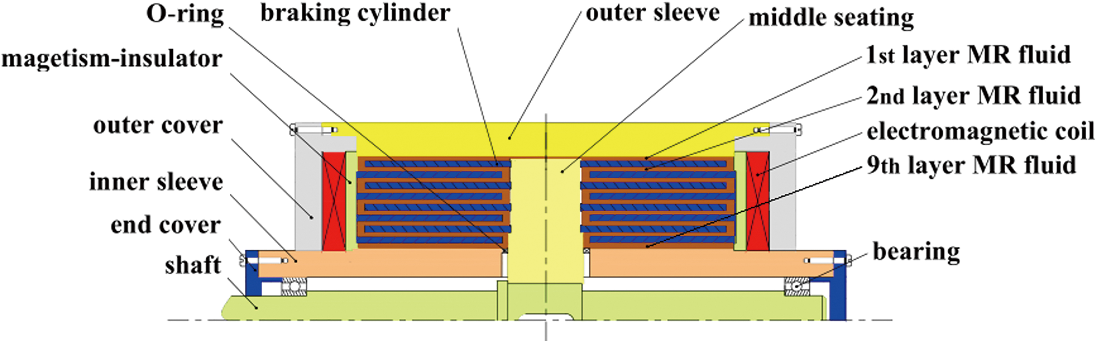
The multi-cylindrical MR brake is equipped with sixteen cylinders totally, and the eighteen gaps are filled with layers of magnetorheological fluid. When the coil is energized, the magnetic flux passes through the working fluid gap to generated shear yield stress, thereby preventing the rotation of braking cylinders and hence produces the main braking torque which is controllable by the input magnitude of the excitation current.
The maximum radial dimension of the brake is 196 mm and the maximum axial dimension is 280 mm. The minimum diameter of the braking cylinder is 35 mm, the wall thickness and length of each braking cylinder are 5 mm and 72 mm respectively, and the each working fluid gap of the magnetorheological fluid is 2.0 mm uniformly.
As for single cylinder MR brake, the torque transmitted by the brake at radius
where
When the cylinder rotates, the magnetorheological fluid’s velocity
where the first term
According to Bingham plastic model, the constitutive relation for shear stress for the MR fluid under magnetic field is given by [13]
where
From Eqs (1)–(4) we can see that the total braking torque
where
where
The MR fluid with high yield stress and low viscosity prefer to apply to output a large braking torque. As a result, the type MRF-J01T MR fluid which is developed by China Chongqing Institute of Materials is chose in this paper. The relationship between the shear yield stress and magnetic flux intensity
where
Magnetic circuit of the proposed MR brake.
If the preset maximum braking torque of this MR fluid brake is 800 N
The magnetic resistance of each part of the magnetic circuit can be obtained by the magnetic circuit Ohm laws in Eq. (9),
where
where
It is calculated by Eqs (9)–(11) that the total reluctance
According to the reluctance Ohm’s law and Kirchhoff’s law that the magnetic flux of magnetic circuit
where
The area of the
where
Limiting to the on-board excitation current source, the maximum excitation current does not exceed 3.0 A. Based on the calculation, when under the conditions of 3.0 A excitation current excitation and the magnetic flux intensity of 0.4 T at the working fluid gap, the number of turns for each electromagnetic coils are 665 turns, approximating to 670 turns. As a result, the copper enameled wire of SWG23-1/3 is selected to maximize the magnetic field.
The magnetic simulation of the multi-cylindrical MR brake is undertaken using the finite element software Maxwell. Two hypotheses and approximate treatment methods are put forward in terms of the actual structure of the multi-cylindrical MR brake. (a) Because MR brake’s boundaries are idealized and the phenomenon of magnetic flux leakage at the boundary is ignored, the balloon is assigned as the boundary type in the magnetic simulation. (b) Shaft, non-magnetic bearings and other structures have been omitted. And the relationship between magnetic field intensity and magnetic flux intensity of MR fluid MRF-J01T is presented as Fig. 3.
Magnetic field intensity versus magnetic flux intensity.
Distribution of magnetic induction lines.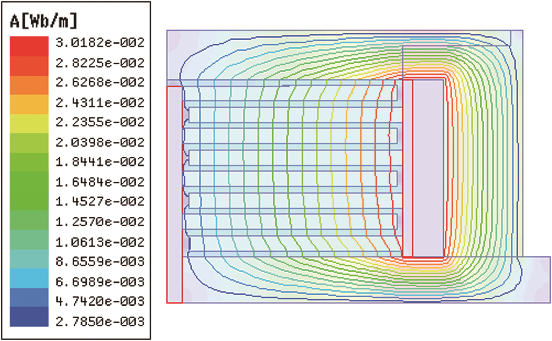
Total distribution of magnetic flux intensity.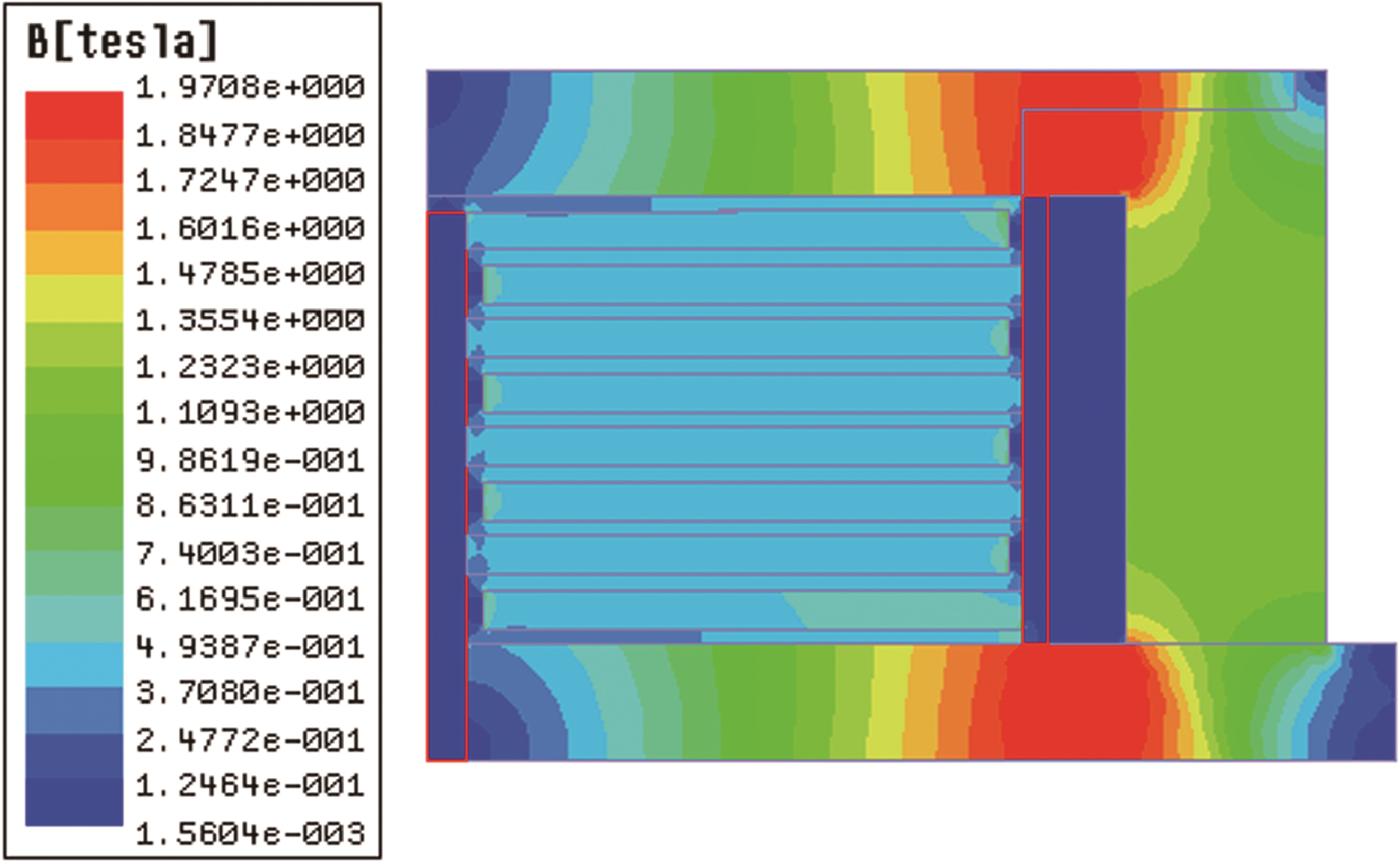
Distribution of magnetic flux intensity in working area.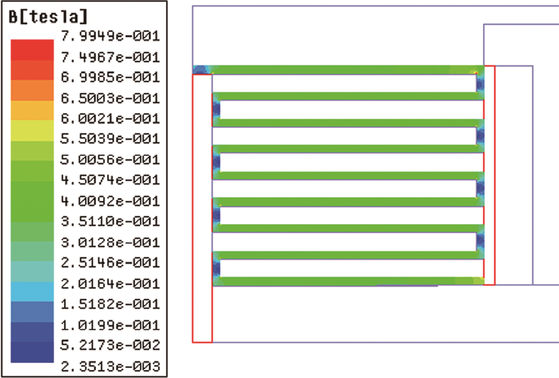
Figure 4 presents the distribution of magnetic induction lines with a excitation current strength of 3.0 A. As shown in Fig. 4, the magnetic induction lines are not only strictly confined in the designed magnetic circuit but also distribute vertically through the individual working fluid gaps. Figure 5 shows the magnetic flux intensity distribution in the magnet yoke of the multi-cylindrical MR brake. The results indicate that the maximum magnetic flux intensity with the value of 1.97 T appears at the outer sleeve, the inner sleeve, and the outer cover which don’t reach the magnetic saturation intensity of 20 steel. It is clearly seen that the magnetic saturation phenomenon does not appear in the whole magnetic circuit, which indicates that the magnetic circuit design is reasonable.
The magnetic flux intensity of the MR fluid’s working area has a significant effect on the magnetorheological effect. Figure 6 shows that under the same excitation current, the magnetic field intensity of MR fluid distributes uniformly in the working area with no phenomenon of magnetic potential decline magnetic field intensity.
Influencing factors of braking torque
Table 1 presents the uniform magnetic flux intensity of different excitation current obtained from the magnetic simulation results. According to the Table 1 and Eq. (8), the variation of the braking torque with the input excitation current is obtained and shown in Fig. 7. It can be seen that the braking torque increases nonlinearly with the increase of the excitation current due to the nonlinear effect of the magnetic circuit material, which tends to be gentle after 3.0 A.
Magnetic flux intensity value of different excitation current
Magnetic flux intensity value of different excitation current
Variation relationship of braking torque with exciting excitation current.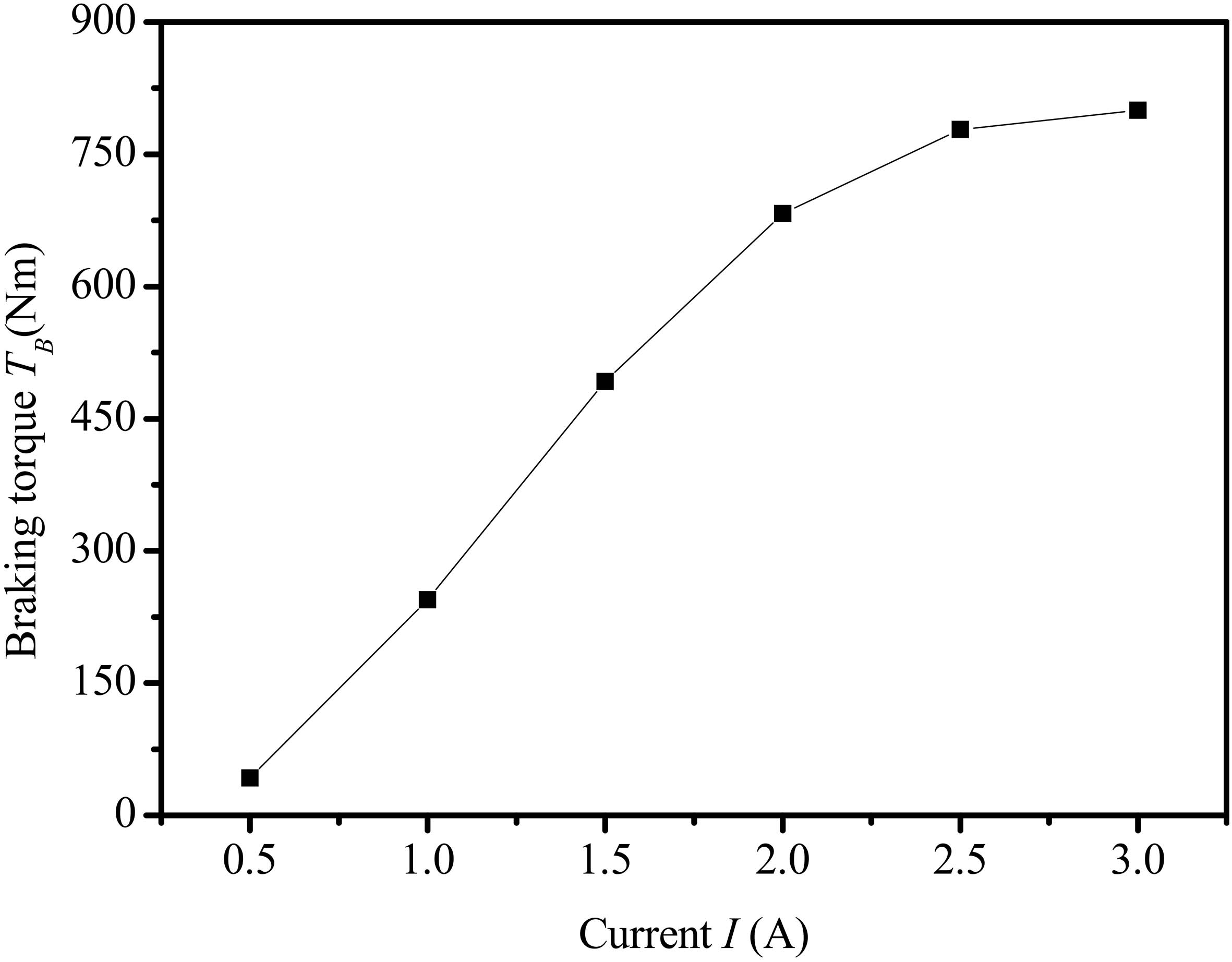
The relationship between the braking torque and the excitation current can be expressed by the quadratic polynomial fitting as Eq. (15). As a result, the braking torque can be controlled by adjusting the excitation current which is helpful to realize the linear control of braking torque.
As for multi-cylindrical MR brake, the braking torque not only influences by the excitation current, but also the number of braking cylinders in deed.
Figure 8 shows the braking torque of different number of braking cylinder with consist excitation current, it indicates that the braking torque increases rapidly with the increase of braking cylinder number at first, and then gradually slowed down to reach its saturated maximum value at eight cylinders. It is similar to the regulation of baking torque versus excitation current with consist cylinder number. The reason of the non-linear variation is that the magnetic flux intensity decreases with the increase of the number of braking cylinders which cause the increase of the magnetoresistance. On the contrary, the braking torque increases with the increasing braking cylinder. However, its growth rate is gradually slowed down to much to resist the increase of magnetic resistance caused by the magnetic potential loss, and leads to the brake torque increasing rate come to decline finally. That indicates that eight numbers of the braking cylinder is the optimal number.
Variation relationship of braking torque with braking cylinder number.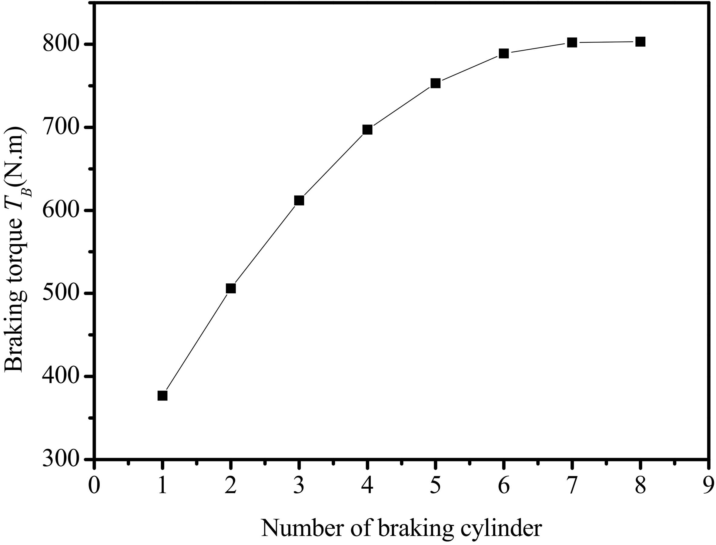
In the process of magnetorheological brake, the magnetic particle chain is constantly under the action of shear force and the mutual friction between the particles, which will inevitably produce a certain amount of heat. The working temperature of MR fluid generally does not exceed 130
Basic parameters
In order to analyze thermal properties of the proposed MR brake the transient temperature are undertaken using the finite element software ANSYS workbench in this paper.
In the simulation process, the Hex domainant, Sweep and Multi Zone methods are used to divide the mesh due to the complexity of the components. The mesh sizes of the MR fluids and other components are set to 1 mm and 2 mm, respectively. In order to improve computational efficiency, several approximate treatment methods are put forward in terms of the actual structure of the MR brake. Such as (a) The components of the MR brake combine closely, and the influence of the thermal contact resistance on the heat conduction is ignored before being introduced into the ANSYS workbench. (b) The braking torque is assumed to be determined as constant values, not varied with the time. (c) The distribution of the heat generation rate in every working fluid gap is considered to be uniform. (d) Assume that the material’s thermophysical parameters are constant during the simulation.
For transient thermal analysis, three material properties including density, thermal conductivity and specific heat are required in ANSYS. Table 2 presents these properties for various components of multi-cylindrical MR brake.
Material properties of each component
Material properties of each component
This section discusses the methodology used for transient analysis of proposed MR brake. The initial ambient temperature was assumed to be 22
Following loads are considered for proposed thermal analysis:
Generation of heat through the action of shearing and friction in the fluid; Generation of heat due to the flow of electric excitation current in the coil; Cooling by convection associated with the flow of air around the system.
Volume and heat generation rate of each layer of the MR fluid
Volume and heat generation rate of each layer of the MR fluid
The power
The every layer effective working volume of MR fluid is given by
where
By assuming that the dissipated energy is all translated into the friction heat causing the temperature rise of MR fluid, the heat generation rate
where
The volume and heat generation of each layer of the MR fluid are calculated and shown in the Table 3.
The heat formed in the coils due to the flow of electric excitation current through it (i.e. Joule heating) can be specified by the resistance of enameled copper wires given by
where
Therefore, internal heat generation in the coil will be:
Heat formed in the coil/Volume of the coil
Both natural convection and heat radiation coexist in the surface of the sleeve and cover. In order to characterise the convection, considering overall consideration of the comprehensive effect, the compound heat coefficient
Referring to the result in literature [17], the value for the compound heat exchange coefficient is usually adopted as
Since the heat exchange coefficient
Result and analysis
The temperature built up within MR brake for transient effects after 20 s has been exhibited in Fig. 9. It is evident that the maximum temperature built up is in the region of MR fluid and the temperature of layers of magnetorheological fluids are distributed from high to low. The maximum temperature within MR brake was found to be 52.283
Temperature distribution contour of MR brake after 20 s.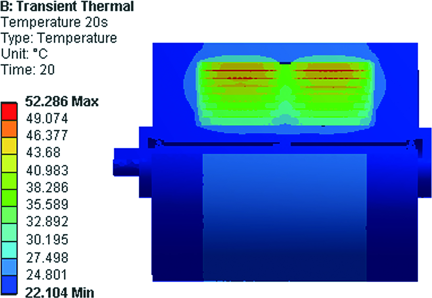
Curve of temperature with time of the first four layers of gaps.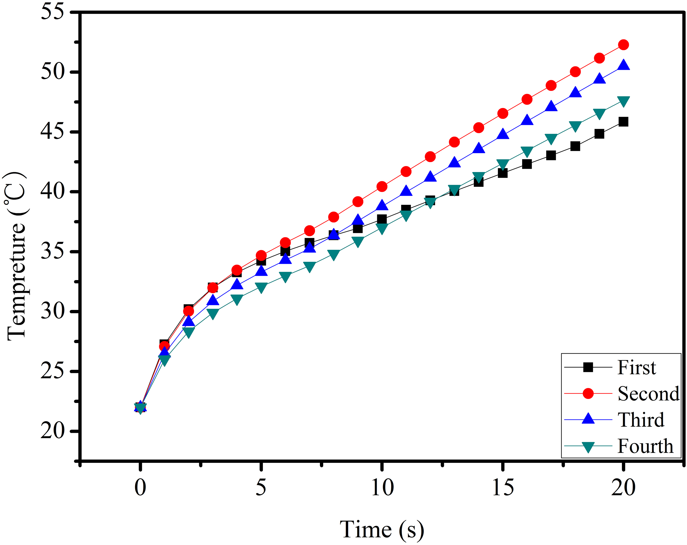
According to the transient temperature profile, the temperature raise characteristic of the heat source especially the first four layers of the MR working fluid gap with higher temperature need to be carefully scrutinized. Figure 10 shows the temperature change curve of the first four layers of the working fluid gaps of the MR brake over the time. It is clearly seen from it that the temperature of each layer of magnetorheological fluid changes significantly with the passage of time, however, there is no tendency toward equilibrium for the curves according to the trend of curve. Among four layers of working fluid gap, the curves of the working fluid gap in layer 2
Temperature distribution contour in the first four layers of MR working fluid gaps; (a) Total and section enlarging; (b) Along to axial length.
The first four layers of the magnetorheological working fluid gap unit are extracted separately to analysis the surface of the magnetorheological fluid in detail. The Fig. 11 shows the temperature distribution of total and along the axial length where is on the contact area of the MR fluid and braking cylinder’s inner surface. It is clearly seen from Fig. 11a that the temperature of each layer of MR fluid is higher in the central part and lower in the edge. At the same time, it is observed from Fig. 11a that the surface temperature is the highest in the axial length from 25 mm to 45 mm with a value of nearly 48.2
According to the thermal simulation study above, the highest temperature rise presents on the second braking cylinder, as a result, the stress of the second braking cylinder need to be analyzed in depth. It can be seen from the Fig. 12 that the braking cylinder temperature rises to 46
Temperature distribution contour of MR braking cylinder.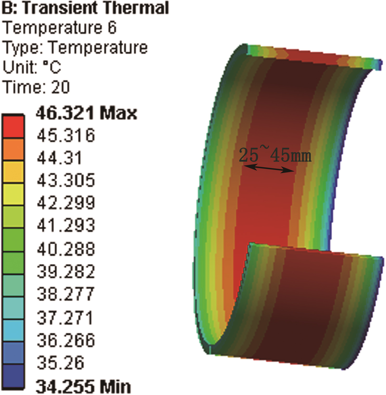
Equivalent stress contour of internal section of MR braking cylinder.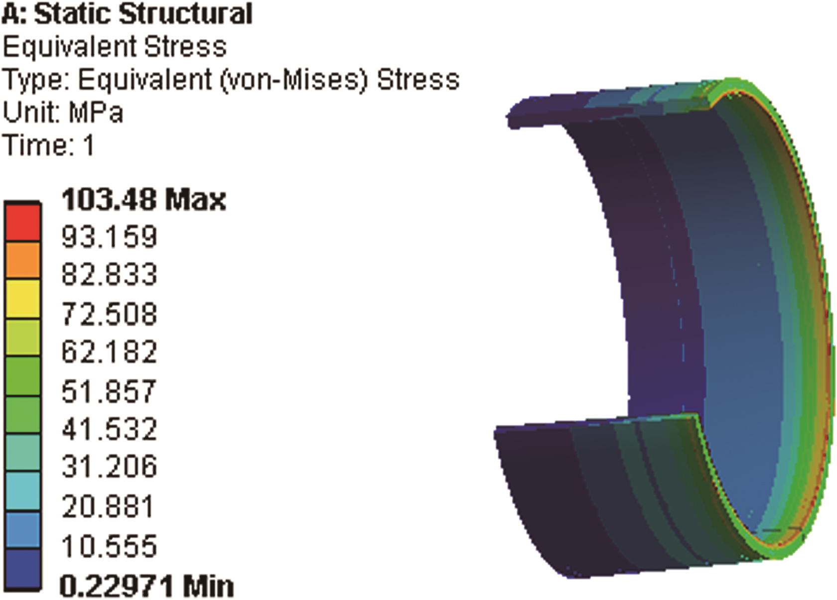
The loads and constraints imposed on the structural stress analysis are as follows: (a) The side of braking cylinder is fixed where is in contact with the magnetism-insulator. (b) Two braking torques are applied to the outer wall surface and inner wall surface of braking cylinder with the value of 57.56 N
In this work, a new structure of a multi-cylindrical MR brake was designed and investigated. A multi-field simulation analysis using the finite element method of magnetic field, heat dissipation and stress state of the multi-cylindrical MR brake was performed. From the magnetic simulation results, it has been identified that the brake’s magnetic circuit design is reasonable with no magnetic saturation phenomenon, and the magnetic flux intensity distribution in the work gap is uniform. The braking torque shows a non-linear increase with the increase of the excitation current and the number of braking cylinders. From the thermal simulation results, it has been shown that the maximum temperature of the multi-cylindrical MR brake appeared in the heat source of MR fluid with a value of 52.3
This type of multi-cylindrical MR brake provides a novel thinking for the research of high torque brakes, especially the MR brake is a linear brake with excellent response speed, which makes the application of the MR brake in the vehicle braking system new possibility. What’s more, with the development trend of the integrated model feature, this allows MR brake to apply to multiple auxiliary systems in automobiles, such as anti-lock braking system (ABS), electronic parking brake (EPB), vehicle stability control (VSC), etc.
Footnotes
Acknowledgments
This project is supported by National Natural Science Foundation of China (Grant No. 51775101), Fundamental Research Funds for the Central Universities (Grant No. N170304017, N130303002), Postdoctoral Science Foundation of China (Grant No. 2017M610181, 2018M631800). This work was also supported by a Northeastern University Research Grant.