
Abstract
Ultra-fast circuit breakers are operated with fast electromagnetic actuators. They can generate a sufficient impulse force to swiftly open electrical contacts in a couple of milliseconds. Opening of the contacts with high velocities implies a need for a timely and controllable damping. An efficient damping mechanism then is crucial to attain an appropriate actuation performance and secure a long lifetime. In this paper a finite element model of a Halbach magnet array based magnetic damper and a corresponding experimental prototype is described. A parametric study is performed to understand the effect of load mass and incoming velocities. It was found that the magnetic field modulation plays an important role on the damping performance. A uniform and high radial component of the magnetic flux density is necessary in order to achieve high damping force. The radial magnetic field can be controlled via thickness and magnetization direction of the ring magnets that are used to create the Halbach magnet array.
Keywords
Introduction
High voltage circuit breakers are one important part of a power system protection. The requirements for these are that they should insulate electrical faults as quickly as possible and also be able to operate as many times as possible without wear and tear during their lifetime. These requirements for breakers with ultra-fast actuators imply the need of an efficient damping mechanism. The current circuit breakers are operated with different drives depending on the voltage and current class they are used for. Some of these are based on spring mechanisms, hydraulics or electromagnetics. Most of them have mechanical drives that limit their operating speeds and lifetime. Electromagnetic based drives can provide higher operating speeds but in this case there are no efficient controlled dampers available that fulfill the above stated requirements.Therefore, research on controlled and efficient dampers is of interest. Different damping principles are used such as friction based damping, viscous damping, gas damping etc. All these damping approaches add wear and tear to the breaker as they use friction force or fluid or gas pressure to decelerate the contacts. Eddy current based damping has attractive features because it involves no friction force or fluid or gas pressure to be maintained. Different eddy current damping topologies have been studied in [1–10]. Most of them use planar magnets as a source of the magnetic field and a conducting armature for the magnetic induction. In [1] a planar magnet array is used to generate an orthogonal damping force on a copper plate. In [2] the difference in the accuracies between analytical and Finite Element Method (FEM) for modelling eddy current dampers is studied. The discussions in [4,5] were focused on optimization and dimensioning of the Halbach cylinder. A rotational eddy current damping mechanism was described in [6,7]. In [8] an eddy current damping mechanism for magnetic levitation was studied. It was summarized in [9] that the Halbach topology renders the highest damping force among different tentative topologies. Therefore, a Halbach magnet array based damping concept was modelled by the use of a finite element method. A prototype was also built to verify the obtained numerical results in [10]. This paper discusses design parameters that effects the damping performance in detail.
Methodology
Eddy current damping is a phenomena based on magnetic induction. Eddy currents are generated in the conductive material due to the relative velocity between the Halbach magnet array and parts made of conducting material. A magnetic field of opposite polarity generated by these eddy currents interacts with the magnetic field of the Halbach array and causes a damping force. In this process kinetic energy of the moving mass that is attached to the conducting material is converted into heat and dissipated in the conducting material.
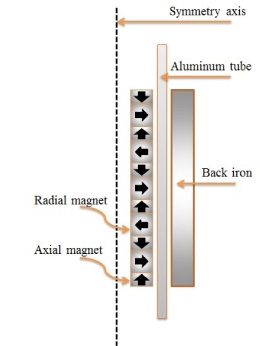
Schematic of the damper with arrows showing magnetisation direction.
Figure 1 shows the build-up and the prototype which is modelled by using the finite element method and validated experimentally. The structure has rotational symmetry. The Halbach array is created by stacking axially and radially magnetized ring magnets. The thin magnets are axially magnetized and the thick are radially magnetized. The Magnetization direction is chosen such that the magnetically weak side of the Halbach array is directed towards the symmetry axis. The Assembly of such a Halbach array is cumbersome. So the whole assembly is simulated and thereafter the magnets then are stacked accordingly. The back iron will provide a low reluctance return path for the magnetic field generated by the magnet array and therefore strengthen the magnetic flux density in the space between the Halbach magnet array and the back iron. An aluminium tube is free to move vertically without any collision or friction in the space between the magnet array and the back iron tube.
The load which is to be damped is attached to the aluminium tube. The intention is to ensure the movement of an electrically conducting material in a region with a high magnetic field created by the stationary Halbach magnet array and the back iron tube. As a result, the moving mass will be damped without any collision or friction. The concept is modelled as a 2D axisymmetric model as shown in Fig. 1 using COMSOL 5.2. A nonlinear B-H characteristic is taken into consideration for the back iron to manage the saturation effect. A separate B-H curve of the permanent magnets from their datasheet are also used in the model. Ampere’s law for magnet array is
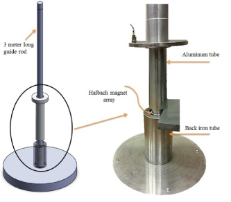
Damper prototype. The left part of figure shows 3D drawing and the right part represents designed prototype.
The setup consists of the Halbach magnet array placed concentrically around a 3 meter high steel guide rod. The back iron is fixed to a solid steel base plate shown in Fig. 2 and concentrically around the magnet array. The aluminium tube is guided by the steel rod and falls in the space between the magnet array and the back iron. This results in a drop tower design. There is very limited friction between the steel guide rod and the moving aluminium tube. Therefore, one can consider it as a free fall. Initial kinetic energies and velocities before the damping starts can be calculated by use of Newton’s equations of motion. The aluminium tube with the load mass is dropped from the top of the tower during the experiments. To measure the velocities of the aluminium tube, it is marked and tracked with a high speed camera with 20000 frames per second (fps).
Figure 3 shows the absolute value of the magnetic flux density in the designed passive damper. The back iron provides a low reluctance path for the magnetic flux so that the aluminium tube is fully exposed to the magnetic field. The radial component of the magnetic flux density induces a current in the aluminium tube in the azimuthal direction and it generates a damping force in the positive z direction. As seen in Eq. (5) the damping force is proportional to the square of the radial component of the magnetic flux density. The zoomed in part in Fig. 3 shows a part of the Halbach passive damper clearly showing the magnetic flux lines and the norm of the magnetic flux density. It is evident from Figs 3 and 4 that by reducing the inner radius of the axially magnetized magnet the magnetic field is fairly uniformly distributed in the region where aluminium tube is moving and it also shows that the magnetic flux density is increased in the aluminium tube.
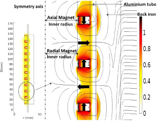
Norm of Magnetic flux density B (T) of the passive Halbach damper and insight picture shows detail magnetic field lines and magnetic flux density.
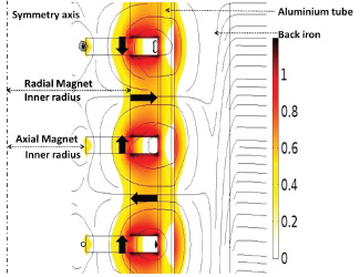
Norm of Magnetic flux density B (T) having axial magnet inner radius 7 mm.
A parametric study is done for different inner radius of the axial and the radial magnet keeping the outer radii constant. The radii are varied from 7 mm to 15 mm in steps of 1 mm and a total of 81 FEM simulations are made. The results of these simulations are shown in Fig. 5. Reducing the radius of only the axially magnetized permanent magnet renders an increase force by around 500 Newtons while reducing the radius of only the radially magnetized magnets gives an increase of force by around 100 Newton. The generated damping force with the designed Halbach array shown in Fig. 1 with a constant velocity of 8 m/s is shown in Fig. 6. a is the back iron thickness and b is thickness of the aluminium tube. Variable b is varied from 0.25 mm to 10 mm in steps of 0.25 mm while variable a is varied from 0.1 mm to 10 mm in steps of 0.1 mm. A total of 4000 FEM based simulations were performed corresponding to the different values of a and b. Increase in b increases the reluctance as the magnetic field lines will reside in the moving aluminium tube that reduces the damping force. While a too small value of a can saturate the back iron. It is observed that a 2 mm thickness of the aluminium tube is optimum for maximizing damping force. The back iron thickness does not affect the damping force significantly. The optimum value is the value for which a large damping force is generated for an affordable aluminium thickness. From Fig. 6 it is evident that there is an optimum region around 2 mm aluminium thickness that gives the largest damping forces. It can be seen from Figs 5 and 6 that the Simulated peak damping force was 1.5 kN for the aluminium tube attached to a 1.2 kg load mass having 8 m/s velocity. The damping force is proportional to the velocity indicating that still higher damping forces can be achieved. The results from the built prototype Fig. 2 and simulations are shown in Figs 7 and 8. The aluminium tube is dropped from different heights of the tower. The tower is 3 meters high. It is observed that there is negligible friction between the aluminium tube and the steel guide rod. Therefore the aluminium tube enters the magnetic field zone with different incoming velocities. The load mass connected to the aluminium tube for experiments that are shown in Fig. 7 is 1.25 kg and 0.25 kg for the experiments that are shown in Fig. 8. The Simulation results in Fig. 7 show that the damping time is around 60 ms and after that a stationary velocity of 0.08 m/s is reached. Where in the case of 0.25 kg mass the damping time is around 30 ms before the aluminium tube reaches stationary velocity. The experimental results matches quite well with simulations. It is observed that in Fig. 7 the experiment with incoming velocity of 7.2 m/s the aluminium tube collides with the base plate at 38 ms so the velocity curve falls to zero. The simulation does not follow the experiment in this case. This is because the direct collision between the aluminium tube and the base plate is not modelled in the simulations.
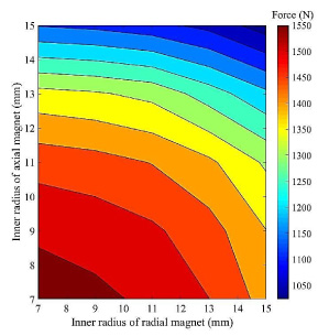
contour plot showing damping force for different radius of axial and radial magnet.
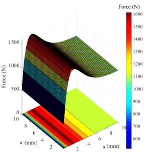
3-D plot of the damping force as a function of the thickness of the aluminum tube a and the thickness of the iron tube.
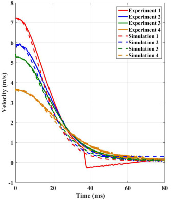
Simulation and experimental results comparison with load mass 1.25.
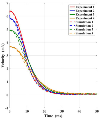
Simulation and experimental results comparison with load mass 0.25 Kg.
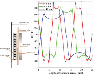
Radial component of the magnetic flux density over halbach array with three different thickness t of radial magnet.
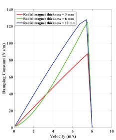
Damping constant as a function of velocity for three different thickness of radial magnet.
Figure 9 shows the profile of the radial component of the magnetic flux density in the region where the aluminium tube is moving. It can be seen that the designed Halbach array gives a modulated radial magnetic flux density. The frequency of this magnetic field modulation depends on the thickness of the axially magnetized and radially magnetized magnets. By keeping the thickness of the axially magnetized magnet constant and changing the thickness of the radially magnetized magnet gives the magnetic field profiles are obtained as shown in Fig. 9. It is clear from the Fig. 9 that the period of the magnetic field modulation is proportional to the sum of thickness of radially and axially magnetized magnets. The corresponding damping constant as a function of velocity is shown in Fig. 10. It is evident that the damping constant is higher for the 10 mm thickness of the radially magnetized magnet for velocities ranging from 0 to 8 m/s. It is interesting to see that the structure with the radially magnetized magnet with 3 mm thickness results in a higher damping constant for velocities upto 3 m/s compared to the radially magnetized magnet of 6 mm thickness.
It was shown that the simulation and experimental results agree quite well. It is concluded that the Halbach arrangement of magnets provides a high radial magnetic field and a higher damping force compared to conventional spring and hydraulic dampers. The magnetic field modulation effects the damping constant. The magnetic field modulation can be controlled by choosing appropriate design parameters. It was also seen that the concept provides collision-free damping with a considerably higher damping force compared to results shown in [9]. The damping forces reported in [9] are ranging from 251 N to 988 N for 5 m/s velocity. Finally, it is concluded that the studied concept is feasible for applications where there is a need for higher damping forces and higher initial velocities than conventional dampers can manage.
Footnotes
Acknowledgements
This work was funded through SweGRIDS, by the Swedish Energy Agency and ABB. The authors would also like to thank Jesper Freiberg for his efforts in manufacturing the prototype.