
Abstract
The elastic characteristics of transformer winding materials have an important influence on its deformation due to short-circuit (SC) fault. This paper presents an electromagnetic-thermal-fluid-mechanical coupling analysis method for dynamic deformation calculation of power transformer windings under SC fault, considering the influence of temperature on modulus of elasticity of winding materials. The dependence of modulus of elasticity of spacer and copper conductor on temperature in transformer windings are tested by dynamic thermal mechanical analyzer. The transient dynamic response of windings deformation including mechanical stress and displacements, as well as temperature distribution, for an oil-immersed-type 110 kV power transformer due to SC are obtained using the proposed method. The maximum stress and displacement achieved by the proposed method is greater than that calculated neglecting the temperature dependence of elasticity of modulus of winding materials. The upper part of the winding are more susceptible to damage due to SC impact.
Introduction
Power transformer is one of the most important equipments in power systems. Deformation of power transformer windings due to the large electromagnetic force under the short-circuit SC condition has been one of the major faults of power transformer [1,2]. Therefore, it is necessary to understanding the dynamic response to SC fault of transformer windings and predict winding deformation state accurately in the transformer design. The SC experiment on large power transformers is the direct means to examine its ability to withstand SC, but these experiments are pretty expensive and the test transformer will be damaged [3–5]. So the precise numerical analysis of the dynamic deformation of transformer windings under SC fault is of great significance to the design and manufacture of transformer. The numerical simulation techniques are used to investigate deformation of transformer windings in many publications [6–9].
It is known that the temperature of different positions of transformer windings is different, and the internal temperature of the transformer rises rapidly during the external SC fault [10–13]. The elasticity characteristics of winding materials, determining the relationship between stress and deformation of windings, is closely related to temperature [2], and will also change during the SC fault, so that the dependence of elasticity characteristics of winding materials on temperature affects the dynamic deformation and stress of transformer windings under the SC fault. However, most of these researches on dynamic deformation of power transformer windings due to SC fault didn’t take into consideration the effect of temperature on the elasticity characteristics of winding materials currently. In this paper, the change rule of modulus of elasticity of the spacer and copper conductor in windings with temperature was measured by dynamic thermal mechanical analyzer (DMA). Further more, a two-dimensional (2-D) axisymmetric finite element model of a 110 kV power transformer is built. The electromagnetic-thermal-fluid-mechanical coupling analysis is conducted in computation of the dynamic deformation of transformer windings under the SC fault, considering the temperature distribution and the temperature dependence of elasticity characteristics of winding materials.
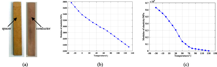
Test sample and modulus of elasticity of winding material. (a) Test sample of spacer and conductor. (b) Modulus of elasticity of spacer. (c) Modulus of elasticity of copper conductor.
The DMA, model number SDTA861e, is used to measure the modulus of elasticity of spacer and copper conductor in windings at different temperature. The test samples of spacer and copper conductor are shown in Fig. 1(a), and the sample of spacer is oil-immersed before the measurement to ensure the accuracy of the test result. Figures 1(b) and 1(c) show the dependence of modulus of elasticity of spacer and copper conductor on temperature in the range of −30–130 °C respectively. With the increase of temperature, the modulus of elasticity of spacer and copper conductor all decrease, but the modulus of the spacer blocks decreases faster with temperature than that of copper conductors.
Coupling method and calculation principle
When SC fault occurs in power system, high-magnitude currents will flow into the transformer windings and produce huge leakage flux. The SC current in the winding interacts with the leakage magnetic field of the winding, so that the windings are subjected to strong transient short-circuit electromagnetic force and may occur serious winding deformation and vibration. At the same time, the large short-circuit current makes the loss and temperature of transformer rise rapidly.
The electromagnetic-thermal-fluid-mechanical coupled analysis is conducted in the dynamic deformation of transformer windings under the SC fault based on finite element method (FEM). The influence of modulus of elasticity of winding materials at different temperature on dynamic deformation of power transformer windings has been considered.
Electromagnetic Field and loss calculation
The heat sources inside the transformer mainly come from the transformer core and windings when it is running or suffering the SC fault, which can be obtained by electromagnetic analysis. According to the Maxwell’s equation, the transient electromagnetic field of transformer can be achieved as follows [3]:
Electromagnetic force density in transformer windings can be obtained by (2) as follows:
Transformer energy loss are generated from core and copper conductor. These losses are considered as the heat sources of transformers that causes temperature rise during its operation and SC fault. The core loss can be calculated base on (3) [8].
Winding DC loss is the main part of winding loss. Winding loss is calculated considering the relationship between winding resistance and temperature is linear. And winding loss P (T) is modified according to winding temperature, based on (4) [8].
Compared with heat conduction and heat convection, heat radiation can be ignored. So only the heat conduction and heat convection are considered in calculation of temperature field. The governing equations to calculate the temperature field are shown as follows [10]:
Transformer oil has the properties of slow speed and high viscosity, so the laminar flow model was adopted in the coupling analysis. Oil flow influence on the temperature field distribution is considered in the simulation. The fluid field can be obtained through solving the mass conservation equation, momentum conservation equation and energy conservation equation, described as follows [10].
Stress, strain, displacements, and other computation variables are assumed as symmetry relative to Z axis. In cylindrical-coordinate system, the relationship between the computation variables in copper disks or spacer may be expressed as follows [1]:
Equilibrium differential equation expresses the relations between stress and mass force in space.
Geometry equation expresses the relations between strain and displacements in space.
Figure 2 shows the flowchart of electromagnetic-thermal-fluid-structure coupling analysis, which includes two parts, namely calculation under rated operation condition and SC fault condition. Transformer losses under the two condition are taken as the heat sources in the analysis of the two parts, respectively. The thermal field distribution under rated operation condition, as the initial value of the transient electromagnetic-thermal-fluid-structure coupling analysis under the SC fault condition, is achieved through steady electromagnetic-thermal-fluid coupling field calculation in the first part shown in Fig. 2.
The transformer material properties, which are dependent on temperature, including thermal conductivity 𝜌, kinetic viscosity u, heat capacity at constant pressure of oil C
p
, electrical conductivity of copper d, modulus of elasticity of copper and spacer E, are updated during the process of coulpling calculation according to the Eqs (12), (13), (14), (15).
The pressure and load from the oil act on the windings, and the windings vibration velocity also act as a boundary condition on the oil. The interreaction between oil and windings can be calculated by fluid-structure coulping analysis according to the Eq. (16).
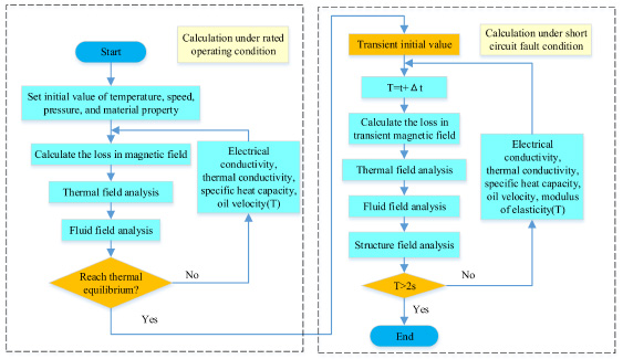
Flowchart of electromagnetic-thermal-fluid-structure coupling analysis.
Specification of the 110 kV power transformer
Therefore, the dynamic stress and displacement of transformer windings can be obtained through transient electromagnetic-thermal-fluid-structure coupling analysis during the SC fault, considering the influence of temperature on the modulus of elasticity of copper conductor and spacer.
2-D finite element model of power transformer
The coupling method proposed is used to investigate the dynamic deformation of a 110 kV oil-immersed power transformer, including high-voltage (HV), medium-voltage (MV) and low-voltage (LV) windings. The 2-D finite element model of A phase winding of the power transformer is shown in Fig. 3. Table 1 presents the detailed parameters of the power transformer. The short-circuit current under the condition of three-phase short-circuit fault is shown in Fig. 4.
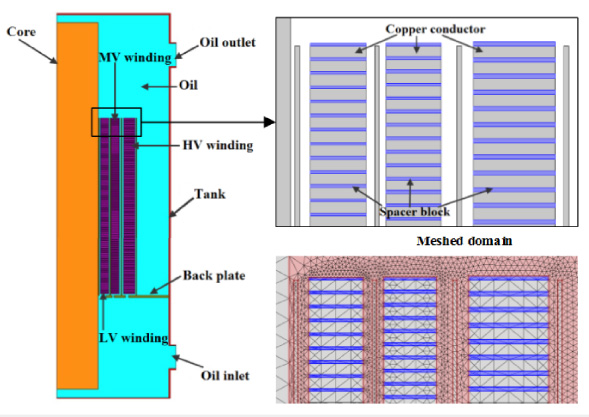
2-D finite element model of power transformer.
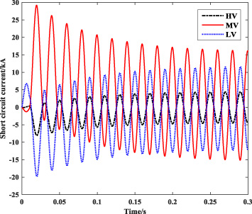
Transient short-circuit current in different windings.
The temperature distribution inside the transformer under the rated operating condition is obtained through the steady electromagnetic-thermal-fluid coupled analysis, presented in Fig. 5(a). It can be seen from Fig. 5(a) that the highest temperature inside the transformer occurs in the LV winding and reaches 87 °C under the rated operating condition. The steady analysis result shown in Fig. 5(a) is used to be the initial value in the the transient electromagnetic-thermal-fluid-structure coupling analysis during the SC fault condition.
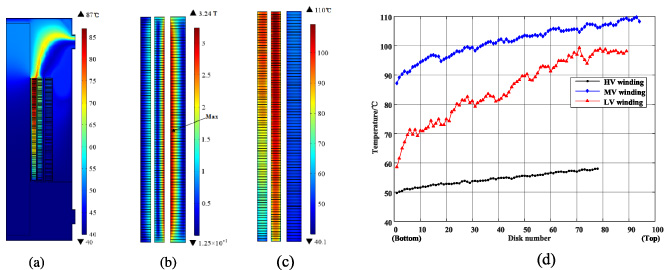
Results of magnetic and thermal field. (a) Thermal field distribution under rated operation condition. (b) Leakage flux density distribution at peak SC current. (c) Temperature distribution under SC condition at 0.2 s. (d) Temperature distribution of winding disks under SC condition at 0.2 s.
The distribution of magnetic field, thermal field, fluid field, and structure field inside transformer due to the SC fault is achieved through the transient coupling analysis based on the method shown in Fig. 2. Figure 5(b) presents the leakage flux density distribution at peak SC current, and the maximum leakage flux density, 3.24 T occurs in the middle of the HV winding. Figures 5(c) and 5(d) illustrate the temperature distribution of the transormer under SC condition at 0.2 s. It can be seen from Fig. 5(d) that the temperature of upper disk of the windings is higher than that of lower disk of the windings, and the temperature of MV winding is relative higher than that of HV and LV windings, because of the maximum SC current value in MV winding. The highest temperature of the transformer, 110 °C, occurs at the top of the MV winding at 0.2 s.
Figures 6 and 7 illustrate the transient radial and axial electromagnetic force in MV winding disks. The MV winding disks are numbered from top to bottom of the wingdings. It can be seen that the maximum radial electromagnetic force occurs in the middle disk of MV winding, while the minimum one occurs in the end disk of MV winding during SC fault. The maximum axial electromagnetic force is at both ends of the wingdings. The MV winding is squeezed by the axial electromagnetic force from both ends to the middle of the windings during the SC fault, shown in Fig. 7. Both the axial and radial electromagnetic forces decrease rapidly with the increase of short-circuit time.
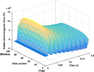
Radial electromagnetic force of MVwinding.
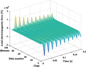
Axial electromagnetic force of MVwinding.
Figure 8 presents the velocity distribution of oil inside transformer at peak SC current. Stress and displacement distribution of windings at peak SC current are shown in Fig. 9, and the maximum stress and displacement occur in the middle disk of HV winding.
In order to compare the results obtained by the proposed method in this paper, the current method, electromagnetic-structure coupling analysis for the transformer winding under SC fault, is also performed and the dynamic deformation of the windings is achieved, neglecting the influence of temperature on the modulus of elasticity of winding materials. The modulus of elasticity of copper and spacer at annual average temperature 20 °C, namely 83724.8 MPa and 3208 MPa based on the test result in Fig. 1, respectively, are used in electromagnetic-structure coupling analysis. The maximum stress and displacement of transformer windings during SC fault are obtained with these two methods, respectively, presented in Figs. 10 and 11. From the Figs. 10 and 11, it can be known that the maximum stress and displacement of transformer windings obtained by the proposed method shown in Fig. 2 is greater than that achieved by the current method, namely electromagnetic-structure coupling analysis.
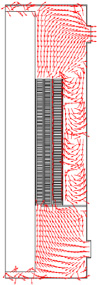
Velocity distribution of oil at peak SC current.

Stress and Displacement distribution of windings.
As Fig. 10 illustrates, the waveform of the maximum stress in windings with time during the SC fault, obtained by current menthod, is pretty similar to that of the dynamic electromagnetic force acting on the windings as the Figs. 6 and 7 shows, so does the maximum displacement in windings. However, the waveform of maximum dynamic stress and displacement calculated by the proposed method, presented in Figs. 10 and 11, respectively, is quite different from that of dynamic electromagnetic force as the Figs. 6 and 7 shows. It is because the influence of temperature on the nonlinear elastic characteristics of the winding material is considered in the proposed method. The temperature of each part of the winding, as well as the elasticity of modulus, is different and varies during the SC fault, So that the relationship between the excitation and response, namely electromagnetic force and winding deformation, is no longer linear.
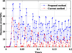
Maximum stress of transformer windings.
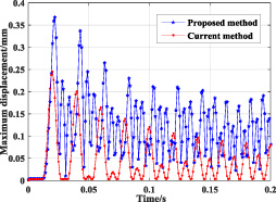
Maximum displacement of transformer windings.
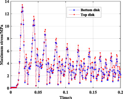
Maximum stress of MV winding

Maximum displacement of MV windings.
Figures 12 and 13 illustrate the dynamic maximum stress and displacement of the bottom and top disk of MV winding under the SC fault by the proposed method, respectively. It can be seen from Fig. 12 that the maximum stress of the top disk is bigger than that of the bottom disk in MV winding, so does the maximum displacement, shown in Fig. 13. The reason for that is the temperature of the top disk is higher than that of the bottom disk, presented in Fig. 5(d), and thus the modulus of the elasticity of the top disk is less than that of the bottom disk, based on the test result illustrated in Fig. 1. The transformer model is symmetrical up and down, so does the electromagnetic force acting on the windings. When the transformer winding is suffered by symmetrical electromagnetic force, the smaller the elastic modulus of the winding material, the more severe deformation and the greater the stress occurs. So the upper part of the winding is more susceptible to damage due to SC impact, which is consistent with the damage characteristics of the windings in engineering practice [6], and illustrates the validity of the proposed calculation method.
An improve method for dynamic deformation calculation of power transformer windings under SC fault based on electromagnetic-thermal-fluid-structure coupling analysis is proposed, considering the influence of temperature on elasticity of modulus of winding materials. The maximum stress and displacement obtained by the proposed method is greater than that achieved by current method, neglecting the temperature dependence of elasticity of modulus of winding materials. The upper part of the winding is more susceptible to damage due to SC impact. The dependence of elastic characteristics of winding materials on temperature can’t be neglected and it can affect the accuracy of winding deformation calculation.
Footnotes
Acknowledgements
This project is supported by National Natural Science Foundation of China (51577140).