This paper presents a simulation of magnetization process of a high-Tc superconductor (HTS), which is used for undulator magnets of X-ray Fee Electron Laser. The numerical analysis is carried out by a current vector potential method (T-method). In particular, it is discussed to use a power law macro-model for behavior of shielding current in the HTS. It is shown that the power low macro-model provides us better agreement with measurements for the final stage magnetic field distribution compared with conventional simulations based on a critical current macro-model.
The X-ray Free Electron Lasers (XFEL) is expected to be effectively used for various kinds of advanced technologies such as observation of pico-second phenomena in atoms. One of the most important tasks in the development of the XFEL machine is downsizing since there exist only a few big machines at the present time. In general, the undulator in the XFEL is very long size and thereore the XFEL itself becomes a big size machine of order of hundred meters. Then it is known that very strong magnetic field is needed in its undulator magnets for the achievement of the compact XFEL undulator. For this, it is considered to apply the High-Tc Superconductor (HTS) to the FEL undulator [1,2]. It is also known that very pure sinusoidal distribution of the undulator magnetic field is required for the FEL operation. Then a numerical simulation plays a very important role in design of the HTS undulator magnets since it is very difficult to adjust alignment and size of the HTS magnets of the undulator after superconductors are magnetized all togather inside a cryostat. From this point of view, authors has been working in development of a numerical simulation code for the HTS magnetization process of the FEL undulator using the T-method combining with a critical state macro-model for the HTS [3]. However it is needed to adjust the value of the critical current Jc in the critical state macro-model to obtain agreements with measurements on the magnetic field distribution. In this paper, we discuss to apply a power low macro-model for the HTS to obtain agreements with the measurements using the real value of Jc.
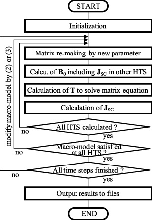
Flowchart of simulation of magnetization process of HTS undulator.
Numerical analysis of HTS magnetization process based on T-method
We here employ the following current vector potential method (T-method), (where σ is conductivity, B0 is externally applied magnetic field, S is the surface of the HTS) which is a kind of numerical schemes of eddy current analysis, for the calculation of a shielding current JSC = ∇ × T induced inside the HTS during the magnetization process. In the previous work [3], we assumed that the shielding current JSC was described by the following critical state macro-model [4,5], instead of the standard Ohm’s low J = σE. Then, the value of the critical current Jc is assumed to be a constant (Bean’s model). A simulation flowchart is indicated in Fig. 1. In each time step of the magnetization process simulation, iterative calculations (the middle loop of Fig. 1) are carried out to satisfy the macro-model relation (2) between JSC and E in everywhere of all HTS undulators (where, we employ an artificial conductivity schme [4,5] which is equivalent to (2) since it is difficult to obtain the electric field E from T directly). Then, the magnetic field produced by other HTS has to be included in the external magnetic field B0 in the simulation of the induced shielding current at the individual HTS. It was confirmed that the magnetic field distribution beyond the HTS undulator showed a good agreement with measurements [1,3] by adjusting the value of Jc. However the adjusted parameter of the critical current Jc of the undulator HTS was taken to be different value from that in the measurements. In this work, the following macro-model of power law conductivity [6,7], (where Ec and N are parameters of the power law macro-model) is employed to obtain agreements with measurements using the true value of the critical current Jc in the measurements. The simulation flowchart is same as Fig. 1. Just the relation (2) is replaced by (3) in the power law macro-model.
Numerical examples
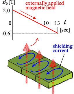
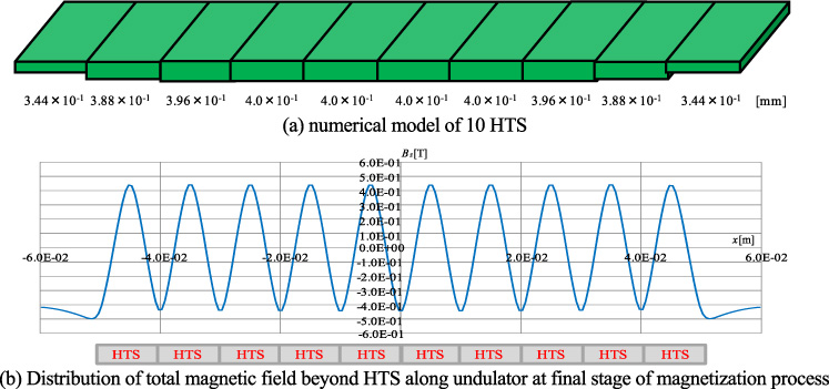
A numerical model of a prototype HTS undulator which was developed for the compact XFEL, called Pure-Type HTS undulator [1], is indicated in Fig. 2. Three HTS plates are placed in serial along the electron trajectory. When an external magnetic field B0 is applied to vertical direction and reduced gradually, the shielding current is induced in the HTS due to the change of the magnetic field. The shielding current at the final stage of the magnetization forms sinusoidal distribution of the vertical component of the magnetic field beyond the HTS, which is used as the undulator magnetic field.
Three HTS Pure-Type undulator.
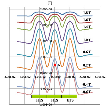
Distribution of total magnetic field along undulator in magnetization process (B0 is from 2.0 to −0.6 [T]) which is simulated by critical state model with Jc =7 ×10⁸.
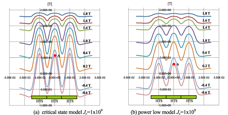
Distribution of total magnetic field along undulator in magnetization process (B0 is from 2.0 to −0.6 [T]).
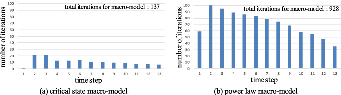
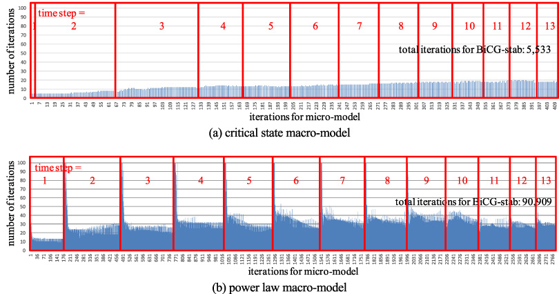
The T-method scheme of (1) is calculated by using the Finite Difference Method (FDM). The individual HTS of Fig. 2 is discretized as 24 × 34 × 8 grids. In Figs 3 and 4, simulation results of the magnetic field beyond three HTS are depicted for each stages of |B0| = B0 = 2.0 T to −0.6 T. The all plots indicate superposed field of the external magnetic field B0 and the magnetic field created by the shielding current JSC in the HTS. Figure 3 is for the critical state model with Jc = 7.0 × 10⁸ [A/m2], which had good agreements with the measurements [1,3] but the value of Jc was different from the true value, Jc =1.0 × 10⁹ [A/m2], in the experiment. Figure 4(a) and (b) indicate results for the true value Jc by the critical state and power low macro-models, respectively. We can find that the good agreement with Fig. 3 (that is, good agreement with the measurements [1]) is obtained in the power low macro-model with the true value Jc. Indeed, relative errors of the maximum value of the magnetic field at the final stage (marked as “A” in Figs 3 and 4) compared with the measurements are 23.7%, 76.5% and 20.2% for Fig. 3, Fig. 4(a) and (b) respectively. In Fig. 5(a), the numerical model of 10 HTS undulator is shown, and the sinusoidal magnetic field distribution at the final stage of the magnetization, which is simulated by the power law macro-model, is depicted in Fig. 5(b). Even for the larger number of HTS, uniform sinusoidal distribution of the magnetic field, which is the same result as that of the critical state macro-model with Jc = 7.0 × 10⁸ [A/m2] [3], is obtained by the true value of Jc. On the other hand, comparison of CPU time between the critical state and power law macro-model is indicated for the number of HTS of the Pure-type undulator, 3, 10, 20 HTS in Table 1. It is readily found that the magnetization simulation of the HTS undulator by the power law macro-model takes much longer CPU time than the critical state macro-model although the power law macro-model provides us reasonable simulation results. For reference, the number of iterations for satisfying macro-model (the middle loop of Fig. 1) in each time step are indicated for the case of 3 HTS in Fig. 6. The result for the critical state macro-model is in Fig. 6(a), and Fig. 6(b) is for the power law macro-model. In addition, the number of iterations in a matrix solver (BiCG-stab method) for the each macro-model iteration is shown in Fig. 7 for the both macro-models. We can understand that the reasons of the long CPU time in the simulation by the power law macro-model are both of the larger number of iterations for macro-model and iterations in the matrix solver compared with those of the critical state macro-model. This means that we need to take into account reduction of the number of both iterations for speed up of the simulation of the magnetization process of the HTS undulator by the power law macro-model.
Numerical example of 10 HTS by power law macro-model.
The number of iterations for macro-model for each time step (3 HTS magnetization simulation).
The number of iterations in BiCG-stab for iteration for macro-model (3 HTS magnetization simulation).
Comparison of CPU time for critical state and power law macro-model
CPU TIME
3 HTS
10 HTS
20 HTS
280 HTS
Critical state
18 min.
2 hours
8 hours
68 hours
Power low
4 hours
20 hours
68 hours
—
Conclusion
To aim to find more suitable simulation scheme for the HTS undulator magnetization process, the power law macro-model for the shielding current in the HTS are employed instead of the critical state macro-model in the conventional analysis. It was shown that the power law macro-model gives us the better agreements with the measurements on the magnetic field distribution at the final stage of the magnetization process with the true value of Jc compared with the critical state macro-model. On the other hand, it was also found that the simulation by the power law macro-model takes much longer CPU time than that of the critical state macro-model. For example, there are over two hundreds magnets in the existing XFEL undulator, therefore, we need to effectively reduce the CPU time of the simulation by the power law macro-model for its practical use in the design of the HTS undulator. One of possibilities of speed-up the simulation is finding of optimal parameters of Ec and N in the power law macro-model to reduce the number of iterations. We will try to find appropriate values of the parameter as a future work.
References
1.
TanakaT.TsuruR. and KitamuraH., Pure-type superconductor permanent magnet undulator, J. Synchrotron Radiation12 (2005), 442–447.
2.
TanakaT.HaraT.KitamuraH.TsuruR.BizenT.MaréchalX. and SeikeT., Application of high-temperature superconducting permanent magnets to synchrotron radiation sources, Phys. Rev. Spec. Top. – AC.7 (2004), Art. ID 090704.
3.
DeriY.KawaguchiH.TsuchimotoM. and TanakaT., Simulation of magnetization process of pure-type superconductor magnet undulator based on T-method, Physica C518 (2015), 106–110.
4.
SugiuraT.HashizumeH. and MiyaK., Numerical electromagnetic field analysis of type-II superconductors, Int. J. Appl. Electromagn. Mater.2 (1991), 183–196.
5.
TsuchimotoM.DemachiK. and ItohI., Numerical evaluation of uniform magnetic field within superconducting Swiss roll, Physica C412–414 (2004), 719–722.
6.
KamitaniA.TakayamaT. and IkunoS., Numerical simulation of inductive method and permanent magnet method for measuring critical current density, IEEE Trans. Magn.44 (2008), 926–929.
7.
KamitaniA. and TakayamaT., Numerical simulation of shielding current density in high-temperature superconducting film: influence of film edge on permanent magnet method, IEEE Trans. Magn.48(2) (2012), 727–730.