



Abstract
In order to choose electric machines for transport applications, i.e. automotive, aerospace, railway and naval, a tool that can make quick tradeoffs of high specific torque electric motors has been developed. The level of the different technologies involved in an electrical machine can be quantified using the loadability concepts developed by experienced designers. After recalling these concepts, magnetic, electric and thermal balances are used to calculate the main sizes of an electric motor according to some targets. Specific power or specific torque can then be quickly assessed. The proposed approach is validated by applying the tool to some known high torque industrial motors.
Introduction
Useful loadability concepts have been developed by electric motor experienced designers [1]. For instance the effectiveness of magnetic and electric technologies to produce torque can be assessed by the magnetic shear stress [2]. In this work, these concepts are exploited to develop a tool to evaluate quickly available electric machine technologies such as winding, cooling or magnetic technology. This tool based on analytical calculation helps to make rapid tradeoffs on high specific torque motors for instance. Among the output data of this tool, there are the main sizes of different parts of the electric machine and its specific power or specific torque. On the other hand many assumptions are done. The tool is evaluated by comparing its results with the performance of industrial machines [4]. As these industrial machines have a relatively low speed, the iron loss can be neglected in front of Joule loss in the winding. For the same reasons the effect of eddy currents in Joule loss are not taken into account.
The main loadability concepts are recalled first from the analytic expression of the torque of an ideal sinewave synchronous motor and the Joule loss in electric motors. After giving the input and output data of the tool, magnetic, electric and thermal balances are presented to calculate the main sizes of electric motors. Finally the performances obtained from the developed tool are compared to some known industrial performances.
The loads of an electric motor from the torque and Joule loss expressions
The magnetic and electric loads are useful concepts presented in many text books [1]. The assumptions of the proposed approach are presented. An ideal sinewave electric motor is defined by two sinewaves: the airgap radial magnetic flux density B and the surface current density K. These two waves are supposed to be localized on the stator bore of axial length, L, and radius, R. Applying Laplace and the action re-action laws, the expression of torque applied on the rotor of a synchronous motor [3] is:
The torque expression (1) defines two load notions, the airgap flux density which is B
rms
and the magnetic shear stress σ defined by:
Using the classical expression of resistance, the Joule loss can be expressed as:
From the previous defined loads and the magnetic, electric and thermal balances defined in next section, a tool has been developed to assess the performances of an electric machine. This analytical tool is based on different choices given in Table 1. The model of the motor studied is shown in Fig. 1. The design of an electric motor starts from the main mechanical specifications which are the rated speed and power. The thermal specifications are the ambient temperature and the maximum temperature on the external surface of the stator frame. The levels of magnetic, insulation and cooling technologies are chosen through the previously defined loads. Finally, some geometrical parameters are chosen (Table 1).
Input data of the assessment tool
Input data of the assessment tool

Main dimensions of the motor studied.
One of the aims of the assessment tool is to roughly calculate the main sizes of the motor and the mass of the motor from the input data. The main dimensions calculated are: the external stator radius R out , the radius bore R, the axial active length L, the slot height h s , the stator yoke height h y , the slot width l s and the teeth width l t at the bore radius. From the input data and the output data, specific torque and specific power can then be calculated.
Neglecting the reaction flux, the magnetic flux conservation law between the flux per pole and the flux in the stator yoke leads to the yoke thickness:
The magnetic flux conservation law between the flux per pole and the total absolute flux in the teeth allows to obtain the total circumferential length of teeth:
In our model, we consider slot of rectangular form of radial height h
s
and circumferential width l
s
. Considering that the fill factor of slot is k
fill
and the number of slots is N
s
(equal to the number of teeth N
t
), the ampere turns balance leads to the slot height:
In the example in the last section, only low speed electric motors are considered. Thus only Joule loss in winding are taken into account. It is assumed that the electric motor is cooled only from the external stator surface. This surface, with external radius R
out
, has a convective coefficient transfer, h
cv
. If radiation transfer is neglected:
Performances of electric motors are mainly limited by thermal constraints in insulation materials of windings. From their experiences, designers have defined the loads that have been presented in the previous section. They may be used to know the technological limitations of electric motor. The permitted levels of loading presented below are extracted from [1]. The magnetic shear stress level (2) measures the capability of electric machines to produce torque and depends on the cooling system efficiency. One knows that fixing shear stress level is the starting point of the sizing of an electric motor. Table 2 gives limitation levels of the magnetic shear stress in synchronous motor independently of their sizes and according to the cooling technology and their types.
The product A rms j rms of the rms current per unit length and the rms current density (4) gives the level of Joule loss according to the cooling technology. They measure the level of insulation technology to support thermal constraints. Indeed Table 2 is given from present insulation technology but it may change with the technology progress.
Permitted values of magnetic shear stress, RMS current per unit length and surface current density in synchronous motor
Permitted values of magnetic shear stress, RMS current per unit length and surface current density in synchronous motor
The airgap flux density appears in the expression of the magnetic shear stress (2) and the stator dimensions (5–6).
For the same level of shear stress and current density, the highest is the airgap flux density, the lowest the Joule loss. The airgap flux density measures the level of the magnetic technology. Table 3 gives its permitted level according to the type of electric motor.
Permitted values of magnitude of the airgap radial magnetic flux density waves
The assessment tool allows to evaluate torque, Joule losses and powers of an electric motor for given set of technology levels. The main advantage is that it needs a few data: for instance the stator and the rotor is not described completely to make these calculations. In order to calculate the specific torque or power torque, it is necessary to find data on electric motors for a wide range of power. The tool is based on a statistical study of industrial motors [4], in order to get data on the volume of housing and the rotor densities.
A benchmarking of TML, TMM air cooling and TMB, TMK water cooling torque ETEL motors has been done. In [4], the geometric data of one hundred motors of these series are given. When the number of pole pairs p increases, the total rotor density decreases and the structure becomes hollow or annular. The benchmarking of these motors having a wide number of pole pairs gives us an idea about the variation rules of the rotor density. Figure 2 shows the interpolated curves of this rotor density 𝜌 rot as a function of the number of pole pairs p.
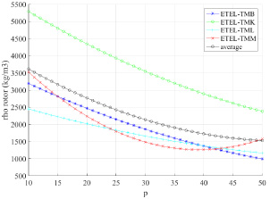
Rotor density of ETEL motors vs. pole pairs number.
The equation of the average curve of the rotor density of the four ETEL types for p > 10 is:
The proposed tool is validated by analyzing the high torque permanent magnet TMB ETEL motors [4]. For each motor, two types of cooling modes are available: free air convection and water cooling. For each cooling mode, the continuous torque and the main sizes of each motor are given in the data sheets.
The number of pole pairs and the continuous torques of the 35 analyzed motors are given according to the two cooling modes (Fig. 3). After adjusting the input data of the assessment tool to ETEL motor data sheets (Table 4), the performances calculated with the tool from these data are compared to the real performances of the motor. The sizes of each part of the motor are calculated by the tool.
For instance, the active length (Fig. 4), the rotor and the external stator radius (Fig. 5) calculated are compared to the values on data sheets. From these sizes, the mass and the specific torque of the motor can be estimated (Fig. 6).
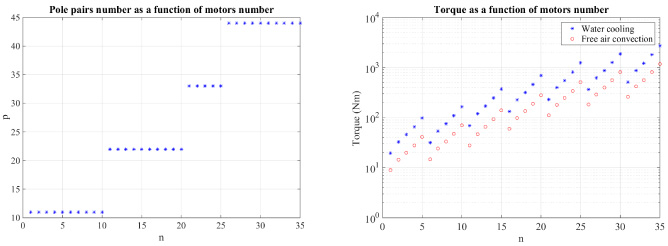
Number of pole pairs and continuous torques extracted from the data sheet of 35 TMB ETEL motors [4].
Input data of the assessment tool suitable for ETEL TMB motors

Comparing the active length calculated to the data sheet of TMB ETEL motors [4].
From Figs 3 to 5, it can be seen that for this type of torque motors, the increase in the torque is done by increasing continuously the length for a given rotor radius and a given number of pole pairs.
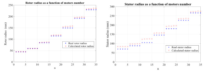
Comparing the rotor and the stator radius calculated to the data sheet of TMB ETEL motors [4].

Comparing the specific torque calculated to the data sheet of TMB ETEL motors [4].
Due to the assumptions made, differences can be observed between the specific torque calculated and the one from the data sheet. Nevertheless one may conclude that the specific torque is calculated with enough accuracy and the variation of the specific torque with motor number follows correctly the variation evaluated from the data sheet (Fig. 6). Only the mass of the active parts are taken into account. That is why the specific torque is so high. Results on Fig. 6 show that water cooling allows to double the specific torque (magnetic shear stress is twice for water cooling than for air cooling).
A tool based on loadability concepts has been developed. By means of some additional balance equations, the tool can quickly size a low speed electric motor. The tool has been evaluated from the data sheet of high torque TMB ETEL motor. The results show that the specific torques are calculated with enough precision to make rapid tradeoffs of high torque electric motors. The loadability concepts seem to be very useful to evaluate the levels of the set of, magnetic, electric and cooling technologies and assess the performance of electric motors. The main advantage of this tool is that it needs very few data: for instance the stator and the rotor are not described completely to make these calculations. The results can then be assessed for many types of electric machines without saliency.
Footnotes
Acknowledgements
This project has received funding from the European Union’s Horizon 2020 (Cleansky 2JTI) research and innovation program, 2014–2024 under grant agreement No 715483.