
Abstract
This paper presents the optimal design of a dual airgap spoke type permanent magnet vernier machine with dual stator dual winding (DDW) and dual stator single winding (DSW) models having an equal outer diameter and the same magnet volumes. The models were compared at a similar power and volume basis. Latin Hypercube Sampling and the Kriging Method is used to optimize the stator slots in DSW models for improved performance. 2D-Finite Element Method (FEM) was used to verify the results and compare the both models. The DSW model performs similar in terms of average torque, back EMF and shows a better performance regarding torque ripple, power factor and core loss as compared to DDW model having same dimensions on similar power and volume basis. Furthermore, DSW model has the advantage of having lesser manufacturing complexity and thermal issue posed by inner stator winding.
Keywords
Introduction
Low-speed, high torque direct drive machines are becoming more popular as compared to their counterpart machines with gearboxes. This is because the former has no problems related to gears such as oil maintenance, noise issues or losses. However, conventional direct-drive machines often show reduced performance due to their large size and low efficiency resulting from the increased number of poles and slots. Therefore, to alleviate this problem, permanent magnet vernier machines (PMVMs) are being increasingly used because of their low speed, high torque performance [1]. PMVMs are designed with a high number of magnet poles compared to conventional PM machines. Furthermore, the number of rotor pole pairs is also different from the number of stator pole pairs. The rotor flux is modulated through a so called “magnetic gearing effect” and able to link the stator and produce a steady torque [2]. Due to its high torque density and direct drive, the vernier machine is a suitable candidate for applications such as robotic arms, industrial applications, and electric vehicles [3,4].
Compared to conventional PM machines, the PMVM has a low power factor. This makes the converter rating of the PMVM large for a given output power, which results in the higher cost and increased volume of the converter. The dual air gap spoke array PMVM was developed to counter this problem and improve the power factor. The spoke array generated high flux density in the airgap through flux focusing in the dual air gap, which in turn results in a decrease in the leakage flux [5–7]. However, dual air gap models have thermal and manufacturing issues in the inner stator winding. A new topology was introduced to overcome these thermal and manufacturing issues, by including an auxiliary inner stator without winding. However, the slot fill factor has not been considered while comparing the dual and single winding models on the basis of equal volume and ampere turns [8]. In [9], the dual winding model was compared with the single winding model on the basis of an equal slot fill factor and outer dimensions, whereas other factors such as the power, torque, and magnet volume were kept different.
In this paper, firstly, a dual stator dual winding model (DDW) vernier machine was designed and the performance was improved following the procedure outlined in [10]. Secondly, a dual stator single winding model (DSW) is designed from the designed DDW model while keeping the same slot fill factor and outer diameter in both models. The comparison of DDW and the DSW models on similar power, torque, magnet volume basis is also presented. As the design of outer slots and inner stator was changed in DSW, the optimization of DSW model was performed to improve its performance. The comparison between DDW and DSW models is presented to show that the optimized DSW model performs similar in terms of average torque, back EMF, and shows a better performance in terms of torque ripple, power factor and core loss as compared to DDW model. Furthermore, DSW does not have any thermal and manufacturing issues posed by the inner stator winding. However, efficiency of DSW model is slightly less than DDW model as only the outer stator has winding and copper loss is increased in DSW.
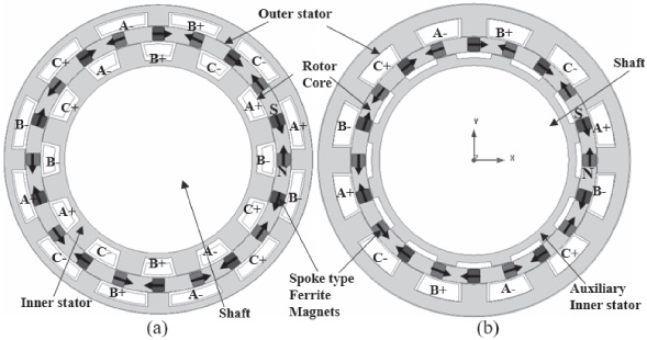
Machine layouts (Basic models). (a) DDW model (b) DSW model.
Design specifications of DDW and DSW models
The machine topologies for the dual and single winding models are shown in Fig. 1 and the design specifications are given in Table 1. In this table, Doi, Dii, Doo and Dio represent the outer stator inner diameter, inner stator inner diameter, outer stator outer diameter, and inner stator outer diameter respectively. Figure 1(a) shows the DDW model with winding on both stators whereas the DSW model with an extended outer stator and an auxiliary inner stator with no winding is shown in Fig. 1(b). The outer stator is extended inwards to accommodate the winding of the inner stator while keeping a similar slot fill factor in both models. Both the models have the same machine volume and same magnet volume, and the comparison was performed using a similar power basis. Both the models use spoke type ferrite permanent magnets that are magnetized circumferentially, and the magnetization directions are inverted alternately. The material used in the rotor and stator cores is steel S50PN470. The load current was less in the DSW model because the winding length is increased in the outer stator and the armature flux will also increase in DSW model. To keep the same armature flux, the current is kept lower in DSW model.
Performance comparison between basic DDW and DSW models
Performance comparison between basic DDW and DSW models
2D-FEM is used to analyze the performance of DDW and DSW models and compare the performance based on equal machine and magnet volumes, and similar torque and volume basis. A comparison was performed for the torque ripple, cogging torque, power factor, efficiency, and torque density. Table 2 shows a comparison of the 2D-FEM results for the DDW and DSW models. The results are explained in the figures and discussed in the following sections.
No load FEA simulation results
Both the models were simulated for load conditions at a speed of 400 rpm. Figure 2 shows the no load flux density plot of DDW and DSW models. The no load flux density was distributed equally on both sides of the rotor in the DDW model whereas the flux density was lower in the inner stator, and the flux is focused outside in the case of the DSW model. Figure 3 shows that the magnitude of the back EMF is less in the case of the DSW model because of the reduced magnet width in the DSW model compared to the DDW model. Figure 4 shows that the cogging torque is higher in the DSW model as compared to the DDW model because of the increased outer stator slot depth in the DSW, model which in turn increased the overall permeance variation in the outer air gap. Table 2 summarized the comparison of the DDW and the basic DSW model.
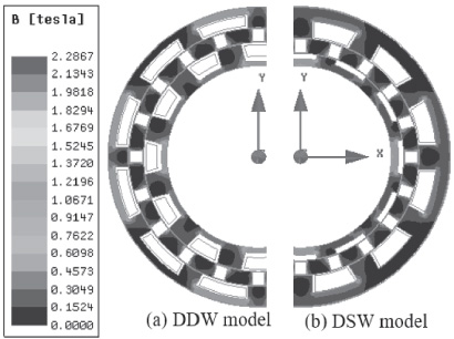
No Load flux density distribution (Basic models).
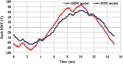
Back EMF comparison (Basic models).
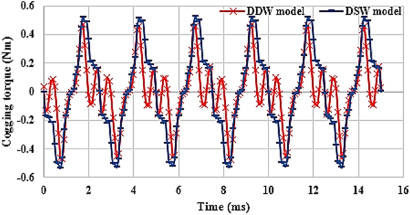
Cogging torque comparison (Basic models).
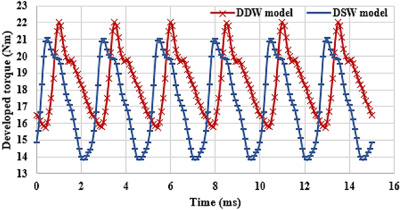
Developed torque comparison (Basic models).
Figure 5 shows the results of the developed torque at a speed of 400 rpm when the current of 4.73 A is applied to the DDW and 4 A was applied to the DSW model for a similar power comparison. This current was used because the winding length was increased in the DSW and so the armature flux was also increased, therefore, to keep it constant, the armature current was reduced. The average torque was slightly reduced in the DSW model. Table 2 also shows that the torque ripple in DSW model is high as compared to the DDW model because of the higher cogging torque in DSW model. Torque per machine volume and torque per magnet volume was also reduced in the basic DSW model compared to the DDW model due to low average torque. The core losses were reduced in the DSW model because of the reduced inner stator core size whereas. The diameter of outer stator is more as compared to the inner stator. When the winding of inner stator is shifted to the outer stator, the overall length of winding is increased due to increased diameter of outer stator. The copper losses are increased due to increased length of turns and hence a decrease in the efficiency of DSW model as compared to DDW model.
As the DDW model was designed properly while DSW was only transformed form it. Therefore, basic DSW is not giving the best performance. The performance of DSW model is improved by using stator slot optimization technique using Latin Hypercube Sampling and Kriging methods [9,11]. The optimized DSW model is compared again with the DDW model for the final results and discussion. The details of the optimization method are discussed in the following section.
Optimization process.
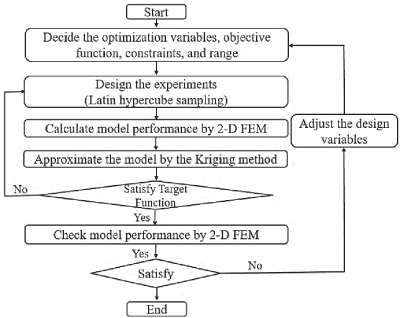
The stator tooth in a vernier machine is considered to be the most important factor to control the flux modulation and therefore to improve the torque generation of the machine [11]. The tooth pitch particularly affects the airgap permeance which in turn affects the flux modulation. Therefore, the inner and outer stator slots were considered as the optimization parameters to improve the average torque, power factor and efficiency in the DDW and DSW models. The optimal design process used in this paper is shown in Fig. 6 [9,11].
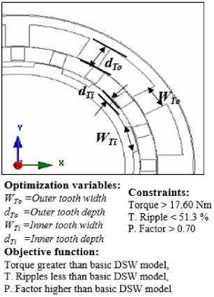
The optimization variables, objective function, constraints and variable limits are defined as shown in Fig. 7. The basic values for the optimization variables are mentioned below:
The range of the optimization variables was selected by a series of simulations and the range was finalized as:
Optimization variables.
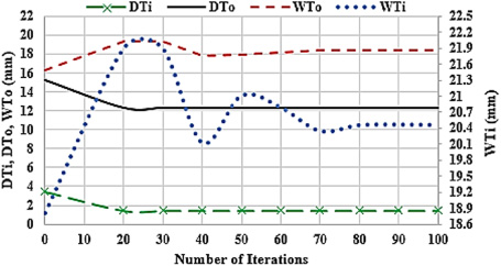
Kriging method was applied to get the approximate values of the optimization variables obtained from Latin hypercube sampling for the required output results. The genetic algorithm is an efficient way of optimization in the design of electromagnetic machines [12]. A genetic algorithm was applied as an optimization method and finite element method was used to analyze the models for the final results. Figure 8 shows the convergence results of optimization variables.
Convergence results of optimization variables.
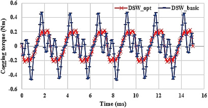
Cogging torque comparison_DSW model.

Developed torque comparison_DSW model.
2D-FEM Results comparison after DSW model optimization
The expected results with the above values of optimization variables are mentioned as below: Cogging Torque = 0.38 Nm, Average Torque = 19.20 Nm, Torque Ripple = 33.2%.
The comparison of the cogging torque and the developed torque between the optimized model and basic model of DSW are presented in Figs 9 and 10 respectively. It shows that the cogging torque was decreased after optimization because of the reduced slot depth in the optimized model which in turn decreased the permeance variation. Back EMF was increased due to the increased flux linkage in the optimized model. The average torque was improved after optimization due to increase in back EMF in the optimized DSW model. Table 3 shows that the torque ripple was decreased from 51.3% to 32.8% in the DSW model after optimization because of the cogging torque reduction in the optimized model. The power factor was also improved from 0.7 to 0.74 in optimized DSW model because of the improved flux linkage in the optimized DSW model. Core loss is slightly increased in the optimized DSW model due to an increase in the core size in the inner stator. The other parameters like torque per machine volume, torque per magnet volume and efficiency are also improved in the optimized model as compared to the basic model of DSW topology.
Comparing the results in the DDW model and optimized DSW model, it is clearly shown in Table 3 that the cogging torque is much lower compared to the DDW model because of the reduced inner stator slot depth in DSW model, as no winding was needed in the inner stator and it is used only as a flux guide. The torque ripple was also lower in the optimized DSW because of the lower cogging torque in the optimized DSW model. The average torque was slightly increased in the optimized DSW as compared to the DDW model due to an improved torque ripple in DSW model. The value of the torque per machine volume and the torque per magnet volume is also slightly improved in the optimized DSW model because of the improved average torque while keeping the same machine and magnet volume in both models. The power factor of the optimized DSW model is almost similar with the DDW model because of the similar electric loading in the both models. Core loss is also less in the optimized DSW model as compared to the DDW model. Considering all the above parameters, it can be clearly said that the optimized DSW model performs slightly better in terms of average torque, power factor and shows improvement in terms of torque ripple and core loss as compared to the DDW model on equal outer dimensions, similar power, and same magnet volume basis. The DSW model also has advantages over the DDW model in terms of reduced thermal and manufacturing problems because of the absence of inner stator winding as compared to the DDW model. The only drawback is that the copper loss is increased in the DSW model because of an increase in the winding length in the outer stator. This increase in copper losses reduced the efficiency of DSW model slightly. So, overall, it can be concluded that the small reduction in efficiency can be better tradeoff for slight performance improvement and reduced manufacturing cost and complexity.
The two different topologies of dual airgap spoke type PMVM are discussed in this paper. The stator slots optimization in DSW model resulted in improved performance similar in terms of average torque, back EMF and shows a better performance regarding torque ripple, power factor and core loss as compared to DDW model. However, there is a slight reduced efficiency in the DSW model due to increased winding length in the outer stator which causes and increase in copper losses as compared to the DDW model. So, this small reduction in efficiency can be considered a tradeoff for the improvement in performance along with the reduced thermal and manufacturing problems due to the absence of inner stator winding.
Footnotes
Acknowledgements
This work was supported in part by the BK21PLUS Program through the National Research Foundation of Korea within the Ministry of Education, and in part by the National Research Foundation of Korea (NRF) grant funded by the Korea government (Ministry of Science) (No.NRF-2017R1A2B4007697).