
Abstract
A multi-purpose module system (MMS), a modular robot, comprises joint and function modules. This robot can be variously configured to form serially connected and quadruped robots. This study presents initial designs and tests for a new locomotion module that uses Mecanum wheels (WM11-01). The WM11-01 comprises two Mecanum wheels on a single rotating shaft. Using this locomotion module, MMS-V01-Wn is proposed. In addition, physical specifications for the robot and equations for its locomotion control scheme are developed. These equations deliver relative rotational speeds of the Mecanum wheels that should generate robot motion in any direction. The WM11-01, at a diameter of only 100 mm, can move through particularly narrow pipes and channel-shaped terrain. We tested the MMS-V01-W1 in a pipe and found that roughness in the pipe surface did not significantly affect the robot’s locomotion. The results below demonstrate the adaptability and effectiveness of a miniaturized omnidirectional locomotion module.
Introduction
Disaster-affected areas present various terrain scenarios such as heaps of rubble and collapsed, submerged, and burned-out vehicles and houses. These environments are scattered over a large area. At present, several distinct rescue robots are typically employed in disaster response because they have been purpose-built for specific terrains [1–6]. For example, a wheeled robot is capable of very fast movement on smooth surfaces but not on irregular terrains. A crawler robot has good mobility on irregular terrains but not on uneven grounds. A legged robot has good mobility on irregular terrains, uneven grounds, and stairs, but it is slower and consumes more energy than the wheeled and the crawler robots.
If rescuers are familiar with the terrain at the disaster site, they can select an appropriate robot. However, not all rescue teams can be familiar with all disaster zones. Furthermore, a large inventory of terrain-specific robots is difficult to acquire and store owing to high costs, lack of storage space, transportation issues, and lack of trained personnel with robot operation expertise. To respond to this issue in the disaster-robot market, we develop modular robot that can respond to a range of terrain and disaster scenarios. In past few decades, the literature on modular robots has flourished, and numerous robot development and control approaches have been proposed [7,8]. However, these modular robots often only include joint modules, thus limiting their applications.
Therefore, we propose a multi-purpose module system (MMS) that includes both joint and function modules. This MMS can be variously configured, including series-connected and quadruped modes. This is an advantage for situations in which terrain information is not available before deployment because the MMS can morph into an appropriate form based on sensor data on inspecting a site. Thus far, we have developed several modules for the MMS: joint, sensor, communication, divergence, and toe modules. In addition, several MMS configurations such as a series-connected MMS using joint modules (model MMS-C02) and quadruped MMS (model MMS-G03) have been proposed and evaluated [9,10].
In this study, a new type of module using Mecanum wheels (WM11-01) is developed. WM11-01 has two Mecanum wheels on a single rotating shaft. Therefore, the WM11-01 can move the robot without turning by varying wheel rotational speeds and directions, as explained. A wheeled MMS configuration using the WM11-01 module (MMS-V01-W1) is also detailed. We finally evaluate the locomotion performance of this configuration and a robot with two WM11-01 modules under a range of conditions.
Omnidirectional wheel module specifications
First, specifications for each component in the WM11-01 locomotion module are provided. A schematic of the WM11-01 is shown in Fig. 1. The WM11-01 is 0.100 m in diameter and 0.397 m long, and its weight is 1.65 kg. The WM11-01 module comprises two Mecanum wheels on a single rotating shaft, two DC motors with gears and encoders, a microcomputer for control, and a battery with a charging circuit.
Connectors are included on either side of the module. Modules easily connect with a simple push-button catch. Electrical connections are also included in the connector and are ensured with a spring-loaded mechanism.
Each Mecanum wheel has nine free rollers with an axis of rotation at ±45° to the wheel axis. Therefore, the WM11-01 is able to move in any direction at high speed by varying wheel rotational speeds and directions without changing the robot shape. Assuming the DC motor comprises a resistor, a coil, a capacitor, and a counter-electromotive force, the relation between rotational speed and applied voltage can be calculated using an equivalent circuit. Proportional control is selected to control the speed via varying the applied voltage.
The WM11-01 has contact surface around its entire circumference and can move through spaces only as small as the robot diameter of 0.100 m. The WM11-01 can therefore move through narrow spaces and rough terrain such as pipes or channels.
A wheeled MMS configuration using the WM11-01 module (MMS-V01-W1) was also designed. A photograph of the MMS-V01-W1 robot is shown in Fig. 2. MMS-V01-W1 comprises three modules: a functional module (TC01-01) with a camera, a WM11-01 for locomotion, and a communication module (CB10-02) for control and communication. The camera module is attached at one end of the robot. The TC01-01 mounts a camera for robotic vision. The CB10-02 is the main module that issues orders to the rest of the robot. This module communicates not only with other modules, but also a personal computer and controller for remote control. Each module is 0.070 m in diameter. The overall dimensions of the MMS-V01-W1 robot are as follows: 0.100 m in wheel diameter and 0.605 m long; it weighs 2.05 kg. The wheel rotational speeds are controlled via an on-board microcomputer.
Motion control method
Until now, various robot with Mecanum wheels had been proposed [11–14]. Mostly these robots are vehicle with quadrangular arrangement of four wheels. In the proposed robot, the arrangement of the wheels changes according to the combination of the modules.

A schematic of WM11-01.

A photograph of MMS-V01-W1.
The motion of the entire robot is determined by the rotation speed of each Mecanum wheel. The rollers at 45° along each Mecanum wheel translate the two rotational motions of the wheels into robot’s motion. Therefore, the robot’s motion is calculated by the vector synthesis of the velocity vectors of each Mecanum wheel.
Equation (1) gives the direction and velocity of the MMS-V01-W1 robot in terms of the rotational speed of each of its two Mecanum wheels.
In Eq. (1),
The WM11-01 module can also be used in pairs. A similar MMS configuration, the MMS-V01-W2, has two WM11-01 modules. This robot’s motion is governed by Eq. (2).
In Eq. (2),
In this paper, since the robot form varies with the combination and the number of modules, it is not practical to implement control of the entire robot in each module corresponding to various forms. Therefore, the control of rotational speeds uses PID control individually in the module.
With the Eq. (1) in Section 3, the relation between wheel rotational speeds and moving direction for the WM11-01 can be plotted, as shown in Fig. 3. The simulation conditions are r = 0.05 m, l = 0.055 m, and v = 0.250 m/s. The wheel rotational speed changes sinusoidally with the direction of MMS-V01-W1. These calculations indicate that the MMS-V01-W1 can move in any direction by merely changing the relative rotational speeds of the two wheels.
The locomotion performance of the MMS-V01-W1 robot was evaluated by experiment. The experimental conditions were the same as the simulation conditions. The MMS-V01-W1 moved on a flat floor, as pictured in Fig. 4. A typical trajectory of the MMS-V01-W1 at a direction of 0° is shown in Fig. 5.
The MMS-V01-W1 began its motion at the origin of the pictured coordinate axis and the direction of 0° was aligned with the y-axis in Fig. 5. This test showed that the MMS-V01-W1 moved roughly in a straight line but it slightly turned.

Relation between rotational speed and direction of MMS-V01-W1.
Trajectories for various directions are shown in Fig. 6. In Fig. 6, the MMS-V01-W1 starts moving from the origin and is directed in the target direction. These tests indicated that the MMS-V01-W1 could move in any direction without turning, in roughly a straight line. The average error from straight-line locomotion was 1.7°. The slight trajectory error occurred because of an uncertainty in the rotational velocity supplied by the electric motors, a slightly unbalanced center of mass, and friction differences along the contact areas of the wheel rollers. The rotational speeds for each Mecanum wheel in this test are shown in Fig. 7. The rotational speeds are slightly different because each wheel is controlled individually. In addition, friction between the wheel and floor varies as the free rollers on the wheel make contact. Motions in the 90° and 270° directions are more stable than motions in other directions because the rollers are in-line with the direction of travel. In addition, the robot is also balanced around the rotational axis when traveling in this direction.

A photograph of experimental situation at 0°.

Typical trajectory of MSS-V01-W1 at 0°.

Trajectories for motions at various angles to the MMS-V01-W1’s centerline.

Actual wheel rotational speeds for two directions of travel of the MMS-V01-W1.
The robot vibrated when moving in all directions due to the free rollers. Modular robots require robust connections between the modules. Vibrations caused by the wheel module may interrupt the spring-loaded electrical contacts in our quick-release connectors. Therefore, improved connectors with a magnetic clasp may be necessary for use with the WM11-01 module.
The MMS-V01-W1 robot was designed for moving through narrow spaces with rough surfaces. Thus, one of the applications is moving inside the pipe for inspection. We tested this case with the apparatus pictured in Fig. 8. The test pipes were made of polyvinyl chloride with interior diameters of 0.114, 0.140, and 0.165 m. These are the dimensions for standard drain pipes in Japan. We kept the DC-motor input voltages constant to understand the effect of pipe diameter on the robot’s motion. Typical characteristics of robot’s moving velocity are shown in Fig. 9. The results indicated that the MMS-V01-W1 properly moved through the pipes as good as it did on a flat floor. These tests showed that the pipe diameter has negligible effects on the robot’s velocity, confirming that the robot can move through uneven terrains.

A photograph of experimental situation in the pipe.

Typical characteristics of moving velocity.
Similarly, the locomotion performance of the MMS-V01-W2 configuration was evaluated. Trajectories of MMS-V01-W1 and MMS-V01-W2 are shown in Fig. 10. The conditions are the same as the simulation conditions. The average error from straight-line locomotion of MMS-V01-W2 was 0.7°. The MMS-V01-W2 was found to be more stable than the MMS-V01-W1. Locomotion efficiency is therefore improved with four Mecanum wheels. It is possible that the MMS-V01-W2 can turn on the spot. Trajectory of MMS- V01-W2 at condition of v = 0 m/s, and
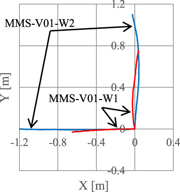
Trajectories of MMS-V0-W1 and MMS-V01-W2.
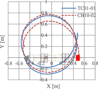
Trajectory of MSS-V01-W2 at turning motion.
In this study, a WM11-01 locomotion module using Mecanum wheels is proposed, and its unique locomotion strategy is evaluated.
The WM11-01 module has two Mecanum wheels on a single rotating shaft. Therefore, via varying the rotational speeds of each Mecanum wheel, the WM11-01 is able to move in any direction without turning the robot itself. With only two Mecanum wheels, the WM11-01 can afford high-speed locomotion through narrow spaces. An equivalent circuit was used to translate applied DC-motor voltage to rotational speeds; further, a proportional voltage controller was implemented to vary wheel speeds.
A modular robot configuration with a single WM11-01 module, the MMS-V01-W1, was tested, and wheel speeds for each direction of motion were selected according to a set of differential equations that describe motion driven by Mecanum wheels. The straight-line locomotion efficiency of the MMS-V01-W1 robot evaluated in several conditions. The MMS-V01-W1 robot can move in any direction at a speed of 0.250 m/s. The average error from straight-line motion was 1.7°. The motions in-line with the cylindrical robot’s centerline are more stable than motions oriented perpendicular to the centerline. For locomotion in this direction, the WM11-01 module has a distinct advantage in moving through curved channels or pipes. The fact that the MMS-V01-W1 could move through a pipe of varying diameter with little deterioration in speed was also verified.
It is possible that the MMS-V01-W2 can turn on the spot. Moreover, the MMS-V01-Wn configuration with several WM11-01 and joint modules dramatically improves the locomotion efficiency.
In future work, the proposed mechanical and magnetic connector will be installed and experimentally evaluated under various conditions.
Footnotes
Acknowledgements
This work was supported by JSPS KAKENHI Grant Number JP17K06279.