



Abstract
In high-speed scanning MFL inspection for a steel pipe, according to Lenz’s Law, motion-induced eddy current (MIEC) is induced by relative movement between axial magnetizer and the inspected pipe. On the one hand, magnetic field generated by MIEC will change the magnetization intensity of the pipe and thereafter change the signal amplitude; on the other hand, it will also cause signal baseline shift by altering background magnetic field. In this paper, the effect of MIEC on axial MFL inspection is investigated by theoretical analysis, finite element simulations, and high-speed experiments. It is found that at different locations MIEC causes different change trends for both the background magnetic field and magnetization intensity, leading to sensitivity difference, which should be taken into consideration in the high-speed MFL inspection for a steel pipe.
Keywords
Introduction
As a powerful and efficient nondestructive testing method, magnetic flux leakage (MFL) testing has been widely applied for inspection and evaluation of ferromagnetic materials, especially suitable for high-speed scanning inspection, such as the railway, steel rope and pipeline [1–11]. According to the Lenz’s Law, the relative movement between the magnetizer and inductive specimen will induce eddy current in the specimen, i.e., motion-induced eddy current (MIEC) [12,13]. And of course, the MIEC itself will also induce magnetic field and thereafter change the magnetization intensity of the specimen. It is known that testing signal depends on magnetization status of the specimen hence the MIEC will alter MFL signal characteristics, resulting in sensitivity difference among the defects of same size but under variable inspection speeds. Particularly, when the MFL scanning inspection is performed at a high speed, the MIEC will change MFL signal characteristics greatly.
Up to now, there are many papers to investigate the effect of the MIEC on the MFL testing. Since there is high cost and also high risk to perform high-speed MFL experiments, FEM simulation is the first choice to study the MIEC. At the beginning, YK Shin built numerical modeling of the MIEC and then investigated MFL signal amplitude at different testing speeds [14,15]. Then, Yong Li investigated the MIEC by commercial software ANSOFT Maxwell EM. It was found that the MIEC will not only distort the profile of magnetic field but also decrease the intensity of magnetic field. A defect generates two value peaks around the edge of the defect with different amplitudes. Besides, when the testing speed increases, the signal magnitude drops [16].
The discussed-above researches are about the internal MFL inspection, in which the detection device is placed inside the pipeline. Another application of MFL testing is external detection that the pipe passes inside the detection device. Jianbo Wu investigated MIEC effect on the axial magnetization for circumferential defect and built the elimination method for the sensitivity difference between the pipe body and tails by simulation and experimental studies with maximum speed of 2.5 m/s [17,18]. Zhiye Du investigated high-speed MFL inspection by both simulation and experiment with speed of 5.0 m/s [19]. Then, Jianbo Wu and JI Etcheverry investigated the influence of MIEC on circumferential magnetization for longitudinal defects for steel pipes at different speeds by experimental studies [20,21]. Ping Wang investigated the high-speed MFL inspection for railway by experimental studies at different speeds up to 55 m/s. It was found that the testing MFL amplitude will increase with the increase of testing speeds due to the dynamic magnetization [22].
In fact, the MIEC influences MFL signal characteristics in two ways: (1) the MIEC will induce magnetic field and thereafter alter the magnetization status of steel pipes, which will change detection signal amplitude. In practical MFL application, in order to accomplish 100% coverage for steel pipes, sensor array is usually arranged to form a large inspection area. Since the MIEC-induced magnetic field in the detection area is non-uniform, the defects of same size but inspected by different-located sensors will generate different signal amplitudes, which has been overlooked in previous studies; (2) the picked-up magnetic field by sensors actually consists of three components: the initial background magnetic field, the background magnetic field generated by the MIEC and the leaked magnetic field generated by the defects. The MIEC-induced background magnetic field also has been ignored in earlier researches.
Due to the development of high-speed continuous-rolling pipe mills, high-speed scanning MFL testing for steel pipes is increasingly in demand. In this paper, in order to improve the axial MFL inspection for steel pipes, the effect of the MIEC on axial MFL inspection is investigated. Firstly, the distribution of MIEC-induced magnetic field is theoretically analyzed; then, finite element simulations are conducted to investigate the magnetization status and background magnetic field at different scanning speeds; finally, high-speed MFL experiments are performed to investigate the MFL signal characteristics, in which MFL testing for a rotating steel plate is used to simulate the linearlymoving steel pipe to achieve variable high scanning speeds.
Theoretical analysis of the effect of MIEC on axial MFL inspection for a steel pipe
The axial MFL inspection for steel pipes is usually conducted by an insert coil. The direct current flowing in the insert coil generates an axially-orientated magnetic field, as depicted in Fig. 1(a). Along the pipe moving direction, the steel pipe is divided into two parts from the center of coil: the arriving zone and the leaving zone. In the arriving zone, the magnetic field generated by the coil enters into the pipe from the air and then go back into the air in the leaving zone.
Based on Lenz’s Law, MIEC density j(r
0, z
0) in the circle l(r
0, z
0) in the pipe is expressed as follow [11,12]:
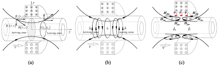
The magnetic field distributions generated MIEC. (a) The diagram of axial MFL inspection for a steel pipe; (b) the distribution of MIECs in arriving zone and leaving zone; (c) the distribution of MIEC-induced magnetic field.
In practical MFL application, in order to accomplish 100% coverage for steel pipes, sensor array is usually arranged to form a large scanning area. Sensors P1, P2 and P3 indicate possible arrangement at different axial locations, respectively. Based on vector superposition principle, the picked-up magnetic field H
t
by the sensors is composed of three components: magnetic flux leakage H
mfl
generated by defects, the initial background magnetic field H
ibk
and the MIEC-induced background magnetic field H
jbk
:
The signal baseline difference among the three sensors discussed-above is caused by the background magnetic field changes at the sensor locations. Further, MIEC will also cause H
mfl
difference among the defects of same size at different locations. The total magnetizing field H
m
in the steel pipe consists of the initial magnetizing field H
im
generated by the magnetizer and the magnetizing field H
jm
caused by MIEC, as follows:
To sum up, due to the MIEC, the defects of the same size but at different locations will generate different signal characteristics, including the baseline and the amplitudes
In order to confirm the magnetization status and background magnetic field at different scanning speeds, numerical simulations considering the moving components are conducted in this paper using ANSOFT Maxwell EM, which is suitable for frequency and time-domain electro-magnetic fields in complex structures [20]. As illustrated in Fig. 2(a), the simulation model shows the cross-section of the excitation coil and steel pipe. The thickness, inside and outside diameters of the coil are 100 mm, 220 mm and 420 mm, respectively; the excitation direct current density is 2.0 ×10⁶ A/m2; the length, outside diameter and thickness of the steel pipe are 3000 mm, 180 mm and 10 mm, respectively; the steel grade of the pipe is 45 (conductivity: 2 ×10⁶ S/m, having B-H curve). In simulations, the steel pipe moves from the left side of the excitation coil and halts at the right edge at specified speeds of 1.0 m/s, 10.0 m/s and 100.0 m/s, respectively. When steel pipe reaches the center of the excitation coil at the speed of 1.0 m/s, the contour of the eddy-current in the pipe is obtained, as displayed in Fig. 2(b). It can be seen that MIECs with opposite directions are induced in the arriving zone and leaving zone. Further, the background magnetic field and magnetization intensity are simulated and picked up at different scanning speeds of 0 m/s, 1.0 m/s, 10.0 m/s and 100.0 m/s, as displayed in Fig. 2(c) and (d). With the increase of the scanning speed, the background magnetic field increases in the arriving zone while it decreases in the leaving zone. On the contrary, magnetization intensity of the pipe in the arriving zone is weakened while it is enhanced in the leaving zone at high scanning speed. It can be concluded that at different scanning speeds, the background magnetic field and magnetization intensity both present different change trends at different locations, which match the theoretical analysis well.

Numerical simulation of MIEC effect. (a) The simulation model for the MIEC; (b) The contour of the MIEC at the speed of 1.0 m/s; (c) the background magnetic field along L 1 at different scanning speeds; (d) the magnetization intensity of the pipe along L 2 at different scanning speeds.
To validate the effect of MIEC on axial MFL testing, high-speed experiments are performed in laboratory condition. To avoid the high cost and high risk in the linearly-moving experiment, a high-speed rotary moving experimental platform is built to simulate the steel pipe inspection, which can easily conduct the high-speed experiment and control the speeds. As displayed in Fig. 3(a), a circular steel plate is driven by a motor to rotate anticlockwise. The rotating steel plate (diameter: 800 mm, thickness: 10 mm) with an artificial defect (length: 25.0 mm, width: 1.0 mm, depth: 1.0 mm) is magnetized by an axial magnetizer, which consists of two hollow cylinder permanent magnets and a magnetic yoke. Both the magnets and yoke have an open mouth to permit the plate rotate inside and magnetize it axially. Three hall sensors P1, P2 and P3 are placed in the arriving zone, the center and the leaving zone, respectively. When the plate rotates, the defect will be scanned by the three sensors, respectively. The high-speed rotating platform is pictured in Fig. 3(b). In order to ensure the safety of the experiment, a safety cover and an aluminum clamp plate are used to avoid mechanical components and steel plate flying out.
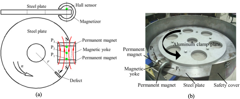
The high-speed MFL testing experimental setup.
With the rotating speed gradually increasing from 0 to 600 rpm, the defect is scanned by the three hall sensors P1, P2 and P3 at an increasing speed, as displayed in Figs 4(a), (b) and (c), respectively. It can be seen that with the testing speed increasing, the signal characteristics picked up by the three sensors have different change trends. The signal baseline of P1 gradually increases while that of P3 decreases. On the other hand, with rotating speed increasing, the MFL signal amplitude picked by P1 drops while that of P3 increases. Besides, the signal characteristic of P2 has the same change trend as that of P1 but with a smaller change rate. All the experiment results are accordant with the theoretical analysis and simulation results.

The testing signals picked up by hall sensors with an increasing testing speed. (a) The testing signal picked up by P1; (b) the testing signal picked up by P2; (c) the testing signal picked up by P3.
In order to improve the axial MFL inspection for steel pipes, the effect of the MIEC on axial MFL inspection is investigated in this paper by theoretical analysis, finite element simulations, and high-speed experiments. It can be concluded that on the one hand the MIEC-induced magnetic field will change the background magnetic field, causing different signal baseline shifts in the arriving zone and leaving zone; on the other hand, it will also cause different the magnetization intensities of steel pipes in the arriving zone and the leaving zone and thereafter lead to different detection signal amplitudes. Because of these influences, in practical MFL application, the MIEC will cause sensitivity difference among the sensors at different locations. In order to promote the accuracy of the MFL testing for steel pipes, firstly, the high-pass filtering method could be used to eliminate the baseline shift. Besides, for a fixed testing speed, the MFL signal amplitude difference among the sensors at different locations are certain thus it could be eliminated by using calibration method.
Footnotes
Acknowledgements
This work was financially supported by National Natural Science Foundation of China (Grant No. 51505308), and Technology support program of Sichuan Province (Grant No. 2018JY0393).