



Abstract
To optimise the working performance of magnetorheological damper, a new parallel gap magnetorheological damper is designed. The validity of the structural design is verified and guided by establishing a mathematical model of a parallel gap magnetorheological damper. The damper is designed using a check valve structure, which greatly reduces the installation space, reduces the transfer linkage, and improves the reliability of the damper. The newly-designed damper has many advantages, such as high efficiency, high sensitivity, no precipitation, good heat dissipation, greater damping force, and so on. The experimental and theoretical analysis results show that the performance of the parallel gap magnetorheological damper is excellent.
Introduction
A magnetorheological (MR) damper is a damping element that utilises the MR effects of MR fluids. When exposed to a magnetic field, the rheology of the MR fluids reversibly and instantaneously changes from a free-flowing liquid to a semi-solid with a controllable yield strength [1]. Its flow characteristics will change with changes in the applied magnetic field, so as to realise adjustment of the damping coefficient. Importantly, the yield stress of the fluid when in its active (“on”) state can be controlled by varying the magnetic field intensity [2].
The MR damper is an attractive candidate in vibration suppression applications in which only a small amount of energising power is required and the fluid characteristic is reversible within millisecond time intervals. The advantages include: fail-safe status, low-power consumption, force controllability, rapid response (within milliseconds), good adaptability, and it can be easily combined with a computer system to permit intelligent control [3]. To date, MR dampers have a place in the automotive industry including use in off-road vehicles, and they are also widely used in naval gun control, aircraft landing gear, high-speed train suspensions, for seismic vibration control of different civil structures [4–7], and so on.
An MR damper is one of the most advanced devices used in a semi-active control system to mitigate unwanted vibration because the damping force can be controlled by changing the viscosity of the internal MR fluids [8]. Currently, the structure of the MR dampers presented in the literature adopts a damping cylinder-piston structure, and a rotating structure is used in some special occasions. They all make use of the principle that, when an MR fluid flows through the cylinder annular gap [9–11], a pressure difference is generated, to make the damper produce a damping force. The current problem in damper design is the contradictions between the damping force and heat dissipation, as well as that between installation conditions of the chassis and the damper volume. Here, we propose a new type of MR damper with a parallel gap to overcome the problem of low magnetic field efficiency of MR dampers for piston structures.
Design program for an MR damper
Given the limited mounting space of most special automobile chassis, the volume of the damper should be small [12]; but the chassis requires a large damping force and the overheating is not allowed. Given this limitation of the installation space of the chassis, the damper can only be of a single rod type. To make the coil cooler it can be considered from two aspects: one is to improve the efficiency of the magnetic field and the other is to use the external structure. Obviously, the annular gap flow MR damper cannot meet the requirements of application. So we propose a parallel-gap hybrid MR damper.
Structural design of the parallel-gap MR damper
In the program demonstration stage, we established a mathematical model of the parallel-gap MR damper [13]. The relation between the fluid pressure gradient and the radius of the disk in the single disk gap and the relation between the core flow area and the radius of the disk were obtained by the model, which guided the structural design of the MR damper.
Principle analysis of the parallel gap MR damper
The prototype is designed as a sole-ended external valve mode damper. The most prominent feature is that the damping force is established on the basis of the parallel disk gap flow mode.
The damper (Fig. 1 is its schematic) is designed as a double-cylinder air-compensation structure, which mainly comprises a damping cylinder (1), a damping generator (2), two piston check valves (3), a bottom cavity check valve (4), and a liquid storage tank (5). The damping generator comprises coils, a coil frame, and a plurality of discs. The damping cylinder comprises a cylinder body and piston. The magnetic field intensity can be changed by varying the coil current. When subjected to a magnetic field, the flow characteristics of the MR fluid are changed: the pressure difference between the upper and lower cavities of the damping cylinder is generated, which is the main source of the damping force of the MR damper. The prototype is characterised by the check valve in the piston and the bottom cavity check valve at the bottom of the big cavity (blue area in Fig. 1, and the rod cavity (yellow area) on the right side of the damping cylinder is called the “small cavity”).

Schematic configuration of the parallel gap MR damper.
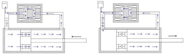
The direction of ferrofluid flows at each phase.
When the piston is stretched (Fig. 2 shows the direction of ferrofluid flows at each phase), two piston check valves (3) are closed and the bottom cavity check valve (4) is opened. The MR fluid in the small cavity flows through the loop pipe into the damping generator, and then into the big cavity, generating a controllable damping force. Meanwhile, there is the volume difference between the big cavity and the small cavity when in motion. The MR fluid in the liquid storage tank flows through the rehydration pipeline into the big cavity under the pressure generated, which solves the problem of the volume difference between the two. The volume difference between the big cavity and the piston rod determines the magnitude of the damping force under an applied current.
When the piston is compressed, two piston check valves (3) are opened and the bottom cavity check valve (4) is closed. The MR fluid in the big cavity flows through the piston into the small cavity. Meanwhile, there are the surplus MR fluids because of the volume difference between them. The surplus MR fluid flows through the loop pipe into the damping generator to produce a compression controllable damping force and then returns to the liquid-storage tank. The diameter of the piston rod determines the magnitude of the compressive damping force under the applied current.
During the entire stroke, it can be seen that the flow direction of the MR fluid in the cylinder is the same; that is, it keeps flowing from left to right. This ensures that there is no idle stroke during the movement, and the pressure-displacement diagram is full. It is clear that proper structural parameters would ensure that the compression force of the prototype would be less than the stretching damping force. Overall, the prototype has the following characteristics:
High efficiency, high sensitivity, coil-less heating, and a relatively small applied current. Good heat dissipation. The damping generator and the liquid storage tank of the prototype are both outside the damping cylinder. The cylinder has a single-layer structure, so offering good heat dissipation. The coil of the prototype is not subjected to high pressures and temperatures because it is outside the damping cylinder. This should give it a long service life. The MR fluid in the upper and lower cavities of the damping cylinder is forced to flow, and does not easily produce metal powder precipitation. It is also convenient to add MR fluid. The control wiring layout is simple. The prototype has a simple structure, a small volume, a low cost, and easy maintenance. The damping generator and the liquid storage tank of the prototype are both outside the damping cylinder, and the radial and axial dimensions of the damper are much smaller, leading to convenient maintenance and adjustment. Meanwhile, the position of the damping generator and the liquid storage tank is flexible and easy to configure, and the control wire is easy to arrange.
When we designed the MR damping generator, the following factors were considered [14]:
The direction of the magnetic field lines should be perpendicular to the flow direction of the MR fluid. The magnetic core material must have high permeability. The resistance of the coil should be as low as possible, and the gap should be chosen to be as small as possible. There should be no abrasive particles in the MR fluid, to reduce the wear of the moving parts of the damper. The MR fluid should be compatible with the sealing elements, the working elements, and so on, to prevent corrosion. Proper sealing should ensure no leakage.

Schematic configuration of the parallel gap MR damper.
Figure 3 is a schematic diagram of the damping generator. The damping force is established based on the parallel disk gap flow mode. The damping generator primarily comprises a coil (1 in Fig. 3), an outer cylinder (2), a circumferential hole disk (3), and a center hole disk (4). The gap between the central hole disk and the circumferential hole disk forms an MR fluid channel. The MR fluid flows into port A and out of port B in the direction of the arrow.
The magnetic field intensity can be changed by varying the coil current. When subjected to a magnetic field, the flow characteristics of the MR fluid are changed: the pressure difference between the left and right ports of the damping generator is generated. The damping generator is an important component in the production of the damping force.
The structural design of the damping generator is based on the principle by which flow between parallel disks generates a pressure difference. The controllable damping force is mainly generated by the gap between the disks. When the flow direction of the MR fluid is perpendicular to the magnetic flux direction, the maximum damping force can be produced. The damping force can be obtained by Eq. (1):
Numerical analysis shows that the size of the disc gap, the inlet diameter of the disk and the orifice diameter of the disk exert a significant influence on the pressure difference between the ports. The characteristics of the MR damper can obviously be changed by adjusting the number of parallel disks and the size of the gap.
It is necessary to ensure that the damping generator has a high enough magnetic field intensity: the magnetic circuit design of the damping generator directly affects the range of the controllable damping force. The magnetic circuit structure of the damping generator is shown in Fig. 3. The magnetic circuit comprises the MR fluid in the gap, the parallel discs, the upper and lower end covers, the inner cylinder, and the outer cylinder. Simulation analysis of each component of each different material was done to determine the most appropriate material to be used for each component.
Finally, the upper and lower ends covers, the outer cylinder are made of low carbon steel, the inner cylinder is made of magnetic isolating material, and the inner cylinder and the outer cylinder are coils. The current density in the coil is 3 Amm−2, and the inner cylinder is filled with MR fluid. The relative permeability of the low-carbon steel is 1600, the relative permeability of the MR fluid is 4, and the relative permeability of the coil is 1.
The task of the magnetic circuit design is to determine the necessary ampere-turns (NI) for the magnetic circuit. The optimal design of the magnetic circuit requires the maximisation of the magnetic field energy in the fluid gap, and minimisation of the energy loss in the steel guide and the non-working region. The total amount of steel in the magnetic circuit also needs to be minimised. The magnetic circuit of the damping generator is shown in Fig. 4. The upper and lower ends cover and the outer cylinder of the damping generator are made of low carbon steel, which has high magnetic permeability conductivity and magnetic saturation characteristics, and guides and concentrates magnetic flux into the fluid gap as a magnetic channel guide.
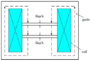
Magnetic circuit structure of the damping generator.
It is necessary to know the magnetic field intensity in each part when determining the ampere-turns rating of the coil. According to the design of the prototype, it is assumed that the specific dimensions are as follows:
The gap h is 3 mm, the inflow radius of the disc r 1 is 4 mm, the outflow radius r 2 is 20 mm, the outer cylinder inner radius R1 is 40 mm, the outer radius R2 is 50 mm, and the length is 100 mm.
Figure 5 shows the relationship between the yield stress and the magnetic field strength of MR fluid. Figure 6 shows the relationship between the magnetic induction and the magnetic field strength of the MR fluid. Figure 7 shows the relationship between the magnetic induction strength and the magnetic field strength of the low-carbon steel.
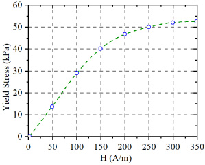
The relationship between the yield stress and the magnetic field strength of the MR fluid.

The relationship between magnetic induction and the magnetic field strength of the MR fluid.

The relationship between the magnetic induction strength and the magnetic field strength of the low-carbon steel.
The steps for determining the number of ampere-turns of the magnetic circuit are as follows:
The expected yield stress τ0 = 54. 6 kPa, the magnetic field strength in the MR fluid is determined from shown in Fig. 5 to be H
f
= 350. 0 kA∕m. The magnetic induction intensity of the MR fluid is shown in Fig. 6 to be B
f
= 1.005 T. The effective magnetic flux area of the MR fluid channel is A
f
= πr
2
2 = 1256 mm2. The effective magnetic flux area of the outer cylinder is A
s
= π(R
2
2 − R
1
2) = 1492 mm2. The magnetic induction intensity of the low-carbon steel is B
s
= 0.8460 T. The magnetic field strength in the low-carbon steel is shown in Fig. 7 to be H
s
= 0.4065 kA/m. The length of gap g = 2h = 6 mm; the steel path-length is L = 294 mm. Therefore, the required ampere-turns rating is: NI = H
f
g + H
s
L = 2220 A.
Therefore, if the design coil was 1000 turns, the maximum current is only 2.22 A, which meets requirements.
The whole structure of the MR damper comprises a damping generator, a cylinder body, a piston, a piston rod, a fluid supply device, etc. Dampers are designed as a double-cylinder air compensation structure, the damping cylinder and the damping generator of the prototype were a one-piece structure, which greatly reduces the installation space, reduces the transfer linkage, and improves the reliability of the damper.
The physical dimensions of each component should be matched, and the total damping force which includes the controllable damping force and frictional damping force, should be taken into account. Here, theoretical calculation and experimental verification are carried out: if the control system fails, or the MR fluid loses its MR effect, the MR damper can be used as an ordinary shock absorber in practice.
Figure 8 shows the damping generator, the prototype, and the discs.
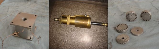
The damping generator, the prototype, and discs.
Based on the structural principle underpinning the behaviour of the MR damper prototype, the compression damping force and the stretching damping force of the damper are analysed as follows: suppose that the inner radius of the damping cylinder is R, the outer radius of the piston rod is r, and suppose that the damping generator produces the same pressure difference P during stretching and compression, for prototype, the compression damping force is:
The stretching damping force is given by:
It is obvious that the compression force of the prototype can be made less than the stretching damping force by choosing appropriate structural parameters. Of course, theoretically the damping force can be controlled arbitrarily because of the controllability of MR dampers. The prototype structure ensures that the compression damping force is less than the stretching damping force. It is not necessary to consider whether the damper is in the compression or stretching stroke, it is only necessary to adjust the current in the coil to affect the overall control performance. This not only meets the general requirements of a vehicle shock absorber but also facilitates the design of the control system.
Figure 9 shows the test results of MR dampers in mechanical testing and simulation systems and shows the vibration characteristics of an MR damper under different currents. The amplitude was 30 mm, and the excitation frequency was 0.5 Hz.
It can be seen from Fig. 9 that the MR damper had a slight idle stroke, but the overall performance was good. The stretching damping force was greater than the compressive damping force, and the damping force would increase with an increase in the current. It had good controllability.

Test data: various magnetorheological dampers.
Based our work on the above structure and working principles, we calculated the total damping force of the proposed MR damper. Friction was also taken into account in the theoretical model of the MR damper. The damper was tested on a mechanical testing and simulation tester. The damping force displacement theory curve and the experimental curve of the MR damper in different energized states were obtained. It can be seen that the theoretical and experimental curves had a very good fit. It was shown that the theoretical model of the proposed MR damper can reflect its real-life characteristics.
The key conclusions are as follows:
The MR damping generator adopts multiple sets of parallel disks connected in series and a helix tube coil excitation structure so that controllable damping force increases greatly and the controllable ratio is high. At the same time, the liquid flow direction is completely perpendicular to the magnetic field generated by the helix tube, which easily produces an MR effect. The proposed MR damper adopts a one-piece structure and a partial separate structure; that is, the damper cylinder is in series with the damping generator. It is easy to match the suspension system and easy to install, and the structure is especially compact and solves the heat dissipation problem, improving the controllable damping force. From the whole flow of MR fluid in motion, both the stretching and compression processes have the same direction of flow; that is, the fluid keeps flowing from left to right. This ensures that there is no idle stroke during movement, and the pressure-displacement loop is full. The stretching damping force is 13.230 to 17,430 N, and the compressive damping force is 3.510 to 5.210 N; that is to say, the damping forces of stretching and compression are unequal. Therefore, we designed a one-way flow pattern of MR fluid so that the compression damping force can easily be adjusted to meet the design requirements by changing the diameter of the piston rod.