



Abstract
Based on the scalar 3D formulation and the step by step in time domain finite element solution of the electromagnetic field in a squirrel-cage induction motor, the time dependence and harmonics of the electromagnetic torque and rotor unbalanced force are computed. The results for different faulty states of motor operation are compared with those for the healthy motor.
In comparison with the healthy state, when the imposed speed motion model for loaded motor operation is considered, only the broken bar fault has a consistent influence on the mean value of the motor torque. Important influences on the mean values of the rotor unbalanced force are in decreased order the broken bar fault, the rotor eccentricity fault and the stator short-circuit fault. All the three faults generate specific harmonics of the motor torque and of the rotor force.
Keywords
Introduction
The predictive maintenance of induction motors requires knowing the influence of different faults on the motor torque and on the rotor unbalanced force. The breakage of squirrel cage bars represents one of the most studied faults. The references [1–4] show that amplitudes of the important harmonics of the motor torque increase as result of the rotor bars breakage. Related to the influence of the rotor bars faults on the rotor unbalanced force [5–7], it was emphasized an increased asymmetry of the local radial force in two opposite points of the rotor in the presence of broken bars. The mean value and the amplitudes of many harmonics of the rotor unbalanced force increase when a short-circuit fault appears [8]. The static eccentricity – a quite inherent fault in all electrical machines, is proved in [9] to be responsible for the increase of the rotor unbalanced force.
The finite element in time domain analysis and the coupled field – circuit – motion models of a 7.5 kW, 3 × 380 V, 50 Hz two poles squirrel-cage induction motor described in [10], are focused in this paper on the study of the motor torque and rotor unbalanced force.
Coupled field-circuit-motion model of a squirrel-cage induction motor
The usual computation of the quasi-static 3D electromagnetic field in a squirrel-cage induction motor uses scalar potentials. The scalar model of such a field is defined in the solid conductor regions through the electric vector potential T and the magnetic scalar potential 𝛷. The current density and the magnetic field are computed with formulas
The 3D computation domain of the electromagnetic field, Fig. 1, contains the stator and rotor cores, with 24, respectively 20 slots, which are magnetic nonlinear and nonconductive regions and the rotor squirrel-cage, which is a region of solid conductor type. Since this region is not a simply connex one, an electrical cut [11] is considered in the squirrel cage front ring. The stator winding is a nonmagnetic region of coil conductor type, where the current density
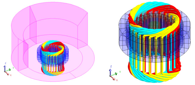
Computation domain of the 3D electromagnetic field.
The electric circuit in Fig. 5 associated with the field model of the motor contains the three phases of the stator windings, three voltage sources and eight identical elementary coils.
The step by step in time domain analysis of the motor operation considers the value of the time step 2 ms, from 0.00 s to 2.00 s, for LF applications and the time step 0.05 ms, from 0.00 s to 0.20 s, for the HF applications. These values ensure a good accuracy in the numerical evaluation of the low frequency (LF) harmonics, in the range [1 … 50] Hz, with step 1 Hz, and of the high frequency (HF) harmonics, in the range [75 … 2500] Hz, with the step 25 Hz.
The loaded motor operation with the imposed speed value 2880 rpm was considered, except in the last section of the paper, where the synchronous speed for the no-load motor operation is set to 3000 rpm.
The resistivity of rotor squirrel-cage material is 0.048e-6 Ωm. The broken bar (BB) fault is modelled by a value 107 times higher of the correspondent bar resistivity.
Current density in the rotor squirrel cage
The maps of the current density in the rotor squirrel cage for the healthy motor state (HE), Fig. 2, reflects the two poles spatial structure of the electromagnetic field.
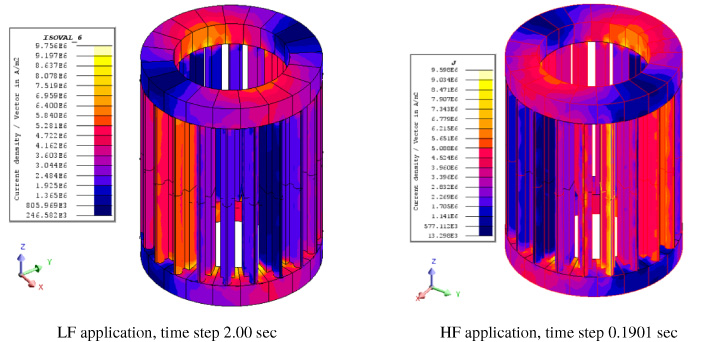
Maps of the current density in the healthy rotor squirrel cage.
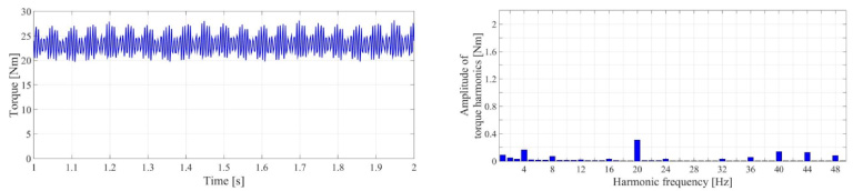
Time variation and LF harmonics of the motor torque, (HE) state of motor operation.
The time variation of the motor torque and the spectrum of this torque harmonics in the LF application in the healthy motor are presented in Fig. 3. The amplitude of the most important harmonic, of 20 Hz, Table 1, represents only 1.09 % from the mean value 23.39 Nm of the motor torque. The amplitude of the most important HF harmonic, of 850 Hz, Fig. 4 and Table 2 is much higher.
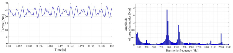
Time variation and HF harmonics of the motor torque, (HE) motor. Mean value = 23.12 Nm.
Amplitudes of motor torque LF harmonics in decreasing order
Amplitudes of motor torque HF harmonics in decreasing order
The most important LF harmonic of the rotor unbalanced force, with the mean value 10.34 Nm, Table 3, has the frequency 4 Hz, which is the double of the rotor currents frequency. The most important HF harmonic has the frequency 1150 Hz, Table 4.
Amplitudes of the LF rotor force harmonics in decreasing order
Amplitudes of the LF rotor force harmonics in decreasing order
Amplitudes of HF rotor force harmonics in decreasing order
The non-negligible values of the rotor force in the healthy state are the result of the slotting of stator and rotor cores. Due to the different number of stator and rotor slots, there is not a perfect symmetry of the two poles of the magnetic field in the motor air-gap.
Motor torque
The first elementary coil in yellow, Fig. 5, of the phase U of the motor is short-circuited through the resistor Rshc that connects the input and output terminals. The value considered for the Rshc resistance corresponds to an “acceptable” fault, for which the currents in the short-circuited coil and in all other coils of the motor are not over the rated value.
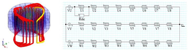
Coils of the phase U, the elementary short-circuited coil in yellow and the associated circuit.
The time variation of the motor torque in the LF application in the presence of the short-circuit (SHC) and the mean value 23.37 Nm are not sensible different from the correspondent (HE) result.
The HF results related the motor torque time variation and harmonics, Fig. 6 and Table 5. The most important HF harmonic, of 850 Hz, has the amplitude much higher than those identified in the LF application.
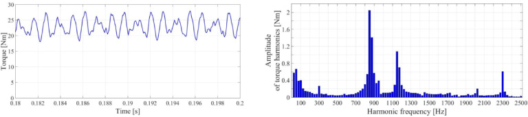
Time variation and HF harmonics of the rotor torque for (SHC) faulty state. Mean value = 23.06 Nm.
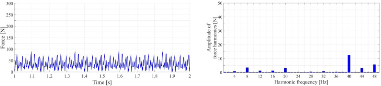
Time variation and LF harmonics of the rotor force for (SHC) faulty state.
Amplitudes of rotor torque HF harmonics in decreasing order, (SHC) fault
The time variation of the rotor unbalanced force in the LF application, with the mean value 35.22 N on the half of the rotor, Fig. 7, reflects the important influence of the (SHC) fault. The LF harmonic with the most important amplitude, 12.5 N, Table 6, has the frequency 40 Hz. The HF application offers a similar mean value of the rotor force, 35.20 N, Fig. 8. The most important HF harmonics, Table 7, with the frequencies 200 Hz and 950 Hz, represent 38.1% and 36.6% from the mean value.
Amplitudes of rotor force LF harmonics in decreasing order, (SHC) fault
Amplitudes of rotor force LF harmonics in decreasing order, (SHC) fault
Amplitudes of rotor force HF harmonics in decreasing order, (SHC) fault
Current density in the rotor squirrel cage
The volumes associated with the broken bar (BB) fault are identified through the yellow lines in Fig. 9. The two poles spatial configuration of the current density that characterizes the healthy motor, Fig. 2, disappears. The maximum of the current density in the (BB) fault case, which is 11.18 A/mm2, increases in comparison with the value 9.756 A/mm2 in the healthy motor case.
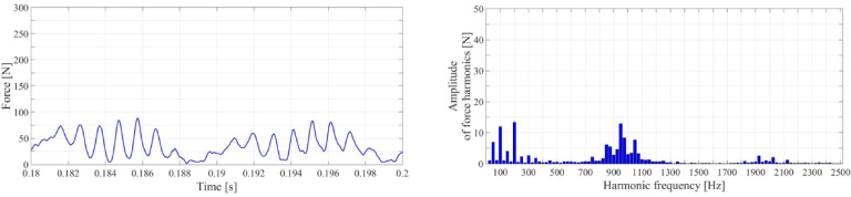
Time variation and HF harmonics of the rotor force for (SHC) faulty state. Mean value = 35.20 Nm.
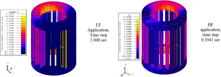
Maps of the current density in the rotor squirrel cage, (BB) fault.
The time variation of the rotor torque in the LF application, (BB) fault, Fig. 10, is very different from the (HE) and (SHC) results. The most important LF harmonic, Table 8, has the frequency 4 Hz. The amplitude of this harmonic is 9.15% from the mean value 15.63 Nm. Similar results shown in Fig. 11 and Table 9 are obtained in the HF application.

Time variation and LF harmonics of the motor torque for the (BB) faulty state.
Amplitudes of the motor torque LF harmonics in decreasing order, (BB) fault
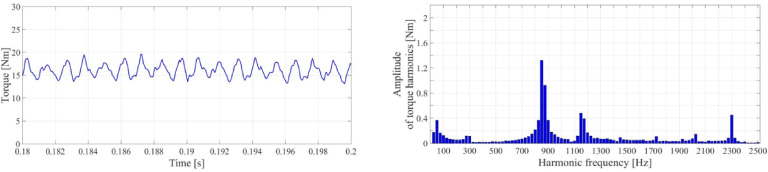
Time variation and HF harmonics of the motor torque for (BB) state. Mean value = 16.07 Nm.
Amplitudes of the motor torque HF harmonics in decreasing order, (BB) fault
The rotor force in the LF application, Fig. 12, with the mean value 181.03 N on the half of the rotor, reflects the very important influence of the (BB) fault. The LF harmonic of this force, with the most important amplitude, 48.2 N, Table 10, has the frequency 4 Hz. The HF application offers a similar value of the mean value of the rotor force, 191.8 N. The most important HF harmonic for the (BB) fault, Table 11, has the frequency 300 Hz.

Time variation and LF harmonics of the rotor force for the (BB) faulty state.
Amplitudes of rotor force LF harmonics in decreasing order, (BB) fault
Amplitudes of the rotor force HF harmonics in decreasing order, (BB) fault
Motor torque
The static eccentricity (ECC) fault is characterized by a non-uniform air gap, which values varies from a minimum and a maximum of 0.4 and 0.6 mm respectively, compared to 0.5 mm in the healthy motor.
The motor torque in the LF application is characterized by the mean value 23.31 Nm. The most important LF harmonic has the frequency 20 Hz and small amplitude, only 1.37% from the mean value. In the HF application, Fig. 13 and Table 12, the mean value of the motor torque is 22.49 Nm. The most important harmonic, with the frequency 850 Hz, has reduced but non negligible amplitude.

Time variation and harmonics of the rotor torque for the (ECC) faulty state.
Amplitudes of torque harmonics in decreasing order, (ECC) fault
The mean values of the rotor force are important, in the LF application 99.52 N and in the HF application 94.24 N, Fig. 14. The most important harmonics, with the frequency 40 Hz and 1050 Hz respectively, have the amplitudes 8.78% and 26.1% respectively from the correspondent mean values.

Time variation and HF harmonics of the rotor force, (ECC) fault.
Considering the HF applications, the results in Tables 13 and 14 offer the possibility to compare the influences of the three faults (SHC), (BB) and (ECC) on the rotor torque and on the rotor unbalanced force for loaded and for no-load motor operation. Thus, the influence of the (SHC) fault on the rotor unbalanced force is practically none affected by the motor operation load. The influence of the (BB) fault on the rotor force is very dependent on the motor load. In case of the (ECC) fault, the rotor unbalanced force decreases when the motor load decreases, but the decrease is not as important as in the case of the (BB) fault.
Motor torque and rotor unbalanced force, LOAD, mean values
Motor torque and rotor unbalanced force, LOAD, mean values
Motor torque and rotor unbalanced force, NO-LOAD, mean values
Taking as reference the healthy state, only the broken bar fault has a consistent influence on the mean value of the motor torque when the imposed speed motion model for loaded motor operation is considered. Related to the rotor unbalanced force, the important influences are in decreased order the broken bar fault, the rotor eccentricity fault and the stator short-circuit fault.
There are in all three faulty cases specific harmonics in the time variation of the motor torque and rotor force, with more or less important amplitudes in comparison with the mean values and compared with the amplitudes in the case of healthy motor.
The results in this paper are valid for the motor defined in introduction. The extrapolation of some of these to other induction motors must be done with precautions.
The investigation methodology based on finite element analysis in time domain, which offers a deeper understanding of electromagnetic phenomena, represents the future in the electrical machines research.