



Abstract
The authors have been studying the magnetic harmonic gear with the stackable structure. In this paper, we propose a new magnetic harmonic gear which has the stackable structure. This new magnetic gear is expected that a torque characteristics are improved. The maximum transmission torque is calculated by simulation. The torque characteristics of a proposed magnetic gear are compared with that of the past magnetic gear. As the result, the maximum transmission torque of a proposed type is improved approximately 5.96 times and the torque density is improved about 3.82 times.
Introduction
The magnetic harmonic gears are studied because they have the high torque density and the large transmission torque. Atallah et al. [1] proposed a harmonic magnetic gear. Many research [2–4] treated to improve the properties or to extend the applications with almost same structure. Ando et al. [5] studied the magnetic harmonic gear which has the stackable structure. In [5], ring shape magnets and iron plates are stacked alternately. In this report, such a magnetic gear is called Model A. And we propose a new structure of a magnetic harmonic gear here. It has the stackable structure, too. The new structure is called Model B. In this paper, we calculate the maximum transmission torque by simulation and compare the torque between both models. We verify that Model B is more excellent at the maximum transmission torque and the torque density than Model A.
Proposal of the new magnetic gear
The magnetic harmonic gear is structured of three coaxial rotors, which are called as an outer, an inner and a center. Its structure is the surface permanent magnetic gear. The outer and the inner have magnets. It is well known that the center rotor metamorphoses flux of inner magnets modulated harmonic magnetic flux.
As shown in [5], Fig. 1(a) shows a structure of inner in Model A. The outer has the same structure. The inner and the outer are structured of ring shape magnets, iron plates and segment magnets. In this magnetic gear, the inner is a high speed rotor and an input, the center is a low speed rotor and an output, and the outer is a stator. The segment magnets are pasted in the iron plates. Ring shape magnets are magnetized by the axial direction and the same pole is opposed. The segment magnets are magnetized by radial direction. The center is made of the plastic and laminated iron plates to avoid the eddy current.

The structure of inner of model A (Past) and Model B (New Proposal).
Figure 1(b) shows the structure of the inner in Model B which is newly proposed in this paper. The relation of an input and an output is same as Model A. Model B has two kind of layers. They use two types of segment type magnets in the magnetization direction. One is that the magnetic flux goes in the axial direction and we call it ‘Layer 1’. Another one is that the magnets are magnetized in the radial direction and we call it ‘Layer 2’. In both layers, adjacent magnets are magnetized in opposite directions. The Layer 1 and 2 are alternately stacked. When the layers are stacked, they form a Halbach array centered on Layer 2 (Fig. 2). The structure of outer is same as the inner. The center is same as Model A. Figure 3 shows an assembly of Model B. Tables 1 and 2 shows the dimensions of the past and a new proposed magnetic gear to be compared.

Staking of Model B.

Assembling Model B.
Dimensions of the magnetic gear (model A)
Dimensions of the magnetic gear (model B)
We consider the difference in the maximum transmission torque and the torque density between Model A and Model B by the 3D finite element analysis. The torque density is evaluated by dividing the maximum transmission torque by the volume of magnets.
The following model is used in simulation. In Model A, the inner and the outer are stacked 5 iron plates and segment magnets parts and 4 ring magnets. The thickness of segment magnets, iron plates and ring magnets are 3 mm and 4 mm respectively. The center rotor has 16 pole pieces in a circle and 5 rows in the axial direction. The thickness of the pole pieces is 4 mm. In Model B, the inner and the outer are stacked 4 Layer’s 1 and 5 Layer’s 2. The thickness of Layer 1 and Layer 2 are 4 mm and 3 mm respectively. The center is same as Model A. Figure 4 shows the photo of the center inner with 8 layers.
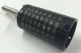
Photo of center rotor.
In calcutation of the maximum transmission, the outer and the center are steady, and the inner is turned at 10 rpm. The maximum transmission torque which takes the center defines the maximum transmission torque of the magnetic gear.
Table 3 shows the result of the simulation. In Model B, the maximum transmission torque is about 2.5 (1.83/0.73) times larger, and the torque density is about 2.2 times larger than Model A. Thus, the structure of Model B is effective for improvement of the maximum transmitted torque and the torque density.
We consider the reason why the maximum transmitted torque and the torque density have increased in Model B from the point of the magnetic flux density of the magnet surface. The magnetic flux density of the surface of the inner and the outer calculated for one turn is considered. As shown in Fig. 5 the magnetic flux density is calculated at 0.1 mm from the magnet surface of the inner rotor and the outer, and 15.5 mm from the end face. The position with 15.5 mm is corresponding to the center rotor in the axial direction of the magnetic gear.
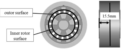
The place where magnetic flux density caluculated (surface, one turn).
The result of simulation and comparison
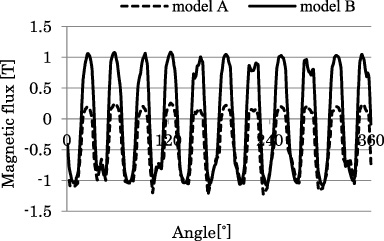
The magnetic flux density of both types is compared. Figures 6 and 7 show the magnetic flux density of the inner rotor and the outer. In Model A, the magnetic flux density is small at the segment type magnets part. In Model B, since all in the rotor circle are magnets, the change in polarity is uniform. So, Model B is twice larger at the amplitude magnitude of the magnetic flux density than Model A. Since the change in polarity is large, the maximum transmission torque of Model B become large.

Magnetic flux of inner rotor.
Magnetic flux of outer.
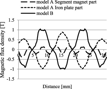
Next, we calculate the magnetic flux density of the surface of the inner rotor and the outer for axial direction. Figure 8 shows the point where the magnetic flux density is calculated. It is positioned at 0.1 mm distance from the magnet surface of the inner rotor and the outer. Model A has parts of the iron plate and the magnet, the magnetic flux densities are calculated at two places in the inner rotor and the outer respectively.

The place where magnetic flux density caluculated (surface, axial direction).
Figures 9 and 10 show the results. Where the magnetic flux goes in the radial direction, there are five places of 0 to 3 mm, 7 to 10 mm, 14 to 17 mm, 21 to 24 mm, and 28 to 31 mm. It is common to Figs 9 and 10, the magnetic flux of the iron plate part of Model A is sharp, but that of Model B has flat parts. It is considered that the width of the part where the magnetic flux couples is the cause of the difference between Model A and Model B.
Magnetic flux of inner.
In this simulation, an outer diameter and an inner diameter of the segment magnet for Model B are same as those of Model A. Therefore, the dimensions of the axially magnetized and radially magnetized magnets of Model B need to be considered.
Layer 1
In this section, we consider the axial thickness of Layer 1. The maximum transmission torque and torque density were calculated under the following conditions. The thickness of Layer 1 sets every 1 mm from 1 mm to 6 mm. The size of the magnet of radial direction and the thickness of Layer 2 is as shown in the Table 4.

Magnetic flux of outer.
Condition of thickness of Layer 1
Table 5 shows the result of the maximum transmission torque and torque density. When the thickness is 6 mm, the maximum transmission torque is 2.42 Nm. When the thickness is 5 mm, torque density is 5.62 × 10⁴ Nm/m3. Comparing this result with Model A, the maximum transmitted torque is about 3.32 times larger, and the magnet use efficiency is about 2.50 times larger.
Result for thickness of Layer 1
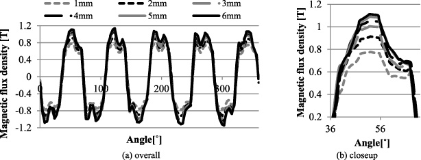
The magnetic flux density of the surface of the inner rotor is calculated for one turn same as in the Section 3. Figure 11 shows the result of the magnetic flux density of the inner rotor. It can be seen that the value of the magnetic flux density also increases as the magnet becomes thicker. Since the torque density is the maximum when the thickness is 5 mm, there is the optimum thickness for Layer 1.
The result of consideration 2.
In this section, we consider the thickness of Layer 2. The maximum transmission torque and torque density were calculated as in Section 4. The thickness of Layer 2 sets every 1 mm from 1 mm to 6 mm. The size of the magnet of radial direction and the thickness of Layer 1 are shown in Table 6.
Condition of thickness of Layer 2
Condition of thickness of Layer 2
Table 7 shows the result of the maximum transmission torque and torque density. When the thickness is 6 mm, the maximum transmission torque is 4.36 Nm, the torque density is 8.57 × 10⁴ Nm/m3. Comparing this result with Model A, the maximum transmission torque is about 5.96 times larger, and torque density is about 3.82 times larger.
Result for thickness of Layer 2
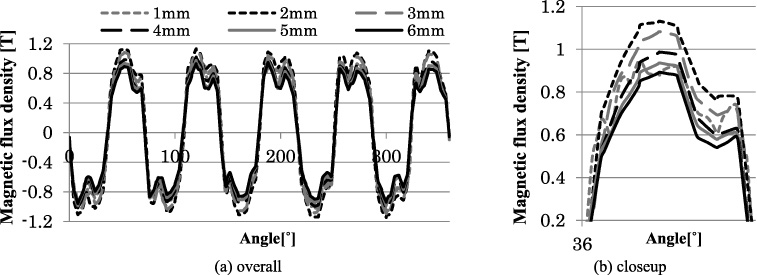
We calculate the magnetic flux density of the surface of the inner along the circle. Figure 12 shows the magnetic flux density of the inner rotor. The magnetic flux density is the maximum when the thickness is 2 mm. But the maximum transmission torque is the maximum when the thickness is 6 mm. For the maximum transmission torque, elements other than the magnitude of the magnetic flux density are conceivable.
The result of consideration 3 (one turn).
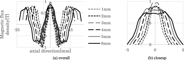
We calculate the magnetic flux density of the surface of the inner rotor for axial direction. Figure 13 shows the result of magnetic flux density of the inner rotor for axial direction. When the thickness is 6 mm, the amplitude of the magnetic flux density becomes largest in the axial direction. So, the thickness in the radial direction is more important than the magnitude of the magnetic flux density for the maximum transmission torque and torque density.
The result of consideration 3 (axial direction).
In this paper, the new structure of the magnetic harmonic gear with stackable structure is proposed. The effect of the new structure to improve the maximum transmitted torque and torque density is discussed. The torque density can be improved compared with the previous structure by the structure to make it all circumference Halbach array. From the results, Layer 2 (the radially magnetized magnet) should be designed to be thicker in the axial direction than Layer 1 (the axially magnetized magnet). The optimum rate of thickness should be considered in future.
Footnotes
Acknowledgements
A part of this research is supported by JSPS KAKENHI Grant Number 15K05930.