
Abstract
The acceleration performance of the pellet injection system by using the high-temperature superconducting (HTS) linear acceleration (SLA) to fuel the nuclear fusion reactor has been investigated numerically. To this end, the equivalent circuit model has been developed for analyzing the shielding current density in the HTS film. By using the model, the pellet injection system has been simulated. The results of the computations show that the acceleration performance depends on the parameter of the accelerating coil and the propulsion HTS film. Consequently, the pellet can be accelerated to about 2 km/s with the acceleration of 2 s. This acceleration speed of the SLA is about 1.7 times as great as that of the conventional pellet injection system.
Introduction
As is well known, a nuclear fusion can provide the long-term supply of energy, and the energy can be generated from a deuterium and a tritium used for the fuel of the nuclear fusion. The nuclear energy can be obtained from a small amount of the fuel, and it is quite clean. Therefore, it is expected that the nuclear fusion becomes a future energy source.
In the National Institute for Fusion Science (NIFS), a pneumatic pellet injection system is used on fueling to the nuclear fusion. This system injects some pellets made of frozen hydrogen gas into a plasma of a fusion reactor at the velocity of 1.2 km/s. For a tokamak-type fusion reactor, the pellets can be achieved into the plasma core by using the above-mentioned system. However, for the Large Helical Device (LHD)-type helical fusion reactor, the pellets melt at the edge of a plasma, and they do not reach the plasma core. Therefore, it is difficult to control a fuel with decreasing the fuel efficiency of the fusion reactor. This reason that the velocity of the injection is insufficient. According to the neutral gas shielding model [1,2], the pellet injection at a speed of 5–10 km/s is required to supply fuel to the plasma in the LHD-type helical fusion reactor.
In order to inject the pellets into the plasma core in a helical fusion reactor, Yanagi et al. recently propose a novel pellet injection system by using a Superconducting Linear Acceleration (SLA). In this system, a pellet container made of the HTS film can be electromagnetically accelerated such as a linear motor car. To this end, they adopt two types of the film for the propulsion and the levitation. If they use this system, they evaluate 5–10 km/s as the velocity of the pellet injection [3].
The purpose of the present study is to develop a numerical code for analyzing the time evolution of the shielding current density by means of an equivalent circuit model. By using the code, we investigate the acceleration performance of the pellet injection system by using the SLA.

A schematic views of (a) a Superconducting Linear Acceleration (SLA) for a propelling HTS and (b) an HTS current loop.
A schematic view of a pellet injection system used in the SLA is shown in Fig. 1(a). In the system, a pellet in a container is accelerated on the electromagnetic rails in the vacuum tube by using an HTS thin film. Here, the HTS film is for levitation and for propulsion. The pellet levitates by an electromagnetic force generated from the electromagnetic rails, and subsequently, it can be moved by the repulsive force acting between the coil and the propulsion film. In the present study, we simulate the pellet injection system by using equivalent circuit model. Note that we only consider the propulsion film to investigate the acceleration performance. Furthermore, it is found that a shielding current in the HTS film concentrates near the film edge due to the superconducting characteristics. Therefore, we can simulate the SLA by using the axisymmetric model of the equivalent circuit model.
In Fig. 1(b), we show a schematic view of an equivalent circuit model for a propelling HTS. By determining the symmetry axis as z-axis and choosing the centroid of an HTS film and a coil, let us use the cylindrical coordinate (r, θ, z). z 0 denotes the initial position of the HTS current loop and takes the centroid of the HTS. Also, v 0 is an initial velocity.
As mentioned above, since a shielding current I is localized near an HTS edge, a spatial distribution of I can be assumed by using an HTS current loop. The flow of I is given by width W, height b and radius R.
Under the assumption, Faraday’s law is equivalent to the following circuit equation:
A J–E constitutive equation of the equivalent circuit model is expressed as e = e
C(|I|∕I
C)
N
sgn(I). Here, e
C and I
C are the critical voltage and the critical current, and these can be defined by e
C ≡ 2πRE
C and I
C ≡ j
C
bW. Also, N is a positive constant. Incidentally, J–E constitutive equation is obtained from E
θ = E
C(|j
θ|∕j
C)
N
sgn(j
θ) [5], where E
θ is the θ-component of the electric field
A dynamic motion of an HTS current loop is governed by Newton’s laws of motion:
By combining (1) with (2), we obtain the following ordinary differential equations (ODEs)
On the basis of the method described in Section 2, we developed a numerical code for the equivalent circuit model. By using the code, we investigate the acceleration performance of the pellet injection system by using the SLA for the case with single coil and multiple coils. Throughout the present study, the geometrical and physical parameters are fixed as follows: R c = 5 cm, H c = 10 cm, 𝛼 = 20 kA/ms, m = 10 g, v 0 = 0 m/s, E C = 1 mV/m, b = 1 mm, and W = 5 mm.
Single coil
In this subsection, we investigate an acceleration performance of the pellet injection system for the single coil. It is important that a coil current I c is temporarily given by I c(t, z) = 𝛼t (z ≥ 0), where 𝛼 is an increasing ratio of an electric current. Firstly, the dependence of the mutual inductance M(z) on the position z is shown in Fig. 2. We see from this figure that the mutual inductance M monotonously decreases with the position z, and the value of M almost vanishes for z ≳ 20 cm.
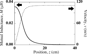
Dependences of the mutual inductance M and the velocity v on the position z for the case with z 0 = 1 mm,z p∕z limit = 5, R = 3.5 mm, N = 20, and j C = 1 MA∕cm2.
We also show the dependence of the velocity v on the position z in the Fig. 2. This figure shows that although the HTS can be accelerated by the single coil, the velocity v becomes almost constant for z ≳ 20 cm. This result means that there exists an acceleration region for 0 ≤ z ≤ z
limit. For this reason, we adopt the following coil current I
c in the present study.
Let us investigate an acceleration performance of the pellet injection system for the multiple coils. In Fig. 3, we show a schematic view of the multiple coils. In the present study, the number M of the coils is placed on z-axis at regular intervals so that interval becomes z
p. Moreover, determining the z-coordinate as an HTS position, we can expand the single coil model in Section 3.1 to the multiple coils one by using the following modulo operator: z
mod = mod(z + z
p∕2, z
p) − z
p∕2. As a result, the dynamic motion of the HTS film can be looped to produce a continuous in the region − z
p∕2 ≤ z
mod ≤ z
p∕2. Also, the coil current is written as follows:
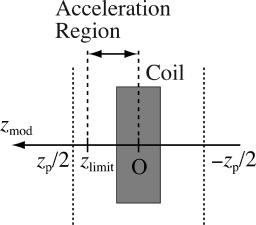
A schematic view of the multiple coils.
Let us investigate how the acceleration performance of the pellet injection system depends on the initial position z 0 of the HTS film, the increasing ratio 𝛼 of the coil current, the coil interval z p, and the radius R of an HTS current loop.
First of all, we simulate the pellet injection system by changing the initial position z 0. In Fig. 4, we show the time dependence of the velocity v for two cases of the initial position z 0. We see from this figure that the velocity v drastically increases by the 1st coil, and subsequently HTS is accelerated monotonously. In addition, the value of v for z 0 = 1 μm is larger than v for z 0 = 1 mm.
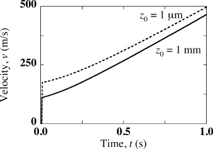
Time dependence of the velocity v for the case with z 0 = 1 mm, z p∕z limit = 5, R = 3.5 mm, N = 20, and j C = 1 MA∕cm2.
In order to compare the velocity v for the same number of coils, we define a final velocity v f at which the film passes through the 20th acceleration region. The final velocity v f is calculated as a function the initial position z 0 and is depicted in the Fig. 5. From this figure, v f monotonously decreases with z 0 for 1 μm ≤ z 0 ≲ 5 cm, whereas its value increases with z 0 for z 0 ≳ 5 cm. We found that when the initial position z 0 approaches the origin O, the acceleration performance improves. In practice, however, it is difficult to control the initial position on such a micro-scale. For this reason, the value of the initial position z 0 is fixed by z 0 = 1 mm.
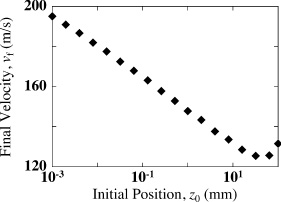
Dependence of the final velocity v f on the position z 0 for the case with z p∕z limit = 5, R = 3.5 mm, N = 20, and j C = 1 MA∕cm2.

Time dependence of the velocity v for the case with z p∕z limit = 2, R = 3.5 mm, N = 20, and j C = 1 MA∕cm2.
Next, we investigate how the acceleration performance of the SLA is influenced by an HTS current loop of radius R, and we calculate the velocity v for 0s ≤ t ≤ 2 s for the case with z p∕z limit = 2. It is found that the values of the velocity at t = 2 s are about v = 1.1 km/s and about v = 2 km/s for R = 2.5 cm and R = 4.5, respectively. Consequently, the pellet can be accelerated to about 2 km/s with the acceleration of 2 s. This acceleration speed of the SLA is about 1.7 times as great as that of the conventional pellet injection system. Incidentally, the number M of coils requires about 5.93 ×10³, and the distance of the electromagnetic rails becomes about 2.4 km. For this reason, it may be necessary to make the shape of the rail not straight but circular.
We next consider how the parameters, j C and N of the J–E constitutive equation affects on the acceleration performance. In the inset of Fig. 7, we firstly show two t–v lines for j C = 0. 3 MA∕cm2 and j C = 1 MA∕cm2. It is found that the velocity for j C = 1 MA∕cm2 is larger than that for j C = 0. 3 MA∕cm2. In Fig. 7, we also indicate the dependence of the final velocity v f on the critical current density j C. We see from this figure that the final velocity v f greatly increases with j C for j C ≲ 0. 4 MA∕cm2. On the other hand, the value of v f becomes constant for j C ≳ 0. 4 MA∕cm2. Although the acceleration performance increases with the critical current density, the velocity becomes constant for a high critical current density. This is because the amount of shielding current I is determined from j C b, and the shielding current I hardly change for j C ≳ 0. 4 MA∕cm2.
Secondly, the time dependence of velocity v in various values N = 10, 20, and 30 in Fig. 8. From this result, v hardly change for t ≲ 1.5 s whereas v becomes slow with increasing N for t ≳ 1.5 s. Consequently, the velocity v does not depend on the value of N with the acceleration of about 1 s.
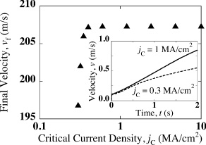
Dependence of the final velocity v f on the critical current density j C for the case with z p∕z limit = 5, R = 3.5 mm, and N = 20. The inset shows the time dependence of the velocity v for the case with z p∕z limit = 5, R = 3.5 mm, and N = 20.

Time dependence of the velocity v for the case with z p∕z limit = 5, R = 3.5 mm, and j C = 1 MA∕cm2.
The pellet can be accelerated to about 2 km/s with the acceleration of 2 s. This acceleration speed of the SLA is about 1.7 times as great as that of the conventional pellet injection system. Although the acceleration performance increases with the critical current density, the velocity becomes constantly for a high critical current density. This is mainly because the shielding current in an HTS film hardly changes. In addition, the velocity does not depend on the value of N with the acceleration of about 1 s.
Footnotes
Acknowledgements
This work was supported in part by Japan Society for the Promotion of Science under a Grant-in-Aid for Scientific Research (C) (No. 15K05926 and No. 17K06999). A part of this work was also carried out with the support and under the auspices of the National Institute for Fusion Science (NIFS) Collaboration Research Program. Moreover, the numerical computations were carried out on Fujitsu PRIMEHPC FX100 of the LHD Numerical Analysis Server in NIFS.