
Abstract
Considering the structure of modular multilevel converter (MMC-HVDC) valve, the coupling path of electromagnetic interference is analyzed. In order to accurately predict the radio frequency interference (RFI) produced by MMC-HVDC converter, the 3D model of sub-module is established which is the basic unit of converters, and the RFI caused by sub-module is simulated. Furthermore, the electric fields in the valve hall are calculated by three models. Model I includes all components, such as shells, grading rings. Taking the influence of coupling path into account, two simplified models of MMC-HVDC converter RFI are proposed. Model II and model III are simplified which take less calculating time and computer memory. Comparing the calculation results of simplified models with that of detailed model, the error analysis of electric field has been carried out.
Introduction
MMC-HVDC can precisely and flexibly control active and reactive power independently with less of harmonics weakening filter equipment. Moreover, MMC-HVDC will not increase the system short capacity, and the polarity of DC voltage remains unchanged when the power flow turns over [1].
The structure of MMC-HVDC converter was first proposed by A. Lesnicar and R. Marquardt in 2002 [2]. With the continuous improvement of power system voltage, the converter adopts more and more sub-modules which are the basic units resulting in RFI. Besides, there are many interference sources and complicated transmission routes, therefore the electromagnetic environment of MMC-HVDC converter station is very complex [3–5]. Many MMC-HVDC converter stations have been established, and the radio frequency interference in converter hall and around the converter station has attracted increasing attention. There is also electromagnetic disturbance in the converter system itself. The electric interference may disturb the function of electronic devices in the valve hall, which may threat the safety and stability of the system. There are many studies on RFI in traditional HVDC converter station [6–8]. However, there is little research on the RFI of MMC-HVDC converter [9–12]. The electromagnetic compatibility of converter station is one of the key subjects in the design, construction and operation of MMC-HVDC [13]. Study on electromagnetic disturbance characteristics of MMC-HVDC converter station can help improve the relevant standards and promote the development of MMC-HVDC.
In this paper, firstly, the coupling path of transient voltage conducting in converters is analyzed. Moreover, adopting antenna theory, the radio interference model of the sub-module is proposed. The electric fields around the sub-module are calculated. Regarding the sub-module as the radiating unit, each operating sub-module contributes to the total RFI of MMC-HVDC converter. The detailed model of converter valve is put forward, which contains hundreds of sub-modules, but it takes long time to calculate the RFI inefficiently. Taking the influence of coupling path into account, two simplified models of MMC-HVDC converter are proposed. The electric field of a MMC-HVDC converter valve is calculated by the detailed model and the two simplified models. Comparing the calculation results of simplified models with that of detailed model, the error analysis of electric field has been carried out. Satisfying the requirement of precision, different models suit to calculate the electric field in different frequencies with less calculating time. The electric fields near the AC bus, DC bus, the up arm of phase A and low arm of phase C in converter hall are demonstrated. There are some circuits working in the voltages of 5 V or 15 V inside the sub-module, such as drive and control circuits which are easy to be disturbed. Besides, the sub-module should do some EMC test, such as Electrostatic discharge immunity test (IEC61000-4-2) [14], Radiated, radio-frequency, electromagnetic field immunity test (IEC61000-4-3) [15], Electrical fast transient/burst immunity test (IEC61000-4-4) [16] and so on. Effective shielding measures enable sub-modules to meet those standards, so it is necessary to design the shield of sub-modules. Besides, Electromagnetic disturbance will be produced during the operation of MMC-converters. There are some standards about the electric fields of substations, such as CISPR and CIGRE [17], so it is necessary to design the shield of valve hall. Furthermore, taking use of the RFI model of MMC-HVDC converter valve to predict the interference level, we can provide some suggestion on electromagnetic shielding of the converter station during designing the project. In this way, the electromagnetic environment meets standards, and the EMC ability of MMC-HVDC converter valve can be improved at the same time.
Electromagnetic radiation model of MMC-HVDC converter
Coupling path of electromagnetic interference
MMC-HVDC converter system comprises 6 half-bridges, and each bridge includes some converter towers, which consists of sub-modules, cooling systems, grading rings, metal fittings and insulate supporting pillars. The up-bridge and down-bridge make up a phase unit [18,19], as shown in Fig. 1. By controlling the sub-modules, the converter system can output the step voltage wave, which simulates the expected voltage wave [20], as shown in Fig. 2. Besides, Fig. 3 is the circuit diagram of sub-module which contains insulated gate bipolar transistor (IGBT), control circuit, diode and capacitor.
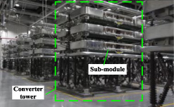
The transient voltage and current conduct through accessory devices, such as sub-module shell, grading ring, and this part of RFI has high frequency but small amplitude. Moreover, the large transient voltage and current conduct through the copper bar, and this main part of RFI has large amplitude. Figure 4 shows the MMC-HVDC converter containing hundreds of sub-modules, which makes it complex. The coupling path equivalent circuit diagram of series sub-modules is shown in Fig. 5. C1 represents the equivalent capacitor between sub-module shell and copper bar. C2 represents the equivalent capacitor between the sub-modules. C3 represents the equivalent capacitor between copper bar and ground. The actual MMC-HVDC converter system layout is shown in Fig. 6. Because the DC bus bars are 30 meters, and the DC bus bars are close and above to the valve towers, high frequency currents are easier to radiate through such long straight bus bars. Besides, the stray parameters of the valve tower have great influence on the electric field near the DC bus and the bridge arms. In the valve hall, the AC bus is connected to the copper bar by the aluminum stranded wire, and the main radiators on the AC side are copper bars and stranded wire.
The sub-module shell connects with the high voltage part, and there is small voltage difference between adjacent sub-modules, so the transient voltage and current value conducting through C2 is small. The main current conducts via copper bar, so the transient voltage and current conducting via C1 is larger. C1 and C3 are the main coupling paths of transient current propagation. Furthermore, the sub-modules are arranged side by side, therefore the RFI caused by middle sub-module may be reduced by the adjacent shell. The analysis of coupling path contributes to simplify model reasonably.
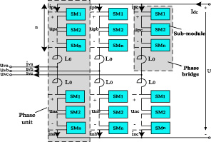
Topology of MMC-HVDC converter valve.
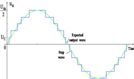
Output voltage.

Circuit of sub-module.
MMC-HVDC converter valve.
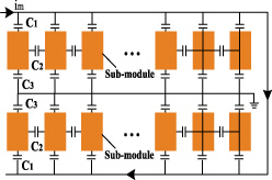
Coupling path diagram.
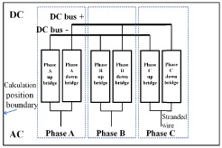
The MMC-HVDC converter layout.

Sub-module. (a) Inner structure, (b) Complete sub-module, (c) Mesh of sub-module.
Radio interference model of sub-module
Sub-module is the basic unit of converter valve. Its inner structure is shown in Fig.7(a), and the main devices are connected by copper bar. Based on the sub-modules used in practical engineering shown in Fig. 7(b), the electromagnetic field calculation model of sub-module is proposed. In order to save computation time and obtain accurate calculation results, the surface of the model is divided into triangles, and the coarse mesh of the shell is made, while the fine mesh of the copper bar is performed. The calculation area is on the side of IGBT in order to obtain the most serious RFI of sub-module, as shown in Fig.7(c).
Radio interference model of converter
As the converter valve tower is very complex, if the impacts of all components on the radio interference are considered, the amount of calculation will increase significantly. In order to reduce the cost of calculation, and ensure the reasonable accuracy at the same time, some simplifications are made to the model by neglecting the influence of spurious parameters on the electromagnetic disturbance.
Comparing the effects of spurious parameters on the calculation results of electromagnetic interference, the RFI calculation models of valve tower are established. The model I shown in Fig. 8(a) contains all parts of valve tower, such as sub-module shells and insulation supports. The model II and model III are shown in Fig. 8. The equivalent stray parameters of model II and model III are different from those of model I. Model III takes the stray parameter C3(III) into account, and C3(III) is the parameter between the copper bar and ground. Model II takes the stray parameters C1(II), C2(II), C3(II) and C4(II) into account, the C1(II) is the parameter between the shell and the copper bar, the C2(II) and C4(II) are the parameters between the sub-modules, and the C3(II) is the parameter between the copper bar and ground. The stray capacitor C2 between sub-modules is related to the area of the shell and the spacing of the sub-modules. In model I, C2 is the actual stray capacitor between sub-modules, and the stray capacitor of a group is six sub-modules’ C2 in series. In model II, the six sub-modules are equivalent to a whole part, and the stray capacitor C2(II) is larger than six C2 in series in model I.

RFI model of converter. (a) Model I, (b) Model II, (c) Model III.

Radiation noise sources. (a) Output voltage waveform of sub-module, (b) Spectrum of voltage.
The operation of sub-module is decided by IGBT turn-on and turn-off. When the IGBT operates, the transient voltage and current will be caused. The rated voltage of sub-module is used as the reference value. The waveform of sub-module voltage converted into per-unit value is shown in Fig. 9(a), and the spectrum is shown in Fig. 9(b). Besides, the spectrum value is used as the excitation source in calculation.
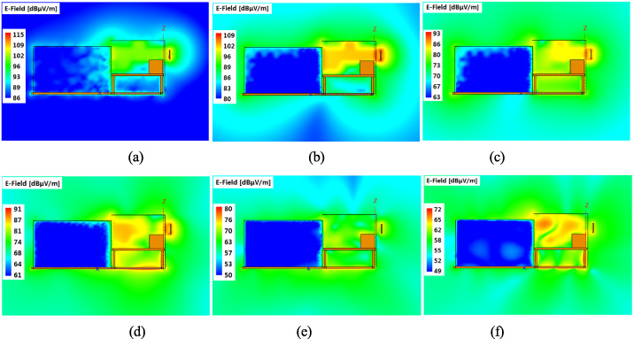
Electric field of sub-module. (a) 10 MHz, (b) 50 MHz, (c) 100 MHz, (d) 300 MHz, (e) 500 MHz, (f) 700 MHz.
When considering the large size and complicated structure of MMC-HVDC converters, the model of finite planar dipole array is proposed with a hybrid method containing RWG (Rao-Wilton_Glisson) function and an equivalent dipole moment model. In the dipole moment model, the surface current distribution of RWG edge element on each divided area can be generated by an infinitesimal dipole antenna, while the model has an equivalent dipole moment and power. In this way, the total radiated field could be calculated by the vector addition of all infinitesimal dipoles. This method improves the computation accuracy and enhances the efficiency. Dipole moment
Equation (2) and Eq. (3) are the precise equations in computing electromagnetic field. The MMC-HVDC converters electromagnetic field could be calculated by vector addition of all dipole antennas as shown:
The electric field of sub-module
The calculation area is around the sub-module, as shown in Fig. 7(C), and the electric fields are calculated in different frequencies. Copper is the main electromagnetic radiator, as shown in Fig. 10, and RFI mainly radiates from the copper out of the shell. The electric field is high at the driver circuit, because the circuit is near to IGBT. With the increase of frequency, the maximum of the electric field decreases, and the difference between external and internal electric field of sub-module is also reduced. High frequency electromagnetic field is easier to radiate via copper bar. The sub-module shell has a certain shielding effect against the radiation disturbance generated by other sub-modules, and the shell can restrain the radiation electromagnetic disturbance produced by the sub-module. Besides, the drive and the IGBT will be placed in the shielding box. This can not only reduce the effects of disturbance caused by the adjacent sub-modules on the drive circuits, but also reduce the effects of disturbance caused by IGBT on itself driving circuits in the sub-module. The shielding box and the sub-module shell can prevent the radiation electromagnetic disturbance, so the electric field emission will not generate problems in adjacent sub-modules. Besides, the immunity of sub-modules can meet the standards requirements of IEC immunity and radiation disturbance by taking such measures of shield.
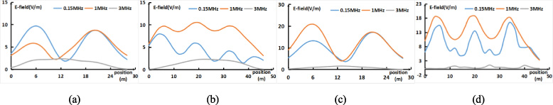
Simulation results curves of four domains. (a) near phase C, (b) near DC bus, (c) near phase A, (d) near AC bus.
The radio frequency interference were calculated in four areas which are located in a distance of typically 3 meters away from the tower and inside the valve halls. The electric fields near the AC bus, DC bus, the up arm of phase A and down arm of phase C in converter hall are demonstrated, and the calculated position of the electric field in this paper is the rectangular around the whole converter valve, as shown in Fig. 6. Because the bridge arms of phase B located between phase A and phase C cannot be reached by people, the electric fields near the bridge arms of phase B are not calculated in this paper. The diagrams shown in Fig. 11 represent the electric field versus distance in the range from 150 kHz to 3 MHz. There are three curves given in each figure, which reflect the field strength varying with frequencies in four domains.
The maximum value of 0.15 MHz electric field is about 17 V/m, which is near the DC bus bar, and the electric field around AC bus bar is greater than that around DC bus bar. The maximum value of 1 MHz electric field is about 20 V/m, which is near the AC bus bar, and the electric field around AC bus bar is greater than that around DC. Three peak values are near the 3 phase AC bus bars. The maximum value of 3 MHz electric field is about 2 V/m, and the electric field around DC bus bar is greater than that around AC. The maximum value of 15 MHz electric field is about 0.17 V/m, which is near the AC bus bar. The maximum value of 30 MHz electric field is about 0.07 V/m, which is near the AC bus bar, while there is a little difference between DC bus electric field and AC bus electric field.
Around DC bus and AC bus, 1 MHz electric fields are much higher than that of 0.15 MHz and 3 MHz, while 1 MHz electric fields and 0.15 MHz electric fields are equal at some positions near phase C and phase A. The maximum electric field near phase B appears on the DC bus side. As shown in Fig. 6, the spatial position of the DC positive and negative bus is asymmetric, and the negative bus near phase A is longer than the positive bus, and the positive bus near phase C is longer than the negative bus. The positive pole is as long as the negative bus near phase B, and the sum of their lengths is longer than that of the other two phases, so the DC bus near the B phase is more favorable for electromagnetic wave radiation. The electric fields near the DC bus of phase B are the largest.
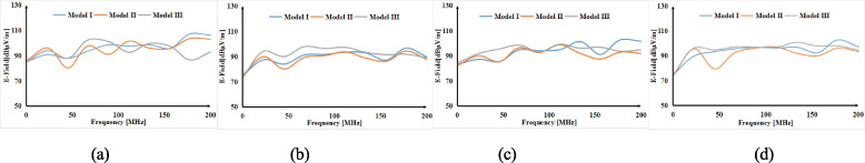
Electric fields of three models. (a) near phase C, (b) near DC bus, (c) near phase A, (d) near AC bus.
The three models aforementioned are used to calculate the electric field in four areas. The distance between the model and calculated position is 3 meters. The electric fields of three models are presented in Fig. 12. Regarding the model I results as the basic value, taking the electric field near the AC bus as example, the relative errors percentage between the other two models results and the results of model I are shown in Table 1.
Three models electric field calculated results
Three models electric field calculated results
Computing time and memory among three models
The stray parameters near DC bus of model II are approximately consistent to model I, so the results of model II near DC bus are extraordinarily close to model I. The electric fields near the bridge arm are greatly influenced by the stray parameters of the valve tower. Therefore, in the high frequency, the results near the phase A and the phase C bridge arms of model II are closer to the results of the model I.
The error of model II is smaller in the domain around DC bus, and the error of model III is smaller in the domain around AC bus. The C1 (II) and C3 (II) in model II make the error of the current on the AC copper bar get larger in high frequency, so the error of the electric fields near AC bus bar calculated by model II is large. Model II contains stray parameters C2 (II) and C4 (II), so model II is suitable for calculating the electric field near the valve tower and the DC bus. Besides, in the high frequency, model II has a high accuracy, but it also needs a lot of time and memory. Model II contains errors caused by the stray parameters C1 (II) and C3 (II), which make the calculation error of electric field near AC bus bar larger. Firstly, in both the low and high frequency, model III needs the least of computation time and memory. The electric fields of one tower are calculated by the three models in the frequency range of 50 MHz–200 MHz, and the time and memory for calculations are shown in Table 2. Therefore, if the accuracy is little difference, from the point of saving computing time and memory, model III is better. Secondly, when it comes to the electric field near the AC bus, the error between model III and model I is smaller in the frequency range of 50 MHz to 130 MHz. Finally, considering computing time, memory and error, model III is better when the electric field near AC bus is studied around 100 MHz.
To obtain the accurate results and save the calculating time, the model II is suitable to calculate the electric field around the DC bus, and the model III is suitable to calculate the electric field around the AC bus. However, when the frequency is near 100 MHz, the errors of model II and model III are both within the allowable range, and the computation time of model III is greatly reduced.
Using the method of moments, the electric field around a sub-module is calculated, and it is decreased with the increasing of frequency. The sub-module shell has a certain shielding effect against the radiation disturbance, and the immunity of sub-modules can meet the standards requirements of IEC immunity and radiation disturbance by taking such measures of shield. Besides, the copper is the main radiator, and the electric field near the copper bar is always the maximum. When it comes to the RFI in the converter hall, based on a MMC-HVDC converter, the models of converter valve are established. The electric field around the AC bus bar is greater than that around DC in the frequencies between 0.15 MHz and 1 MHz, and the maximum of electric field is shown near the bus. Electric field around DC bus bar is greater than that around AC in the frequencies between 3 MHz and 6 MHz, and the maximum value of electric field is shown near phase B bridge. The electric field of 15 MHz around the converter is similar with that of 30 MHz, both of which are much less. The electric field decreases with the increase of frequency except 1 MHz. Ignoring the spurious parameters between sub-modules. The errors of electric field calculated by the simplified models are allowable, and the computing time is reduced. Besides, model II is suitable to calculate the electric field around the DC bus, and model III is suitable to calculate the electric field around the AC bus. When the frequency is lower than 100 MHz, model II is a better choice. When the frequency is higher than 100 MHz, model III is a better choice.
Footnotes
Acknowledgements
This work is supported by the National Key Research and Development Program (Grant No. 2016YFB0900900).