
Abstract
In this research, we studied the rigidity of superconducting magnetic bearings (SMBs) due to the difference in superconductor arrangement. I The SMB with one large superconductor fabricated in a previous study and the SMB with two small superconductors arranged separately in this study were compared. The rigidity in the axial direction, radial direction, and pitching direction of each bearing were measured. However, since the total volume of the superconductor used for the two SMBs is different, the rigidity per unit volume was compared. The results confirmed that the rigidity per unit volume in all directions is larger when a plurality of small superconductors is used. In addition, this study verified the characteristics of each SMB by preparing a flywheel with two SMBs and rotating them.
Introduction
A magnetic levitation system with superconducting magnetic bearings (SMBs) is extremely useful because it can achieve stable floating with high rigidity without control [2–5]. For this reason, various studies on SMB are underway. However, studies on the rigidity of SMB owing to differences in superconductor (SC) arrangement methods are rarely conducted. In this research, we compared the rigidity of SMB using one large SC bulk we developed in the past and the rigidity of SMB separately arranged for the two SCs developed in this research. The differences in rigidity were investigated according to the SC arrangement method. When comparing the rigidity, since the bulk SC size and number are different in each SMB, it is impossible to simply compare the rigidity of both SMBs. Therefore, the total volume and total area of the bulk SC used for each SMB must be calculated. Using these results, the rigidity of SMB of both methods was compared by calculating the rigidity per unit volume and per unit area. In addition, we confirmed the influence of SMB configuration on whirling resonance and pitching resonance by incorporating a flywheel in the SMB and driving it.
Experimental equipment
Construction or structure of the SMB in the previous and present study
The SMB developed in the previous study is shown in Fig. 1 [1]. As can be seen from the figure, the single large cylindrical bulk SC at the center is the axis, and there are four permanent magnets and three magnetic flux converging parts in the levitating rotor. There is also a permanent magnet (PM) at the bottom that increases the levitation force by generating repulsive force.
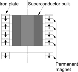
Construction of SMB in the past study.
The SMB developed in this study is shown in Fig. 2. The SMB has a configuration that allows the SCs to be arranged separately. The height from lower end of the PM to upper end of the SMB rotor in the previous study and the height from lower end of the rotor to the upper end of the SMB rotor in this study are almost same. The size of the SC in the SMB is shown in Table 1.
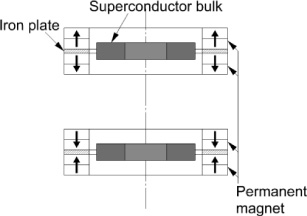
Construction of SMB in this study.
Size of SC
The flywheels developed in the previous and present study are shown in Fig. 3 and Fig. 4, respectively. The difference between the SMBs in the past and present study is the location of the flywheel. In the previous study, the flywheel was placed under the SMB; in the present study, the SCs are arranged separately, making it possible to place the flywheel between the separated SMBs. With this constitution, it is possible to levitate the flywheel with support at both ends, whereas in the past, the flywheel was levitated with cantilever support.
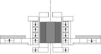
Construction of flywheel in the past study.
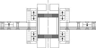
Construction of current flywheel in this study.
We measured the magnetic flux density (MFD) inside the SMB rotor and compared it with the results of static analysis by JMAG software. The measurement and analysis were conducted in an area 20 [mm]–26 [mm] from the axial center of the SMB as shown in Fig. 5.
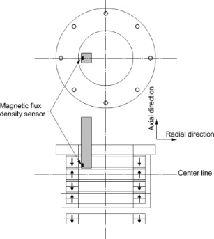
Measurement of magnetic flux density.
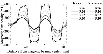
Comparisons of the MFD results in the radial direction in the previous and present study are shown in Fig. 6 and Fig. 7, respectively. The measurement and analysis results showed good agreement. The SMB in the previous study showed three magnetic flux converging parts while there are two magnetic flux converging parts in this study. The maximum value of magnetic flux density was approximately 850 [mT] and both showed good agreement. This convergent magnetic flux increased to about twice as much as the surface magnetic flux density of the PM alone.

Comparison of MFD in radial direction in the previous study.
Comparison of MFD in radial direction in this study.
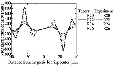
Comparisons of the MFD results in the axial direction in the previous and present study are shown in Fig. 8 and Fig. 9, respectively. The measurement and analysis results show good agreement. The maximum value of magnetic flux density was approximately 550 [mT], and both were about the same. Here, the location of the superconductor in the previous study ranged from −29 [mm] to 17 [mm]; in this study, the superconductor was located in two places: −28 [mm] to −20 [mm] and 20 [mm] to 28 [mm].
Comparison of MFD in axial direction in the previous study.
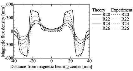
Comparison of MFD in axial direction in this study.
Radial restoring force of SMB in the previous and present study
The measurement results of the radial restoring force are shown in Fig. 10 and Fig. 11. Figure 10 shows the restoring force of approximately ±60 [N] with displacement of ±1.5 [mm] of the SMB in the previous study. Therefore, the radial rigidity is 41 [N/mm]. Figure 11 confirms the restoring force of approximately ±30 [N] with displacement of ±1.5 [mm] of the SMB in this study. Therefore, radial rigidity is 18 [N/mm].
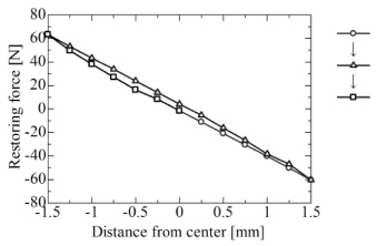
Horizontal restoring force of SMB in the previous.
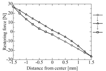
Horizontal restoring force of SMB in this study.
The measurement results of the axial restoring force are shown in Fig. 12 and Fig. 13. Figure 12 shows confirms the axial restoring force of 180 [N] at 2 [mm] in the upward direction and 200 [N] at 2 [mm] in the downward direction. Therefore, the axial rigidity is 96 [N/mm]. Figure 13 confirms the restoring force of approximately ±90 [N] at displacement of ±2 [mm] of the SMB in this study. Therefore, the axial rigidity is 46 [N/mm].
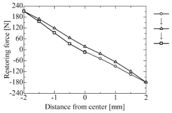
Axial restoring force of SMB in the previous study.

Axial restoring force of SMB in this study.
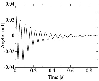
Pitching vibration was measured by giving free vibration in the SMB in the pitching direction. The results are shown in Fig. 14 and Fig. 15. Pitching rigidity was calculated from Fig. 14 and Fig. 15. The results confirm that the pitching rigidity of SMB in the previous and present study are 38.3 [N ⋅ m/rad] and 27.8 [N ⋅ m/rad], respectively.
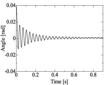
Time career reply of angle at SMB in the previous.
Time career reply of angle at the SMB in this study.
The total volume and surface area of the bulk SC in the SMB of the present study is approximately 35% and 71% of that used in the SMB of the previous study, respectively. For this reason, we compared the rigidity per unit volume and per unit surface area.
The volume and surface area of SC are listed in Table 2. The results are summarized in Table 3 and Table 4. The results show that the radial rigidity per unit surface area and axial rigidity per unit surface area of the SMB of this study is approximately 65% of that in the previous study. This corresponds to the fact that there were three magnetic flux converging parts in the SMB of the previous study, whereas there are two magnetic flux converging parts in the SMB of this study. However, the radial rigidity per unit volume of the bulk SC in the SMB of this study is approximately 126% of that in the SMB of the previous study. In addition, the axial rigidity per unit volume of the bulk SC bulk in the SMB of this study is approximately 138% of that in the SMB of the previous study.
Volume and surface area of SC
Volume and surface area of SC
Rigidity of SMB in the previous study
Rigidity of SMB in this study
From this, it was possible to maintain the rigidity while suppressing SC usage by arranging the SC separately.
In this study, the flywheel shown in Fig. 3 and Fig. 4 was driven. The frequency response is shown in Fig. 16 and Fig. 17.
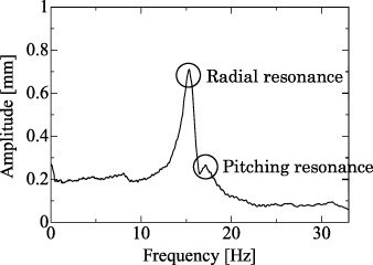
Frequency response of angle at SMB in the previous study.
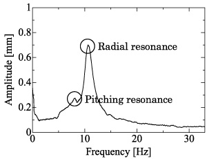
Frequency response of angle at SMB in this study.
From this result, the frequency of the whirling resonance of flywheel in the past and that of the flywheel in this study was approximately 15 [Hz] and 10 [Hz], and the maximum whirling amplitude was approximately 0.7 [mm] at both case. Also, the flywheel in the past, pitching resonance was confirmed at approximately 18 [Hz]. On the other hand, at the flywheel in this study, pitching resonance was confirmed at approximately 8 [Hz]. From these results, the flywheel in this study is considered to be a suitable system for high-speed driving because the whirling resonance and pitching resonance occur at low frequencies.
In this study, we developed an SMB supported at both ends. We improved the radial, axial, and pitching rigidity per unit volume of bulk SC by supporting both ends. Furthermore, the SMB of this study has two advantages because it is a levitating system with low radial rigidity and pitching rigidity.
The first advantage is that when the flywheel was driven, it was possible to generate radial resonance and pitching resonance at low frequencies.
The second is that the vibration amplitude of the flywheel at high frequencies is small.
Therefore, it was confirmed that this levitation system is suitable for high-speed driving.