
Abstract
This paper is intended to stimulate discussion of some effects of not properly accounting for material microstructure in some established methods of measurement and prediction of losses in electrical steel laminations. Aspects of methods which have been used for many years are briefly discussed and some constraints or pitfalls are raised which users should be aware of. The basic cause of losses is summarised in order to set the scene for discussion of the analysis of losses into classical eddy current, hysteresis and anomalous loss. The possible presence and consequences of transverse flux in grain-oriented (GO) steels is raised followed by an explanation of some effects of the strong anisotropy of GO steel on flux density, magnetic field and loss measurement in stacks and single strips of GO steel. The presentation concludes with some questions on how circular rotational magnetisation can be made and precautions needed when assessing the effect of flux harmonics on the losses.
Introduction
Many methods of magnetic measurement and analysis or prediction of the performance of electrical machine cores are directly or indirectly related to the texture and size of grains in the steels. Furthermore, the fundamental reorganisation of domains during magnetisation can also have a significant effect. These parameters are rarely included in material or core performance prediction models.
The effect of not accounting for these factors is not well quantified. It is always assumed that their effects are small and this is often the case. However when magnetised at high flux density or frequency or when flux harmonics are present, their influence might be greater than expected.
The purpose of this contribution is to show and explain why caution is necessary in this area particularly when dealing with grain-oriented (GO) steel. The influences of its large grains and strong magnetocrystalline anisotropy which strongly control its unique domain structure is described in the context of how it might affect the interpretation of some types of measurements or analysis. Obviously the fundamental principles of magnetism apply on a magnetic domain scale but there is no reason we can simply extrapolate what we believe happens at this level to practical measurements and analysis of material properties of engineering relevance.
Specific topics to be discussed include (a) the presence of a component of loss in GO steel due to transverse flux which is no detected in the Epstein frame measurement or when using the Single Sheet Tester (SST) (b) whether the instantaneous magnetisation can really be made to be perfectly constant in magnitude and rotate at constant velocity needed for rotational loss measurement (c) the influence of texture on the magnitude and direction of the localised flux density
Some of the above phenomena affect the accuracy of routine magnetic measurements and can contribute to the building factors of transformer cores. Others affect the way in which we understand and make use of magnetisation processes in magnetic measurements. The practical relevance and importance of most of these factors are probably generally low. However, this paper is intended to increase awareness that established methods of analyses are not always based on solid foundations and sometimes not fully relevant to today’s increasing demands for accurate magnetic characterisation over wide ranges of magnetisation conditions. Too often users of magnetic test systems are not aware of the limitations or assumptions which have to be made when interpreting their results. It is hope that some of the content of this paper will stimulate the consideration of more knowledge-based characterisation of GO steel, in particular, taking account of the influence of its unique microstructure.
Cause, analysis and prediction of losses
The fundamental, well established, relationships between components of surface magnetic field
Variation of hysteresis, classical eddy current and excess loss per cycle with frequency in a typical GO steel.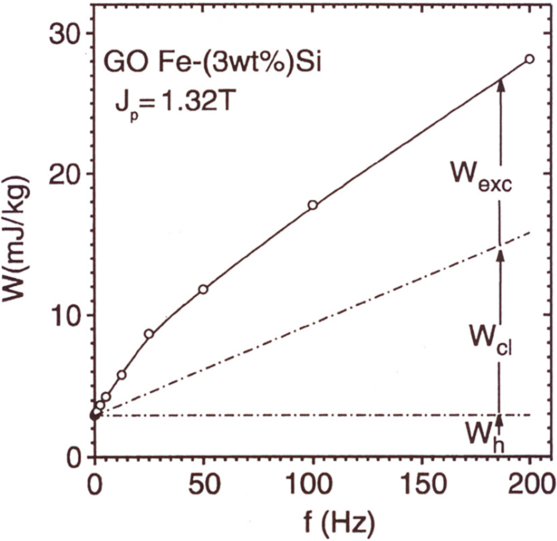
Figure 1 shows the traditional way of separating the loss per cycle of magnetisation in electrical steel into three components. The DC hysteresis loss per cycle is assumed constant. When added to the calculated classical loss per cycle, the sum is always less than the total measured value so a third component, initially called the anomalous loss but now more often called the excess loss, is added to account for this difference. It was assumed that this loss component is present due to domain walls movement at power frequencies through the material or to general reconfiguration of domain structures both causing additional eddy current and hysteresis losses. If the flux density varies sinusoidally with time, the total loss is often expressed in terms of the hysteresis, classical eddy current and excess components in forms such as
where
The approach is useful but there are pitfalls which users should be aware of. Firstly, it is well known that the number of domain walls in motion under dynamic magnetisation changes with
The second point to note in the use of the separation method is that the classical eddy current loss is derived and calculated based on assumptions which are gross approximations. It was found [3] that good agreement occurred provided relative permeability
There are many approaches to predicting B-H loop shapes and losses. These include well known Preisach, Jiles-Atherton, vector and dynamic hysteresis and statistical models. Most require DC characteristics, thickness, resistivity, plus at least one measured ac loss value in order to model B-H characteristics and hence losses. However they all ignore micro-magnetic behaviour which causes poor reliability especially for thin material or magnetisation extremes. In many methods, it is basically necessary to solve the following well known diffusion equation under dynamic conditions for unidirectional magnetisation.
where
(a) Typical field variation on the surface of a sheet of GO steel in a demagnetised state. (b) Magnetisation conditions in a single grain with magnetisation 
It is well known that the localised magnetic field on the surface of GO steel varies in magnitude and direction particularly from grain to grain such as shown in Fig. 2a [6]. It used to be thought that there might be direct correlation between the surface field variation and the orientation of individual grains but now it appears more likely that it depends also on the demagnetisation factors of individual grains as shown in Fig. 2b. From Eq. (1) the following commonly used expression can be obtained to calculate the total loss under two dimensional (2-D) magnetisation
where
Variation of the loss with flux density along the RD due to transverse components of flux density in a strip of commercial GO steel magnetised along its RD.
The effect of the transverse component is more apparent in a laboratory produced, very poorly oriented steel as shown in Fig. 4 [8]. When the overall flux density along the RD is 1.10 T, the longitudinal component shown in Fig. 4b varies between 0.60 T and 1.30 T and the transverse component shown in Fig. 4c lies within a range between 0.05 T and 0.30 T producing a significant component of loss.
Longitudinal and transverse flux density components in a laboratory produced strip of poorly oriented GO steel. (a) Grain and static domain structure. (b) Distribution of longitudinal flux density. (c) Transverse flux density.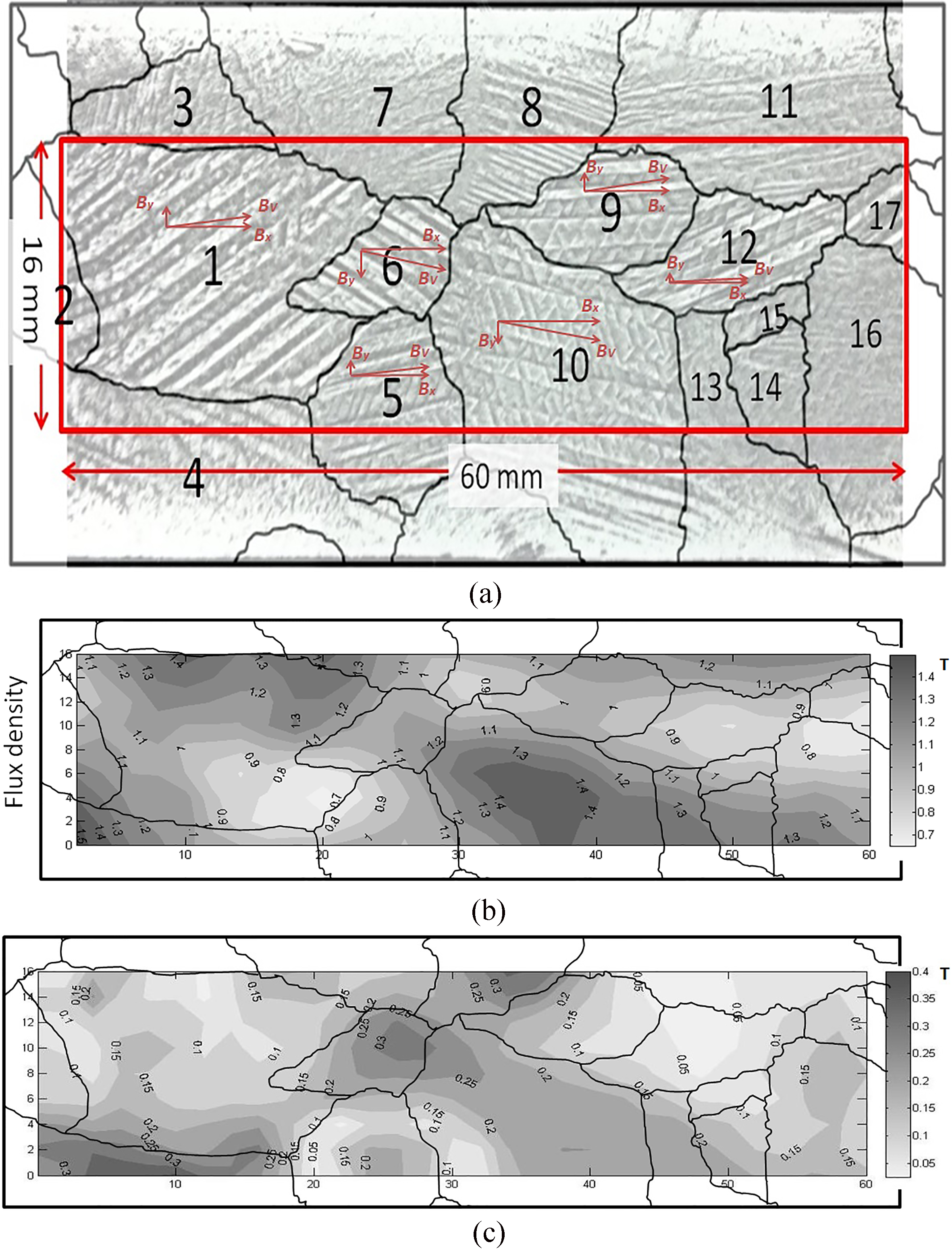
It is also found that when the same strip of poorly oriented steel is magnetised in a DC field that domains in different grains are activated at different field levels. For example domains in grain 8 begin to contribute to the overall magnetisation at around 0.7 T whereas domains in grain 1 do not begin to contribute until 1.2 T [8].
It may be argued that the loss due to the transverse components of field and flux density is included in the excess loss component in Eq. (1) but clearly it is not quantified or its physical nature is not accounted for. The diffusion equation applies within individual grains but its true effect and implementation is not understood. It can be further argued that equations such as Eq. (3) commonly used to solve 2-D magnetisation problems are somewhat different from the diffusion equation hence subject to greater errors. If this is the case our understanding of the basic magnetisation and loss mechanisms in GO steel is still superficial and perhaps wrong.
An implication of these transverse components in loss measurements is that the use of field sensors and loss computations based on the diffusion equation should be reviewed. Even if there effects are negligible under normal circumstances, their existence should be recognised. No steels have far more complex domain structures than GO steel so it is possible that transverse components can occur in a similar way within the individual grains. The extent to which this might affect measurements on both types of material using dB/dt and
(a) Two ways of assembling strips cut at an angle to the RD in the Epstein frame. (b) Variation of loss measured in strips cut at various angles to the RD using different stacking methods at 0.8 T, 1.2 T and 1.6 T.
There is often a call for measurement of losses in GO steel under unidirectional magnetisation at a fixed angle to the RD. It is not widely appreciated that the method in which strips are stacked in an Epstein frame to carry out such measurements affects the result. Figure 5 shows the result of testing strips cut at angles to the RD in an Epstein frame [9]. In practice the effect is found to be greatest in high permeability steels. The loss using the (a) type stacking gives results closest to values measured on single strips whereas the (c) type stacking gives results closest to completely random stacking. The reason for the difference in measured loss using the different stacking methods is probably partly due to the fact that demagnetising fields referred to earlier can affect the magnitude and direction of localised
Local deviation of magnetic field and flux density from the axis of a strip of GO steel cut at 45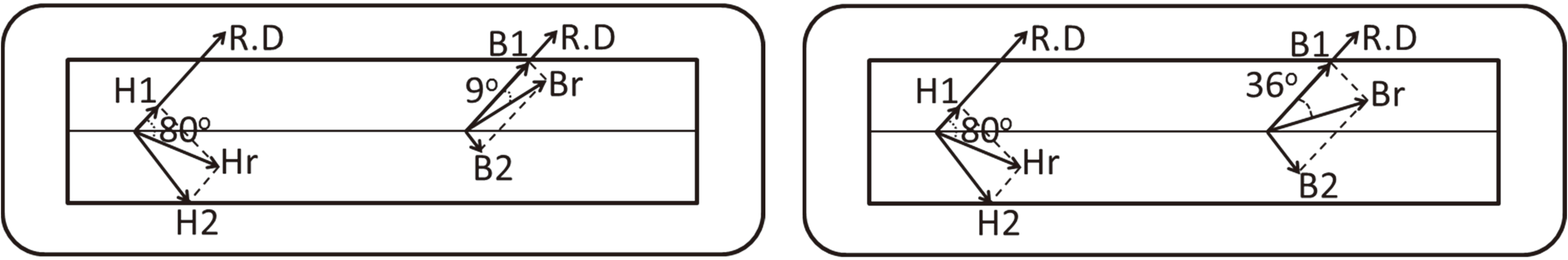
When single strips of GO steel are cut and magnetised at angles to the RD, magnetisation occurs based on the process depicted in Fig. 2b. The strip is cut at angle
Clearly when magnetising single strips of GO steel cut at angles to the RD, the direction and magnitude of the flux density and field varies in a complex manner according the nominal flux density so loss measurement needs careful interpretation. Furthermore the results of such tests are likely to vary with the geometrical aspect ratio of the strips. Conflicting findings on this aspect of the measurements have been reported so further clarification and quantification of the mechanism is needed. It is fortunate that the effect is expected to become far less significant at high flux density but the author is not aware of any published experimental or other verification that this is the case.
Circular (or pure) rotational flux density in a sheet of electrical steel refers simply to the situation when the flux is of constant magnitude rotates at a constant angular velocity in the plane of a sheet. To obtain this condition in the laboratory, often a sheet of electrical steel is magnetised using orthogonal magnetising coils in which the magnitude and phase of the currents are controlled such that the voltage outputs. dB(t)/dt , of orthogonal search coils vary sinusoidally with time, have the same peak value and are 90
Domain structure on the surface of a sheet of GO steel subjected to a slow (DC) rotational magnetic field when the flux density is at (a) 0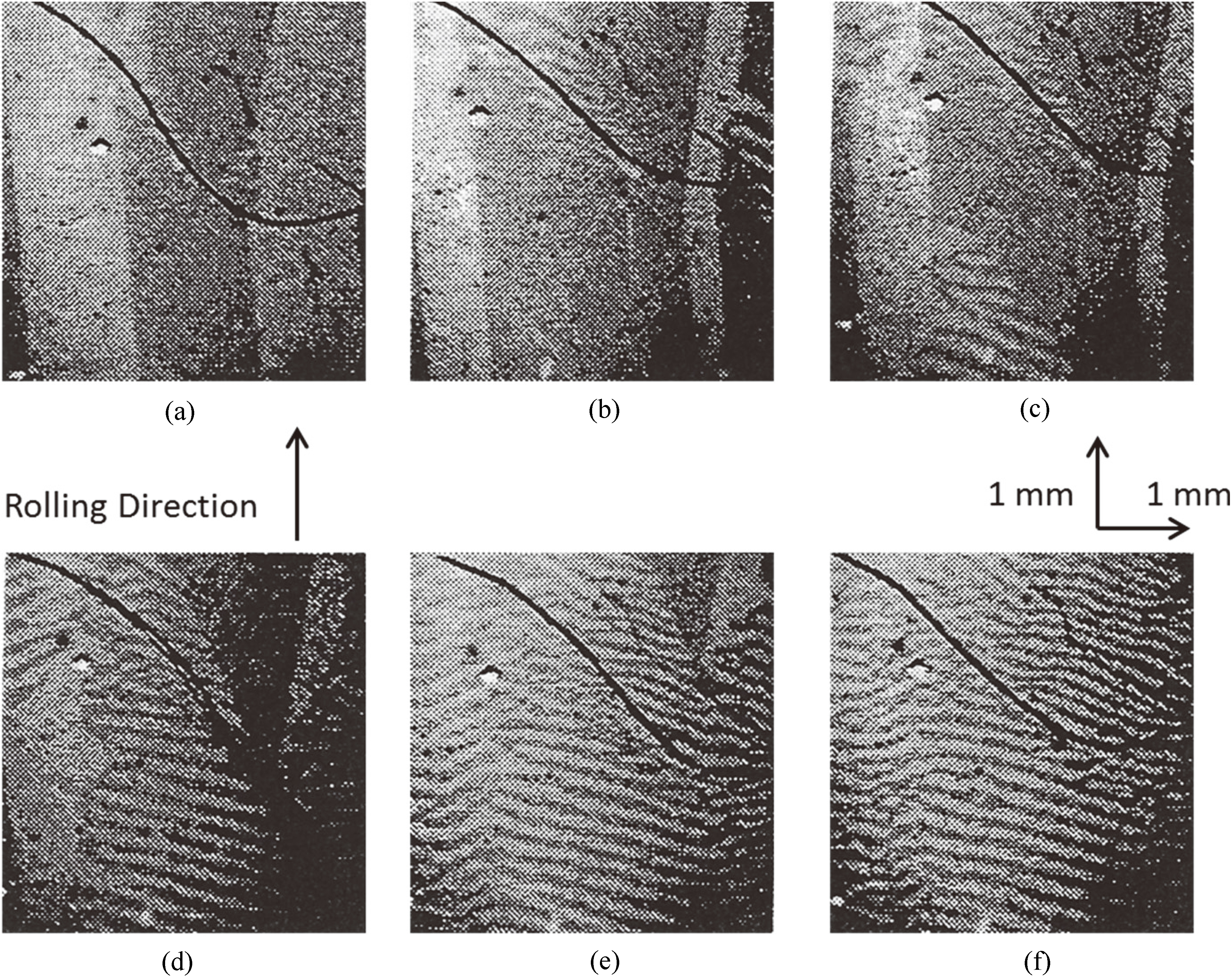
Simple vector representation of clockwise rotational magnetisation in a perfectly oriented crystal of GO at instances when flux density is along (a) [001] (OA) (b) [110] (OC) and (c) at angle 
Such circular magnetisation is usually set up as a convenient reference for comparing rotational losses of materials under known magnetising conditions. However it is questionable whether such conditions are actually achievable in practice in GO steel even when the voltage outputs of search coils satisfy the condition given in the previous paragraph. because of its complex domain structure and large magnetocrystalline anisotropy. Figure 7 [12] gives an indication of the complex changes in the domain structure observed on the surface of a grain in sheet of GO steel when subjected to a slowing rotating (DC) field. At the instant when the field is applied along the RD, typical slab domains are present directed along the [001] axis of the grain as expected. (The curved line in the photograph is part of a search coil which should be ignored). When the flux density has rotated to 25
A schematic vector representation of the rotational process is given in Fig. 8. If the field is rotating slowly in a clockwise direction, initially the flux density OA is along the [001] direction of the crystal and the driving field
Hence it can be seen from these domain structures that when the measured resultant flux density is at an angle
It is useful to briefly consider a frequently quoted basic expression for the rotational hysteresis loss in a sheet given as
where
Electrical steels are being increasingly used under severe flux harmonic distortion conditions. Waveforms containing up to the 50
where where
Today the more common way of analysis is simply to sum the instantaneous values of
This paper covers the presentation made at the 1 and 2 DM Workshop with the intention of provoking and stimulating discussion of the influence of microstructure in GO steel on some established measurement and performance prediction methods based on ideal magnetic theory. In practice microstructure and domain dynamics do have a large influence on losses particularly under rotational conditions and their effects are neglected or not properly quantified in many traditional approaches which cannot deal with modern material and the wide ranges of magnetisation conditions they experience in practice today.
The effect of ignoring them has not been quantified, it might be trivial in some cases, but unexpectedly large in others. However at present we do not have any better approach so we still need to attempt solutions based on Maxwell’s equations adapted to suit GO steel where possible, but it is important to be more aware of the possible errors this brings.