
Abstract
One of the major safety issues in nuclear power plants is pipe wall thinning where the pipe is mainly of magnetic material. Due to the large magnetic relative permeability of piping and the skin depth effect, the conventional PECT method is difficult for detecting the opposite side wall thinning. In this study, a pulsed eddy current testing (PECT) method under magnetic saturation was proposed and validated through numerical simulations and experiments. First, the mechanism of how magnetic saturation can increase the skin depth was studied through numerical simulation with help of COMSOL Multiphysics software. Second, the detection sensitivity of magnetic field signal and voltage signal for wall thinning defect of specimens with various magnetic permeability was investigated through numerical simulation. Finally, the experiments of magnetic saturation PECT were conducted, and the feasibility and superiority of the proposed magnetic saturation PECT method were demonstrated.
Keywords
Introduction
In nuclear power plants (NPPs), periodic non-destructive testing (NDT) is important to guarantee the structural integrity. Wall thinning is one type of pipe defect caused by flow accelerated corrosion and/or liquid droplet impingement of the coolant inside the pipe. A widespread material utilized in the piping of NPP is carbon steels [1, 2, 3, 4, 5]. Recently, many studies have been done to deal with the wall thinning NDT in carbon steel piping, but satisfactory results still have not been obtained [6, 7, 8]. PECT (pulsed eddy current testing) method has received a great deal of interest to solve this problem [9, 10, 11]. However, the large permeability of carbon steel seriously limits the detectability of the PECT method for piping of carbon steel. Fortunately, magnetic saturation could be an efficient way to help reduce the relative permeability of carbon steel and then possibly enhance the detectability [12]. However, the mechanism of how the magnetic saturation can increase the skin depth is still unclear. In addition, the feasibility of the PECT method under magnetic saturation has not been clarified.
Based on the backgrounds above, the objective of this study is to propose and validate the magnetic saturation PECT method for evaluating wall thinning defect in ferromagnetic material through numerical simulations and experiments.
Mechanism of magnetic saturation for enhancement of skin depth
In order to understand the mechanism how magnetic saturation can increase the skin depth, numerical simulations of magnetic field and eddy current field in a disc of two different magnetic materials status (
The disc is of 80 mm radius and 20 mm thickness. The excitation coil is of two current loops with a cross-section of circle of 2.5 mm radius, and the outside diameter of these two current loops are 12.5 mm and 18.5 mm, respectively. The excitation current injected into the coil is of sinusoidal wave and the excitation frequency is 100 Hz. The magnetic flux density and eddy current density under two different permeabilities are obtained, and the results are shown in Fig. 1.
Simulation results of single frequency ECT of 100 Hz excitation, (a) Distribution of magnetic field and eddy current when 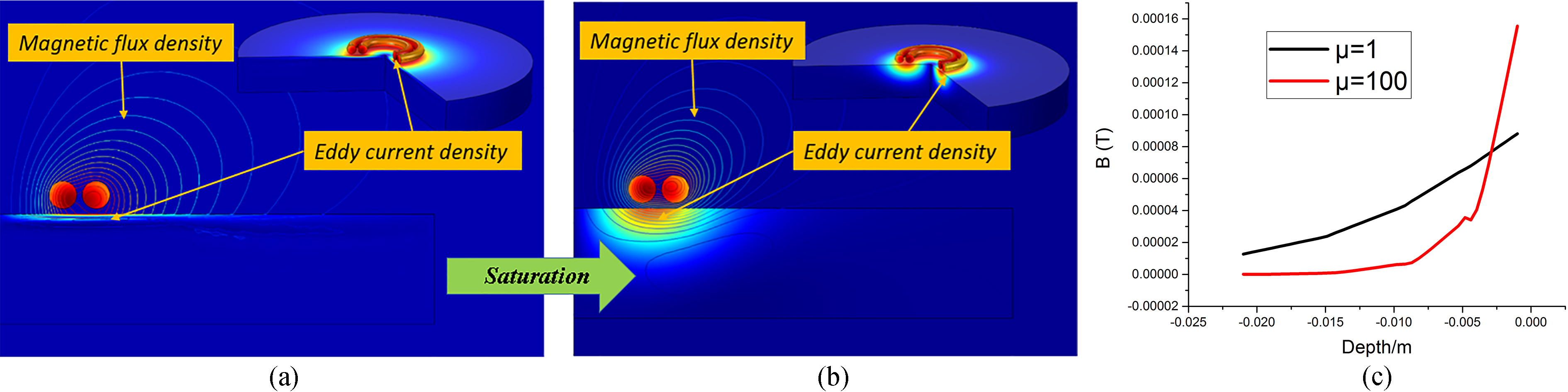
From Fig. 1, it can be found that both the magnetic flux density and the eddy current inside the conductor decay more slowly in the depth direction for a smaller permeability. Because the properties of two kinds of material are the same except the relative permeability, this means that reducing the relative permeability is an efficient way to increase the skin depth of eddy current for conventional single frequency ECT. On the other hand, as the pulsed excitation signal of PECT is a linear summation of the sinusoidal harmonic components [16, 17, 18] from the viewpoint of the Fourier transformation, the skin depth of PECT method can also be enlarged by reducing the magnetic permeability. As the permeability under magnetic saturation state is much smaller than the initial permeability, there is a good possibility for the PECT under magnetic saturation state to improve the detectability of wall thinning defect in opposite side for the carbon steel plate.
Simulation model and excitation current signal. (a) Simulation model; (b) Excitation current signal.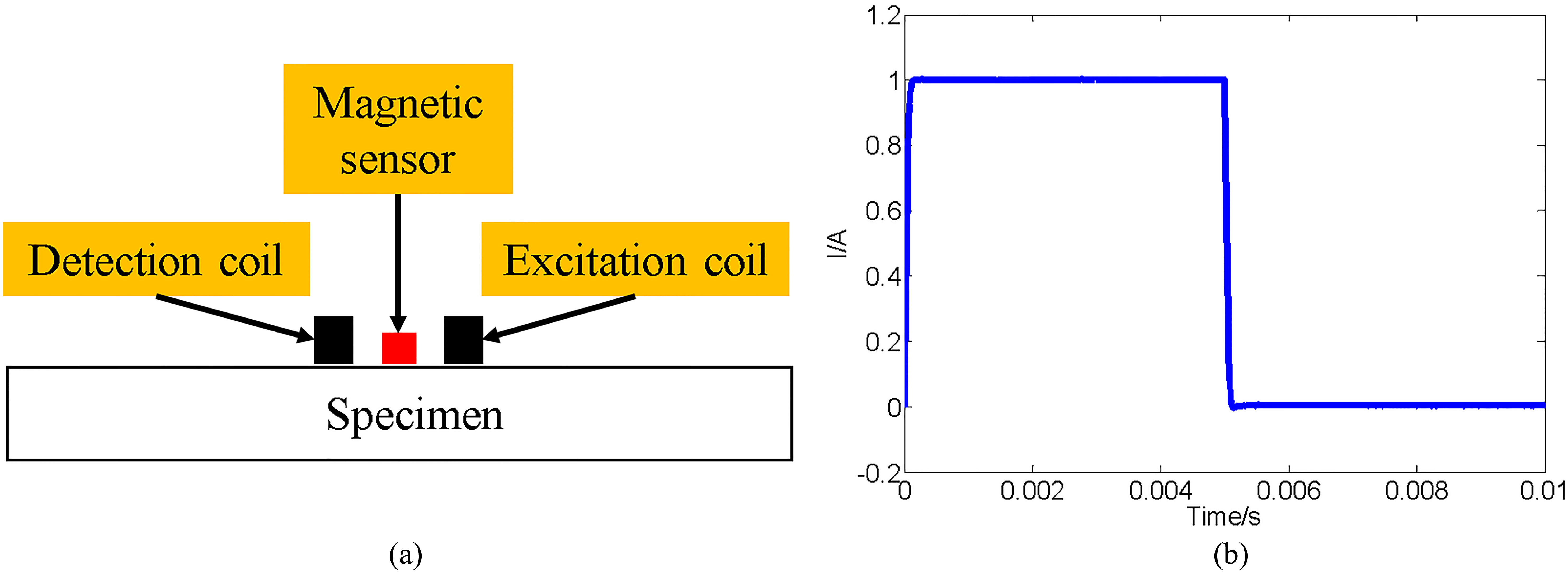
Magnetic field signals of different relative permeability and different thickness of plate specimen. (a) 
In order to know whether the PECT method under magnetic saturation can improve the detectability for ferromagnetic material, numerical simulation of PECT signals due to wall thinning defect under various magnetic relative permeabilities were carried out by using the COMSOL Multiphysics software and the numerical model is shown in Fig. 2a. Both the magnetic field at the center point of the probe measured by the magnetic sensor shown in Fig. 2a and the pickup voltage of the detection coil shown in the Fig. 2a were simulated. In practice, the PECT signals of four plate specimens with length 160 mm, width 160 mm and thickness of 1 mm, 2 mm, 3 mm, 4 mm respectively were simulated for different magnetic relative permeability. The difference of signals of different wall thickness reveals the global wall thinning defect signal. The dimensions of the excitation coil are outer diameter 10 mm, inner diameter 5 mm, height 5 mm and of 179 number of turns. The excitation current is of a square wave pulse with repetitive frequency 100 Hz and duty 50% as shown in Fig. 2b. The dimensions of the detection coil are the same with the exciter but of 2300 number of turns. The distance between the centers of the excitation coil and detection coil is 35 mm. The detection magnetic field signal and voltage signal for magnetic relative permeability of 1, 10, 50, 100 were calculated respectively.
Dependence of PECT peak signal on the global wall thinning.
The comparison of the numerical results of the magnetic field detection signals measured by magnetic sensor for different relative permeability are shown in Fig. 3. One can see that the signals due to wall thickness changes, i.e., the global wall thinning signals show significant difference for different magnetic permeability. Figure 4 gives the dependence of differential wall thinning signal peaks on the residual wall thickness for different magnetic permeability. One can find that the PECT signals show higher sensitivity to wall thinning depth for a lower magnetic permeability (blue line with triangle points). This means that the detectability of PECT can be improved when the testing specimen was magnetic saturated as its permeability becomes smaller. On the other hand, Fig. 4 also shows that the PECT signal peak of 100 relative permeability is near limited for the 4 mm thickness plate, but the PECT signal is almost linearly increasing with plate thickness for case of unit relative permeability. This means that maximum wall thickness to be detected can be efficiently enlarged by reducing the permeability, i.e., magnetic saturation is efficient to improve the detectability of PECT method for ferromagnetic material.
Voltage signals of different relative permeability and different thickness of plate specimen. (a) 
Differential voltage signals of different relative permeability and different thickness of plate specimen (reference signal: 4 mm PECT signal). (a) 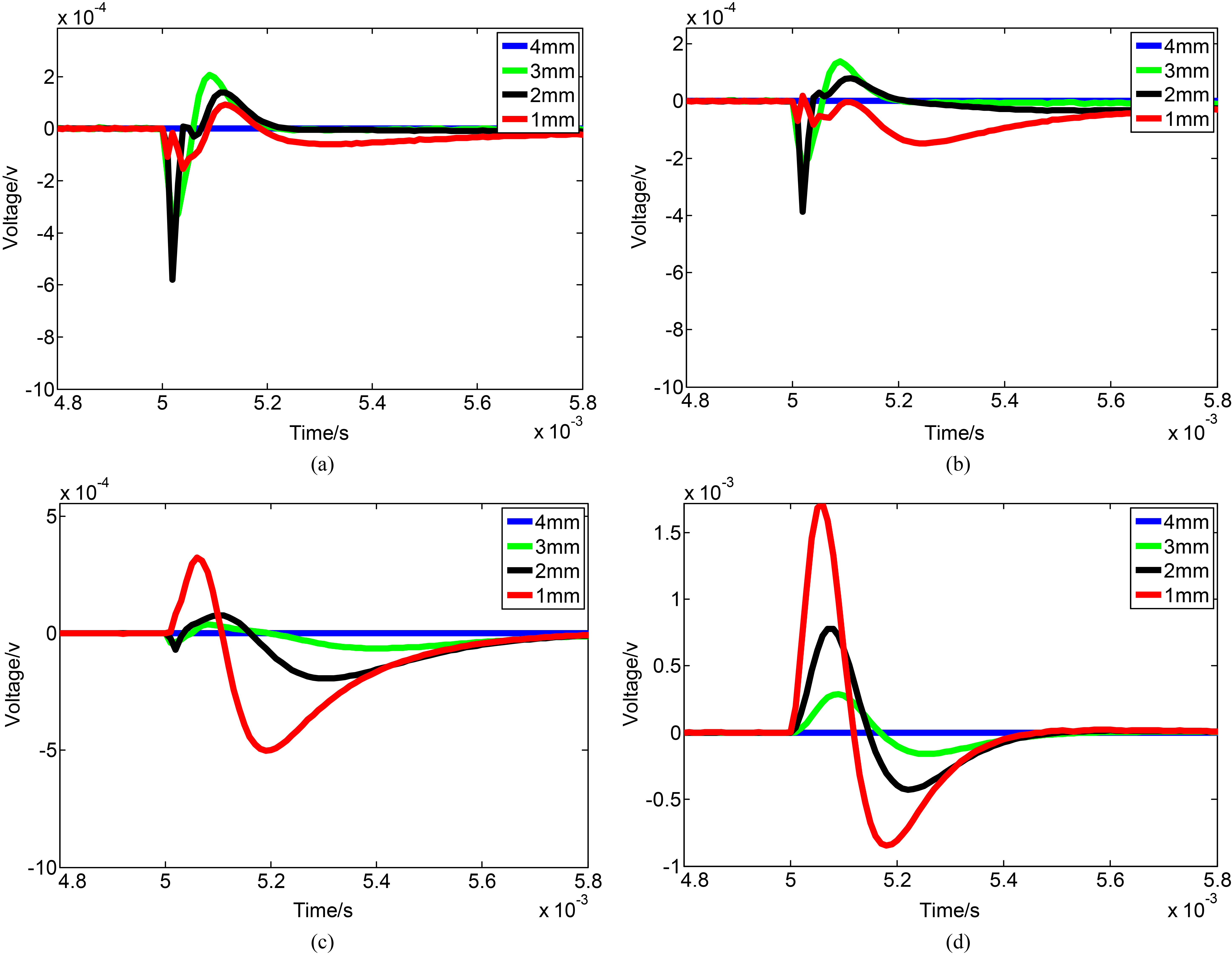
Peak value of differential voltage signals.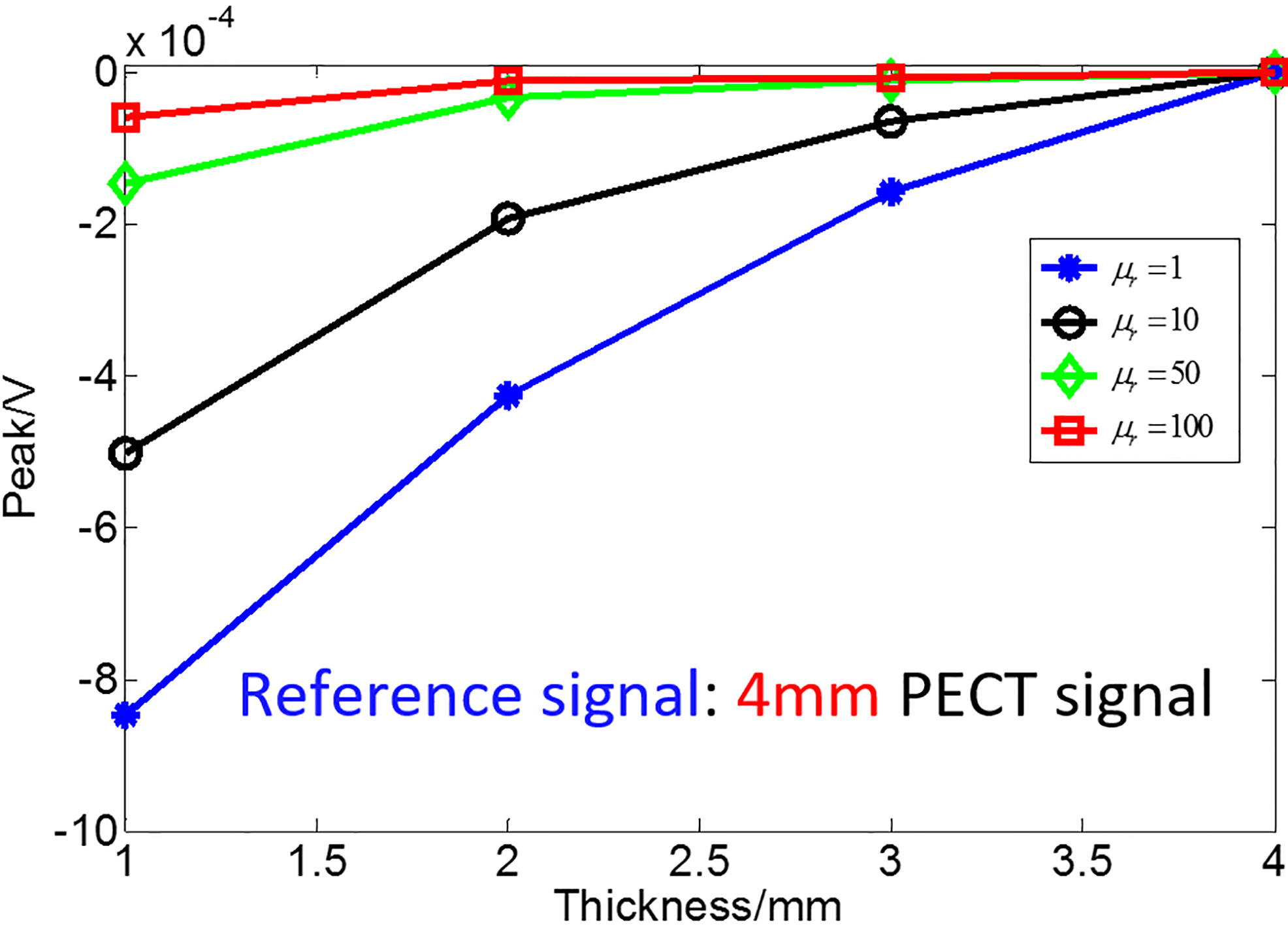
Experiment environment, (a) Electromagnet for generating external saturation magnetic field; (b) Magnetic saturation PECT experiment setup; (c) PECT experiment setup part.
Specimen, PECT probe, fixture and excitation current. (a) Specimen, PECT probe and fixture; (b) Excitation current signal.
Thereafter, the voltage signals of detection coil for different relative permeability are as those shown in Fig. 5. It can be found that, when the relative permeability becomes smaller the detection voltage signals of different thickness plate are of more differentiable. The reason is that voltage signal is time derivative of magnetic field, and the magnetic flux density inside the conductor decays more slowly in the depth direction for a smaller permeability mentioned in part 2. Therefore, the more differentiable of the magnetic flux density in the depth direction leads to the more differentiable of the voltage signals in the depth direction.
Meanwhile the differential voltage signal of different thickness plate can be obtained which the reference signal is PECT signal of 4 mm thickness plate, the result is shown in Fig. 6. To further characterize the influence of the magnetic permeability on the PECT detectability, the dependence of peak values of the voltage signals are extracted and illustrated in Fig. 7 for different permeabilities. From Fig. 7, it is clear that the PECT method with voltage pickup signal using detection coil is difficult to detect wall thinning defect in a plate of thickness over 1 mm and of relative permeability more than 100. However, when the relative permeability is reduced to 1, i.e., to nonmagnetic state, there is clear difference between signals of 3 mm and 4 mm wall thickness. This indicates that maximum plate thickness capable to be inspected by using the PECT method with voltage pickup signal can be more significantly improved under the magnetic saturation strategy. However, comparing with Fig. 4, it can also be concluded that the PECT using magnetic sensor is more suitable for detecting wall thinning defect in thick plate than by using detection coil.
In order to validate the proposed PECT method under magnetic saturation and simulation model, the experiments of PECT method under magnetic saturation were conducted. The feasibility of the proposed and developed PECT method under magnetic saturation are demonstrated.
Experiment setup of magnetic saturation PECT
The experiment environment is shown in Fig. 8. Magnetic saturation PECT experiment setup includes two parts, which is shown in Fig. 8b. One is the PECT experiment setup part shown in Fig. 8c and it mainly includes function generation, power amplifier and differential amplifier, analysis software and probe. The probe consists of excitation coil and detection coil, shown in Fig. 9a. The dimensions of the excitation coil and detection coil are completely the same as in simulation model. The excitation current is square wave with repetitive frequency of 100 Hz and duty 50%, which is shown in Fig. 9b. The distance between the centers of excitation coil and detection coil is 35 mm. The other part is a pair of large electromagnet for generating external saturation magnetic field, which is shown in Fig. 8a. The current injected to the coil of electromagnet can reach to 160 A, with the minimum distance of 100.9 mm between the top coil and the bottom coil, the maximum magnetic flux density in the center of this pair of electromagnet can be 1.6 T.
Experiment results and discussions
The Q345B (the composition is shown in Table 1) plate specimens with different thickness of 1 mm, 2 mm, 3 mm, and 4 mm are employed in this study as shown in Fig. 10a. Both of the width and length of the plate are 160 mm. The virgin magnetization curve of this material can be measured by experiment [19]. The result is shown in Fig. 10b.
Composition of Q345B
Composition of Q345B
Specimens and its magnetic properies. (a) Q345B plate specimens; (b) Initial magnetization curve.
Experiment results of voltage signals. (a) External magnetic flux density 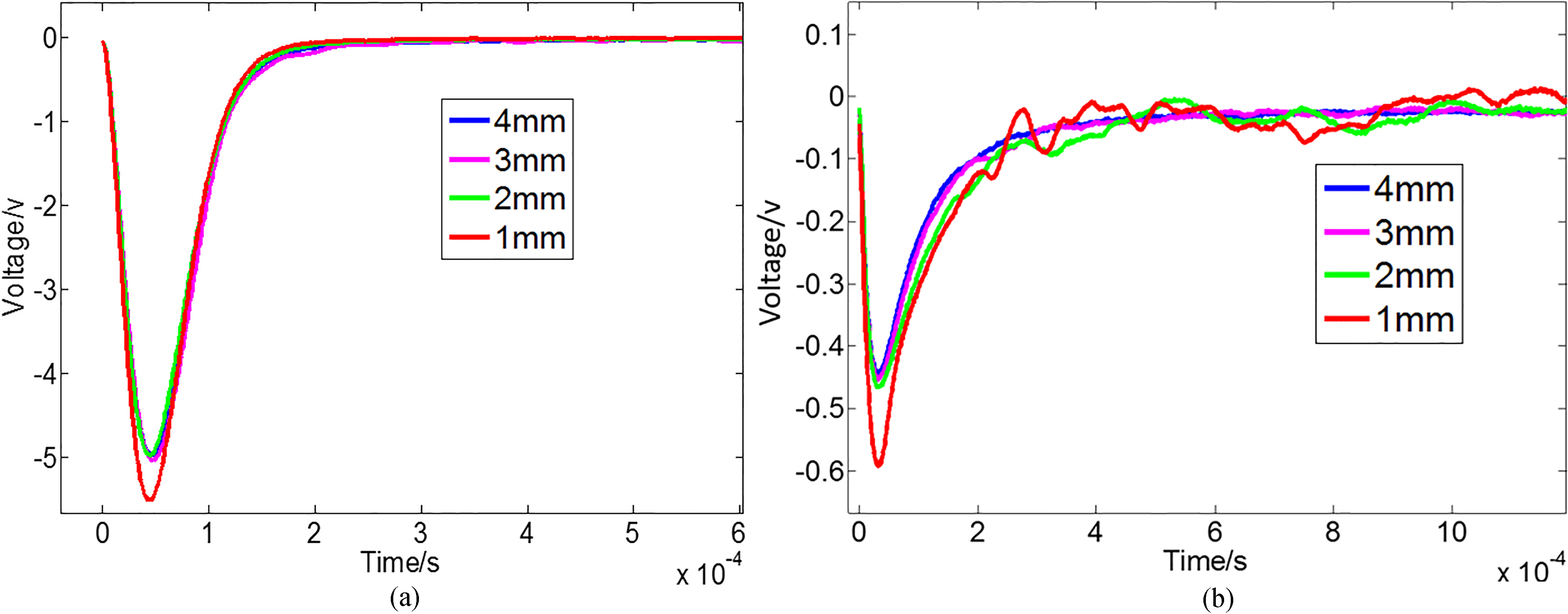
Normalized peak value of experimental voltage signals.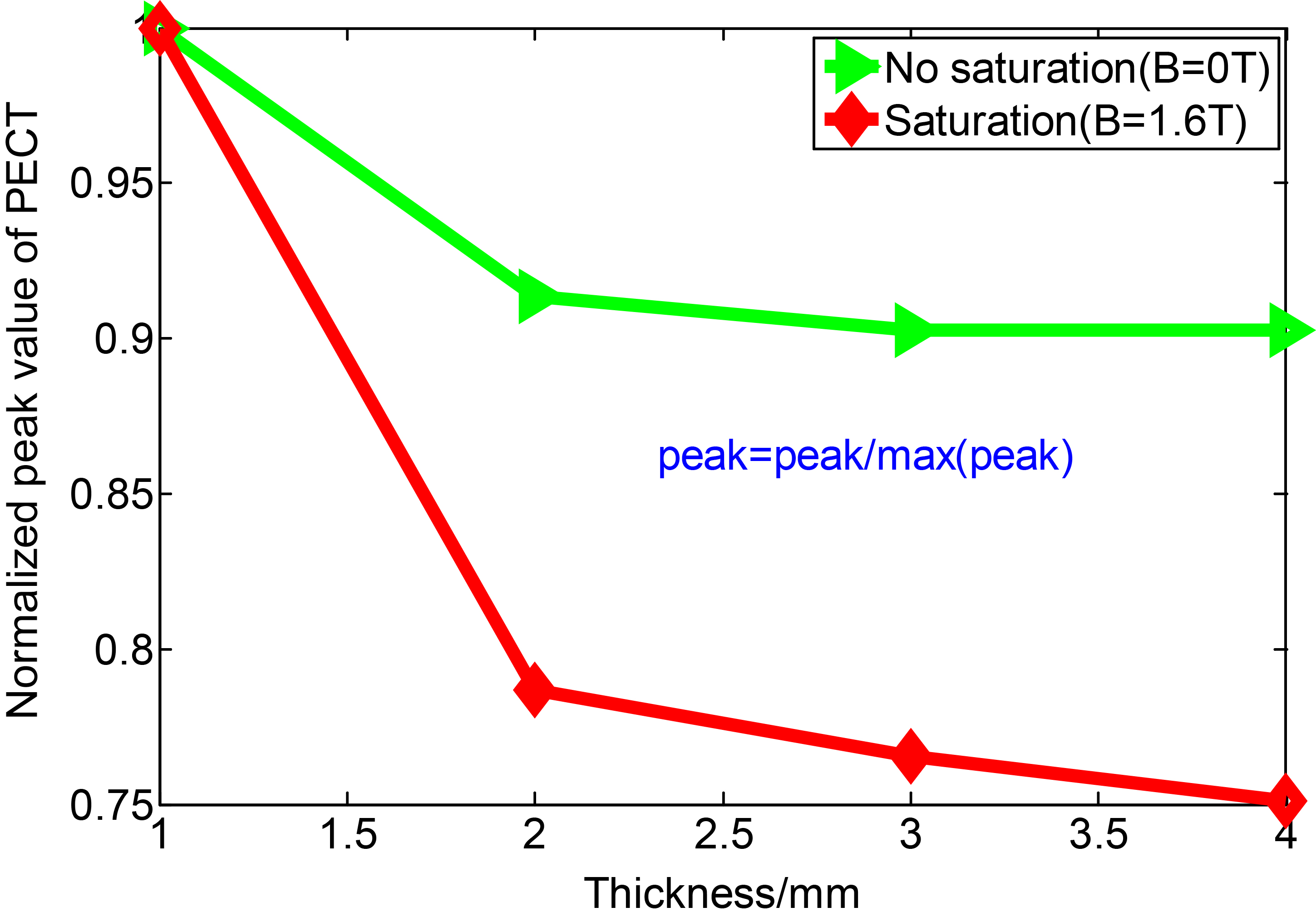
Normalized detection sensitivity of PECT voltage signals.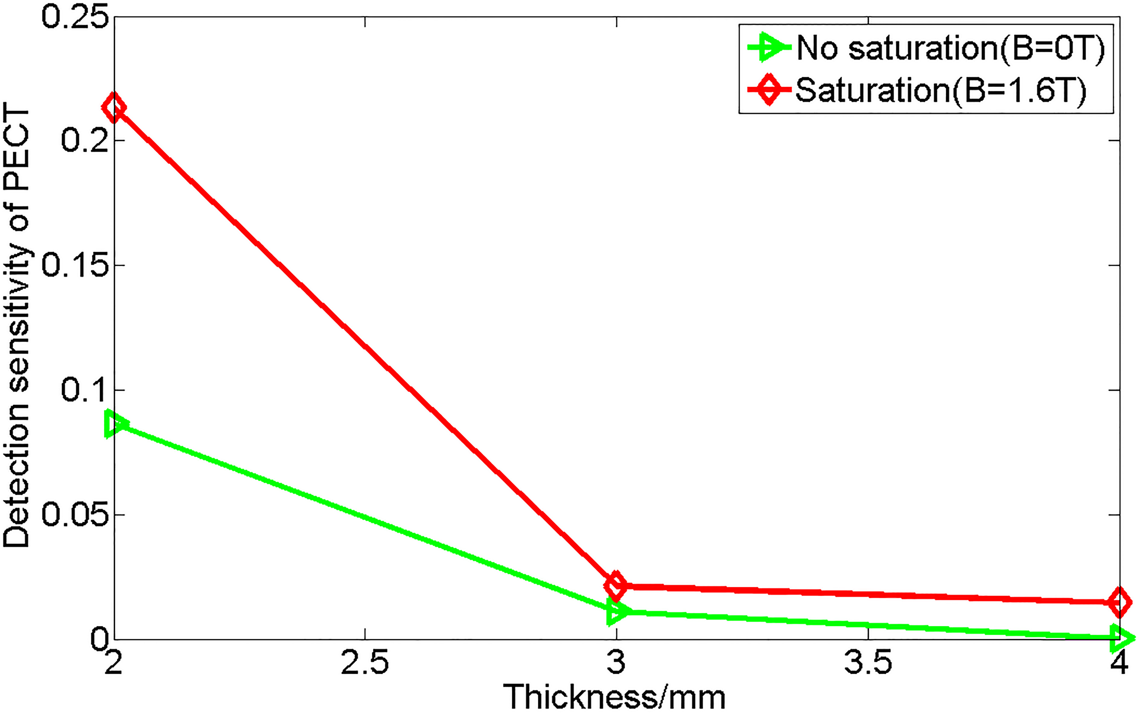
Two cases of PECT experiment have been carried out under situation of that external magnetic flux density B equals 0 T and 1.6 T, respectively. That B equals 0 T means there is no external magnet added, so the relative permeability of specimen is still very large; that B equals 1.6 T means the specimen is approximately under saturation and the relative permeability of specimen is lower than initial one. The above detection voltage signals for different thickness plate are measured and compared. The results are shown in Fig. 11. It can be found that when the external magnetic field is 1.6 T (the relative permeability can be reduced to less than 50, lower than initial permeability), the detection voltage signals of different thickness plate are of more differentiable. To further characterize the PECT detectability for different condition and different thickness plate, the peak values of experiment signals are extracted and then normalized. The result is shown in Fig. 12. In addition the normalized sensitivity of the PECT under different magnetic condition can be obtained and compared, where the normalized sensitivity is determined by the formulae of
A magnetic saturation PECT method was proposed for detecting opposite side wall thinning defect in a thick ferromagnetic plate. First, the mechanism of how the magnetic saturation can increase the skin depth was investigated. Second, numerical simulations of PECT signals were conducted for different wall thinning and different magnetic permeability, and the results show that reducing the magnetic permeability can significantly improve the detectability of PECT for ferromagnetic plate. In addition, experiment of magnetic saturated PECT was carried out. The feasibility of the proposed magnetic saturation PECT method was demonstrated experimentally for application to wall thinning defect in plate of ferromagnetic material.
Footnotes
Acknowledgments
The authors would like to thank the National Magnetic Confinement Fusion Program of China (No. 2013GB113005), the Natural Science Foundation of China (No. 51407132, 51277139, 51577139) for funding. This work was partly supported by the Fundamental Research Funds for the Central Universities and the JSPS Core-to-Core Program, A. Advanced Research Networks, “International research core on smart layered materials and structures for energy saving”.