
Abstract
This paper presents an electromagnetic testing method for moisture separator reheater (MSR) tubes, which is based on partial saturation eddy current testing (PSECT). The sensor probe has a permanent magnet that is used to partially saturate the MSR tube material, a bobbin coil is used to supply an alternating electromagnetic field that penetrates into the tube, and a bobbin-type integrated Hall sensor (BIHaS) array is used to measure the radial component of the electromagnetic field distribution in the tube. The BIHaS has 15 Hall sensor elements arrayed at 24
Keywords
Introduction
The moisture separator reheater (MSR) system is set up between the high pressure (HP) and low pressure (LP) steam turbines in a pressurized-water nuclear power plant. The MSR is usually composed of finned tubes that have about three times the surface area of un-finned tubes. The MSR removes moisture and reheats the cycle steam to protect the LP turbine blades from erosion and corrosion and improve the thermodynamic efficiency of the LP turbines [1]. In the past, the MSR tube was made of 90-10 CuNi, but this has been replaced by ferritic stainless steel (SS439), a ferromagnetic material that is stronger and has excellent corrosion resistance [2]. However, after long-term operation, the erosion and corrosion can appear on the outer surface of the MSR tubes [2, 3]. The failure of the MSR tubes could stop the operation of the nuclear power plant. Thus, nondestructive testing is required to inspect the damage at an early stage.
Ultrasonic testing (UT) systems using guided waves have been developed for inspection of MSR tubes [4]. However, the UT system requires a coupling material between the guide wave and tube surface that is difficult to maintain during inspection. Electromagnetic testing is a preferred technique, and both magnetic flux leakage testing (MFLT) and eddy current testing (ECT) have been successfully used for inspection of tubes with no requirement for coupling material [5, 6, 7, 8, 9]. MFLT is used for inspection of ferromagnetic material by measuring the magnetic flux leakage around the damage [5, 6]. However, it is limited in a finned tube because the fins produce a high level of noise. ECT can be applied for both ferromagnetic and paramagnetic materials [7, 9], but it is difficult for an electromagnetic field to penetrate into ferromagnetic material targets because the high permeability of the material prevents deep penetration of the eddy current. Remote field eddy current testing (RFECT), in which the sensing coil is placed far from the exciting coil (2–3 times of the inner diameter of the tube), is an efficient method for inspection of ferromagnetic material [10]. RFECT is equally sensitive to inner and outer diameter damages, so they could not be distinguished. Therefore, full/partial magnetic saturation of the tube material is performed to reduce the permeability, and then the ECT technique can be applied; this is called full/partial saturation eddy current testing (FSECT/PSECT). A sample partial saturation is shown in Fig. 1. This is finite simulation result by ANSYS software for a static magnetic field distribution in a ferromagnetic tube produced by a permanent magnet. The material under the defect was highly magnetized due to the loss of the material. To fully saturate the material, a strong permanent magnet or a coil with a high DC current is necessary, but it’s difficult in real applications. Conventional FSECT/PSECT systems use a sinusoidal wave current to supply the exciting coil [11, 12], but a pulse wave form has been recently used with more advantages by the mean of superposition of infinite frequencies [13]. However, the current FSECT/PSECT systems still have limited spatial resolution because of the use of a single/differential-type sensing coil.
Finite simulation results of magnetic field distribution in a ferromagnetic tube by a permanent magnet. The simulation was performed by ANSYS software.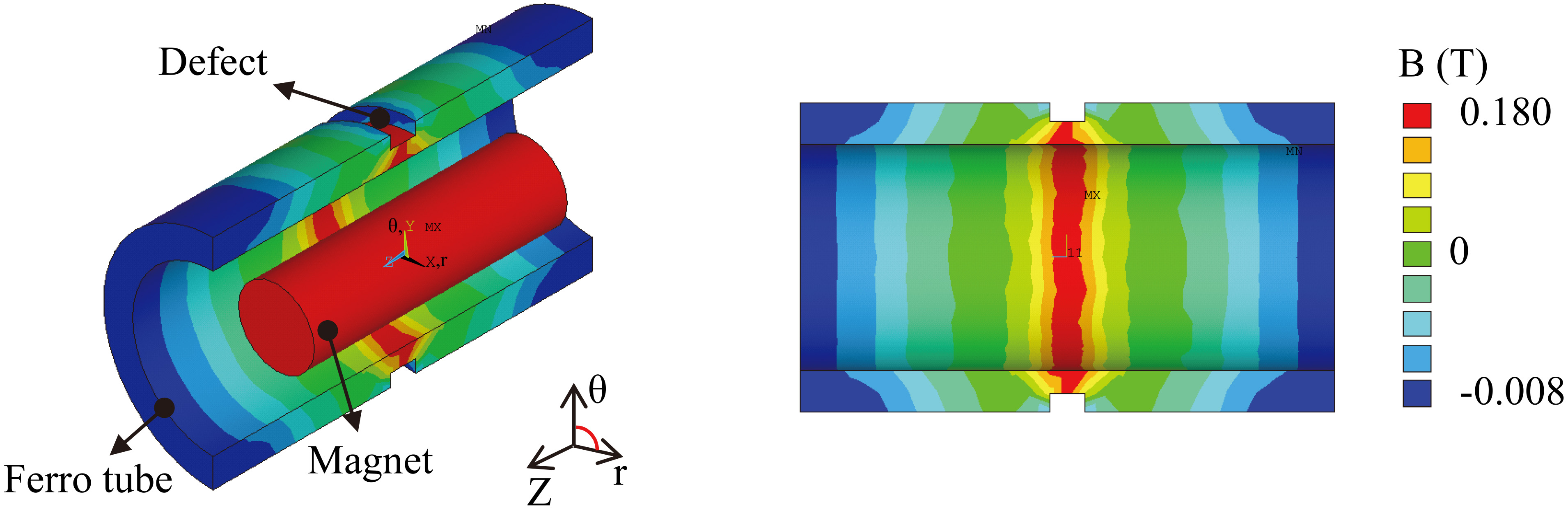
Therefore, this paper proposes a PSECT system using a bobbin-type integrated Hall sensor (BIHaS) array instead of a single/differential-type sensing coil as used in conventional PSECT systems. The BIHaS is composed of many Hall sensor elements arrayed in the circumferential direction of the probe so that the location of damage in the circumference of the MSR tube can be identified and a quantitative evaluation of damage size can be performed [14, 15]. The BIHaS is used in three inspection systems (MFLT, ECT and PSECT), and the advantages of the PSECT system over the MFLT and ECT systems are presented.
Figure 2 shows the three inspection techniques, which are MFLT (Fig. 2a), ECT (Fig. 2b), and PSECT (Fig. 2c), using a BIHaS. In MFLT, a permanent magnet is used to produce magnetic leakage around damage in the tube, the radial component of which is measured by the BIHaS [14, 15, 16]. In ECT, an exciting bobbin coil is used to produce eddy currents in the circumferential direction of the tube. If there is a damage in the tube, the eddy current will be distorted and concentrated around the damage. The radial component of the secondary magnetic field, which is induced from the eddy current, will be measured using the BIHaS. PSECT is a combination of the two techniques, in which a permanent magnet is used to partially saturate the tube material and a bobbin coil is used to produce the eddy current in the tube.
Three types of inspection technique using a bobbin-type integrated Hall sensor array: a) magnetic flux leakage testing (MFLT), b) eddy current testing (ECT), and c) partial saturation eddy current testing (PSECT).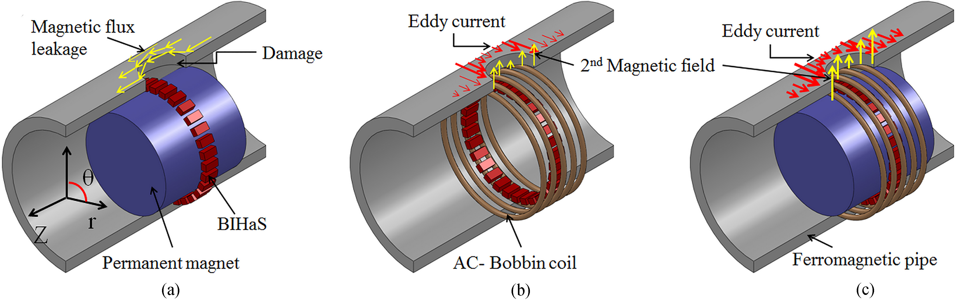
At certain scan speed of MFLT or ECT system; an extra induced current in conductive specimen is produced according to Lorentz’s Law and Lentz’ Law. This current makes a reduction of electromagnetic field of damage. Thus, the detectability of the system could be reduced at a high scan speed. Tian el at. observed in theirs research [17] that the magnetic field distribution around a crack was changed in pattern as well as intensity when the scan speed is about 36–108 km/h. However, at a low speed as using in this study, the effects could be ignored [18].
The output voltage of the BIHaS is processed using high-pass filters (in ECT and PSECT) or low-pass filters (in MFLT), differential-type amplifiers, root-mean-square-circuits for converting to DC signals (in ECT and PSECT) and through an AD converter to a computer.
Figure 3 shows the experimental setup of the three inspection systems. The BIHaS has 15 Hall sensor elements arrayed at 24
A ferritic stainless steel (SS439) MSR finned tube was used in the experiment. The inner diameter, outer diameter, and wall thickness (W.T) are 14.1, 19.1, and 1.2 mm (excluding fin height). The fin has a height of 1.3 mm and a step of 1.1 fins/mm. Artificial defects (flat-bottom hole) were produced on the outer surface of the pipe with depths from 10 to 100% of the W.T and diameters of 1.3, and 2.5 mm. The detailed defects sizes are shown in Table 1. The MSR tube was scanned at a speed of 28 mm/s and 1 mm/data interval. In addition, the attraction force between the permanent magnet and the MSR tube could make noise and damage to the sensor during scan. Thus, two centering parts have been attached at the front and end sides of the sensor probe, as shown in a picture sensor prototype in Fig. 3.
Sizes of defects on the MSR tube
Sizes of defects on the MSR tube
Experimental setup of the three inspection systems.
In experimental results, the differential (
where
Figure 4 shows the experimental results of MFLT (Fig. 4a), ECT (Fig. 4b), and PSECT (Fig. 4c). A current of 300 mA at 900 Hz was supplied to the bobbin coil in ECT and PSECT. In middle of defects #2 and #6, a high signal appeared due to the deformation of the specimen during the milling operation of defect #2. It can be observed that the MFLT result has the highest noise, which is mainly from the fins of the MSR tube. Thus, it is difficult for MFLT to detect small defects. It can detect a minimum size of 60% W.T depth – Ø1.3 (#6). The noise in the PSECT is slightly higher than in the ECT because the eddy current in the PSECT penetrates deeper into the wall thickness and approaches to the fins, and that produces higher noise. However, the intensity of the defect signal at each frequency in PSECT was significantly higher than that in the ECT. ECT can detect defects with 40% W.T depth – Ø1.3 (#7), and 20% W.T depth (#8) can be observed, but with low intensity. The PSECT provides the best detection probability, i.e., 20% W.T depth – Ø1.3 (#8) can be detected. It can be observed that the intensity of the defect signal increases as the defect size increases in all three inspection techniques. Thus, the evaluation of defect size can be performed. Furthermore, the locations of defects on the circumferential direction of the MSR tube can be observed.
Experimental results of defects on the MSR tube by a) MFLT, b) ECT with exciting current of 300 mA–900 Hz, and c) PSECT with exciting current of 300 mA–900 Hz.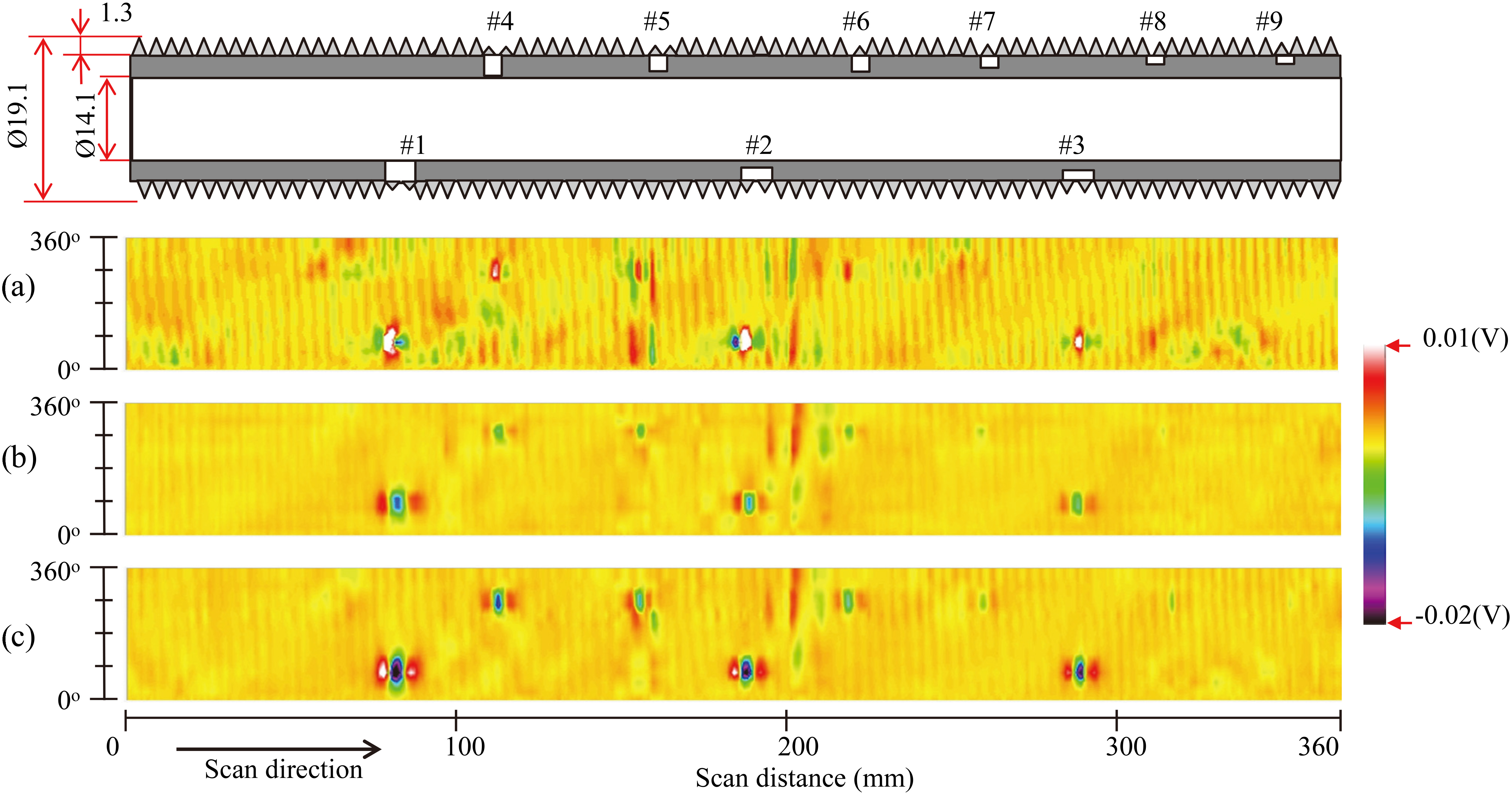
For quantitative evaluation of defect volume (Vol) for ECT and PSECT, the sum of the absolute defect area signal (
where
Evaluation of defect volume: a) linear relationship between sum of absolute defect area signal with defect volume at 900 Hz, b) sensitivity of defect area signal against exciting frequencies, and c) estimation of defect volume results at 900 Hz.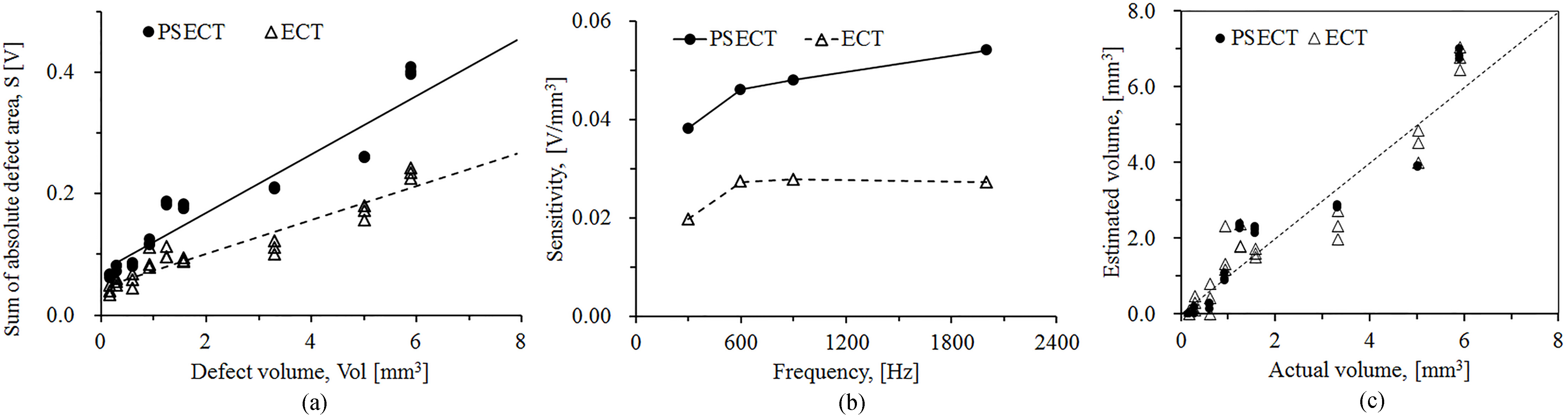
The “sensitivity”
This paper presents partial saturation eddy current testing (PSECT), a method of electromagnetic testing using a bobbin-type integrated Hall sensor (BIHaS) array. The BIHaS has 15 Hall sensor elements arrayed at 24
Footnotes
Acknowledgments
This research was funded by KEPCO Plant Engineering, and the Korea Institute of Energy Technology Evaluation and Planning (KETEP 20171520101610). We are grateful for the support.