
Abstract
In this paper we propose a procedure to design pulse generators for the simulation of lightning indirect effects in avionic systems. A genetic algorithm is used to identify the generator parameters for different strength levels to obtain high accuracy of the voltage and current waveforms in comparison to the international standards requirements. A dedicated experimental set-up is used to evaluate the accuracy and the effectiveness of the optimization procedure. Measured and computed data are compared and discussed.
Introduction
The use of electronic and electromechanical equipments to improve performances and comfort of aircrafts is rapidly increasing in these last years. Possible faults of these devices can be critical for the flight safety, therefore accurate design and qualification procedures have to be carried out to satisfy the functional requirements under different environmental conditions. A complete electromagnetic compatibility qualification is important, where several test are performed to evaluate the electromagnetic emissions and the susceptibility of the electronic and electromechanical equipments. A dedicate international standard was developed for this aim [1, 2]: in that document environmental conditions, instruments and procedures are discussed and specified, in order to perform the suitable electromagnetic compatibility tests. Among them one of the most critical is the so called indirect lightning test, where the effects on the electric power plant of an aircraft, after a lightning shot, are simulated. The standard procedure indicates different waveforms and amplitudes for the induced lightning pulses in order to simulate indirect lightning under different conditions. In addition the waveform requirements are changing in time with the successive standard revisions. For these reasons different lightning generators have to be used. In this paper we propose a design procedure for the lightning generators to optimize their performances. The papers presented in literature propose in general empirical formulas to obtain the generator network parameters [3, 4, 5, 6]. The validity of these formulas are limited to specific circuits. In our work we propose a more general approach, that can be used for different circuits of lightning generation tests. The procedure is based on a genetic algorithm to obtain the optimal values of the electrical parameters of the generator for a given waveform. The method was validated by a comparison between the experimental results and the standard waveform requirements.
Levels of waveforms 4 and 1
Levels of waveforms 4 and 1
Voltage and current waveform 1 and 4 of the section 22 of [1].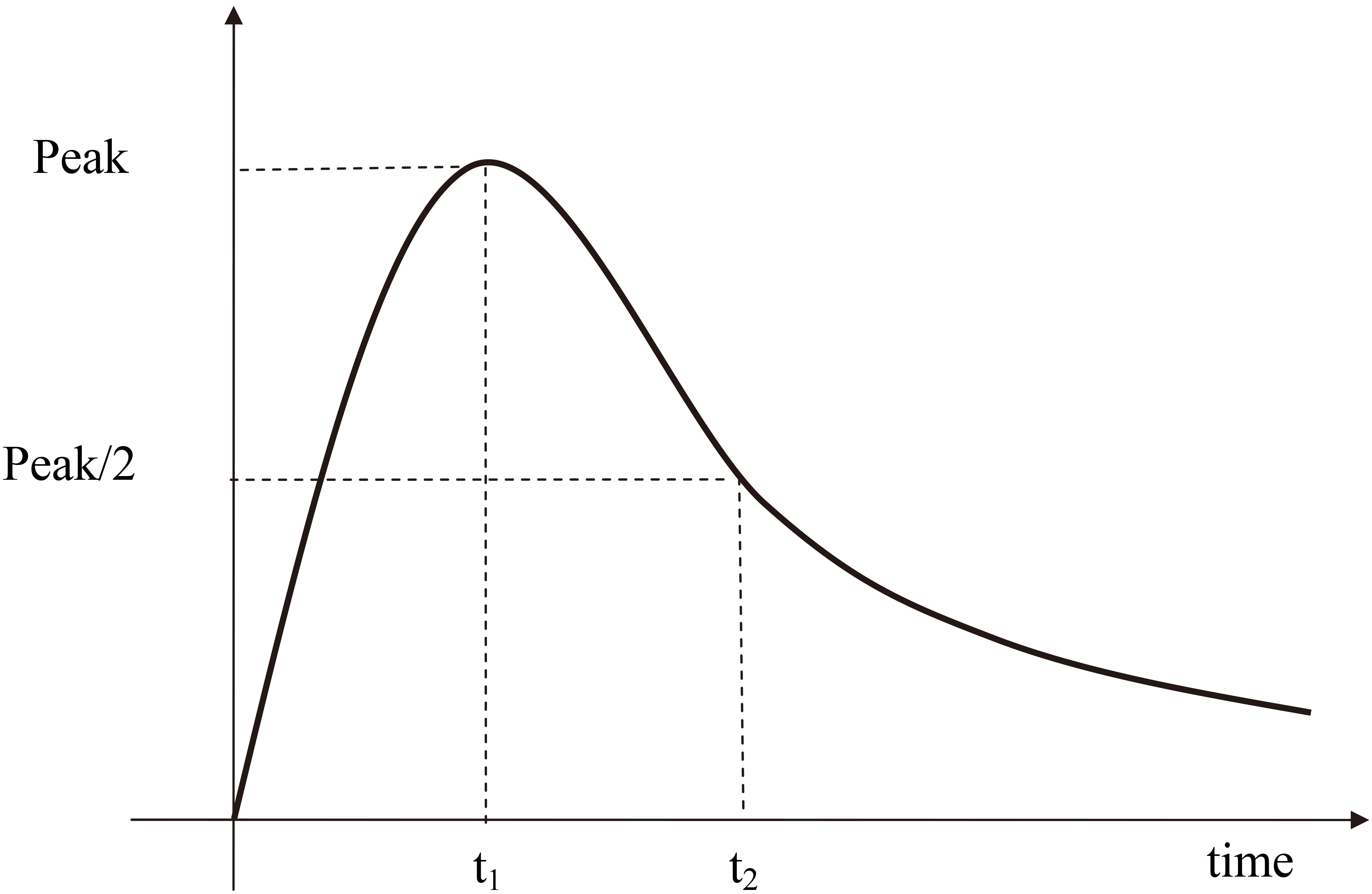
In this work we have considered the pin injection method and the waveforms 1 and 4 specified in the Section 22 of the standard [1]. Before the tests a calibration procedure have to be done, by reproducing these waveforms. We have defined an optimization procedure for the identification of the parameters of the lightning generator to be used in this case. The identification procedure can be easily extended to other injection methods and waveforms. The waveform 1 is the current waveform generated when the lightning generator is in short circuit condition (Isc), while the waveform 4 is the voltage waveform generated when the lightning generator is in open circuit condition (Voc). The typical waveform parameters are indicated in the Fig. 1. The value of the waveform level, the rise time and the fall time, in agreement with the standard [1], are reported in the Table 1. Different values of the waveform levels are specified for different positions of the equipment under test (EUT) inside the aircraft. The equipments placed close to the external structure of the aircraft have to be tested using the higher waveform levels, while the tests related to the equipments placed in the protected area are referred to the lower waveform levels.
During the pin injection test the injection of the lightning induced current is made directly into the pins of the EUT connector, in general between each pin and the case ground. This test is used for assessing the dielectric withstand and the damage tolerance of the equipment circuit interface.
Identification of the lightning generator parameters
The lightning generator is roughly made by three parts, an high voltage supply, a capacitor and an electrical coupling net to inject the induced transient into the EUT pins. The high voltage supply is used to charge the capacitor up to a given voltage level, after that the capacitor is discharged into the EUT pins trough the coupling net. The characteristics of the Voc and Isc waveforms are function of the parameters of the capacitor and the coupling net. Different kind of coupling net can be used; one of these is represented in Fig. 2. A DC high voltage supply is used to charge the capacitor C1 trough the switch S1 closed. When a given voltage level V0 is reached the switch S1 is open and the switch S2 is closed. In this way the energy stored in the capacitor C1 is discharged trough the right part of the circuit. The parameters V0, C1, L1, R1 and R2 have to be identified in order to obtain the waveforms 4 and 1 described in the previous section, using respectively the circuit configurations shown in Fig. 2a and b. A this point the indirect lightning test can be done using the parameters identified and the test set-up presented in Fig. 2c. Different test levels can be performed using different values of the parameter V0, keeping constant C1, L1, R1 and R2.
Lightning generator layout: (a) calibration set-up for the waveform 4; (b) calibration set-up for the waveform 1; (c) test set-up.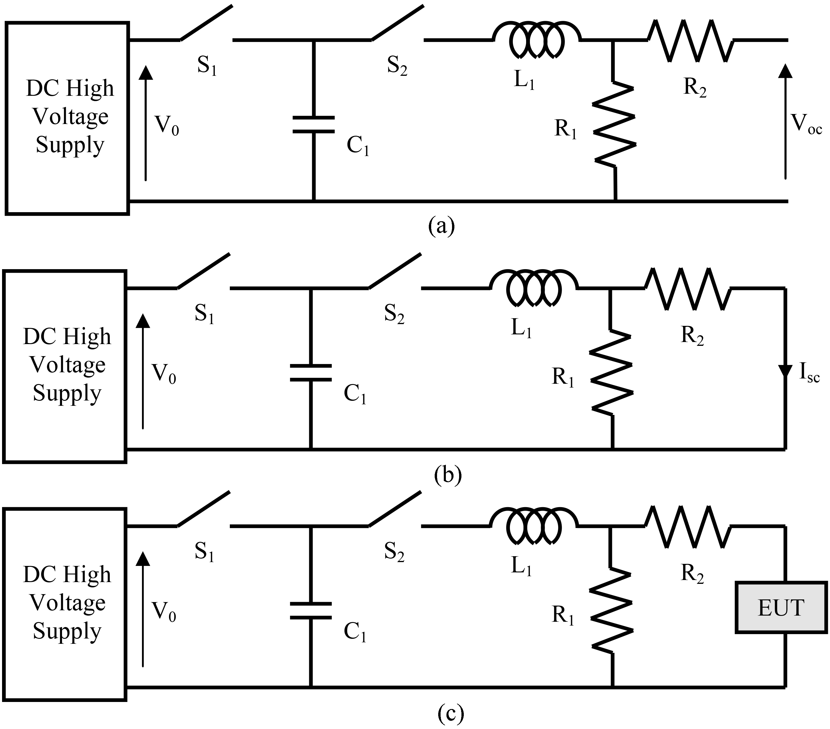
The parameters identification of this lightning generator is an inverse problem with multiple solutions and different accuracy levels respect to the standard requirements. Find the optimal solution is a very difficult task, in this section we propose a possible approach based on a genetic algorithm [7, 8, 9, 10, 11, 12]. The analytical expressions of Voc and Isc are indicated below
where
In order to reduce the computational time of the identification procedure we have chosen C1
where t
Results of the identification procedure
Main characteristics of the experimental set-up shown in Fig. 3
Experimental set-up of the lightning generator.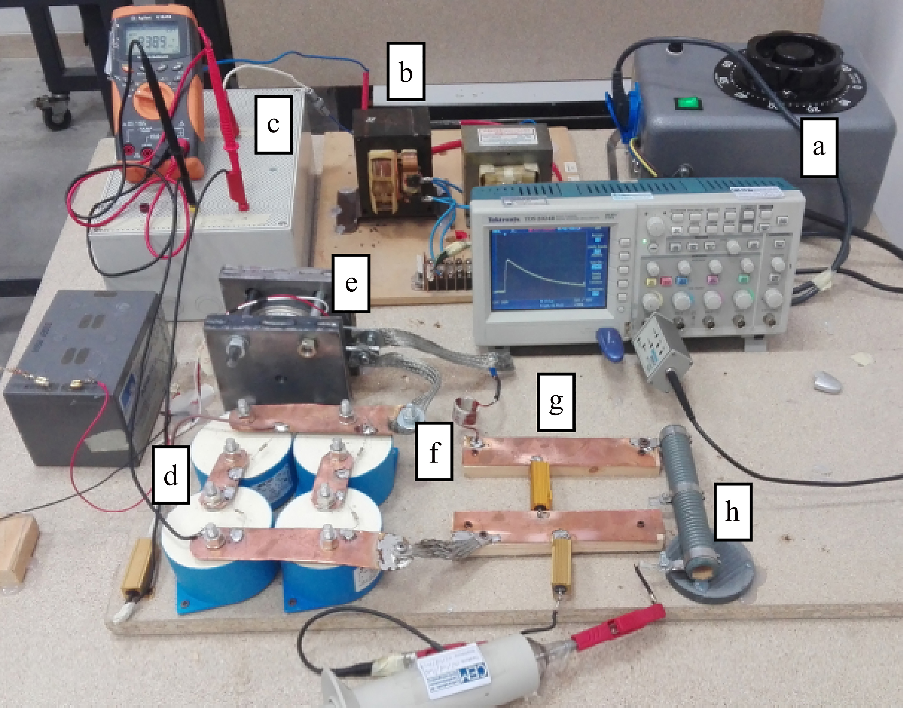
To prove the reliability of the genetic algorithm presented above for the parameters identification of a lightning generator, a dedicated experimental set-up is performed to generate the waveforms 4 and 1 from level 1 to 5. In Fig. 3 a picture of the experimental set-up is shown. The DC high voltage supply has three connected parts, (a) is an autotransformer to drive the voltage input of the transformer elevator (b), while the rectifier (c) converts the alternate current from the output of (b) in a direct current to charge the capacitor bank. The capacitor bank (d) is discharged trough the electronic switch (e) on the coupling net, made by an inductor (f), and the resistor (g) and (h). The main characteristics of these components are shown in Table 3. The voltage and current pulses are measured using the oscilloscope Tektronix TDS2024B, the high voltage probe Tektronix P6013 and the current probe Pearson Electronics 3525. The sample rate used has been up to 100 Ms/sec.
Comparison between computed data, experimental data and standard constraints in the open circuit calibration.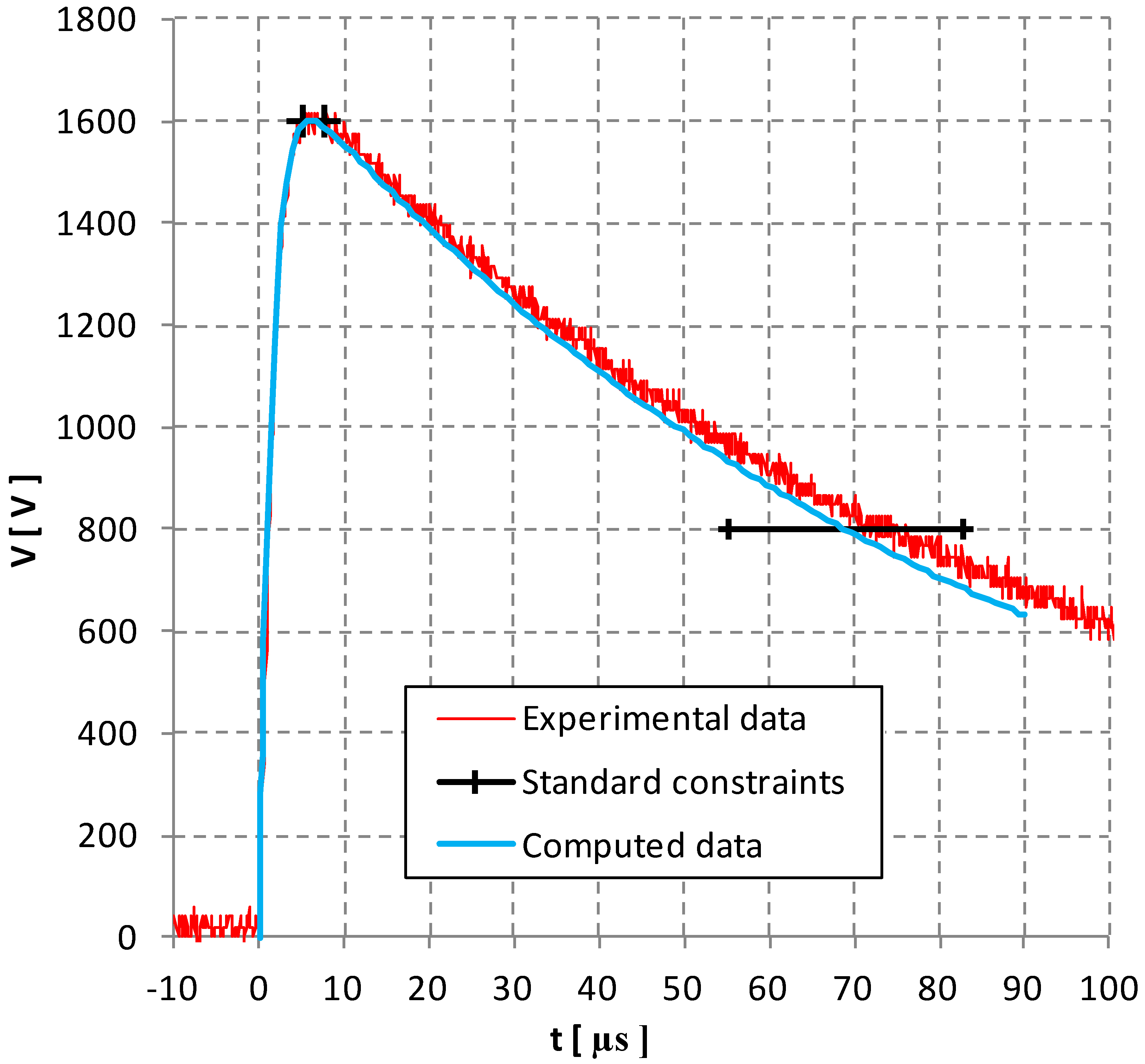
Comparison between computed data, experimental data and standard constraints in the open circuit calibration (rise time).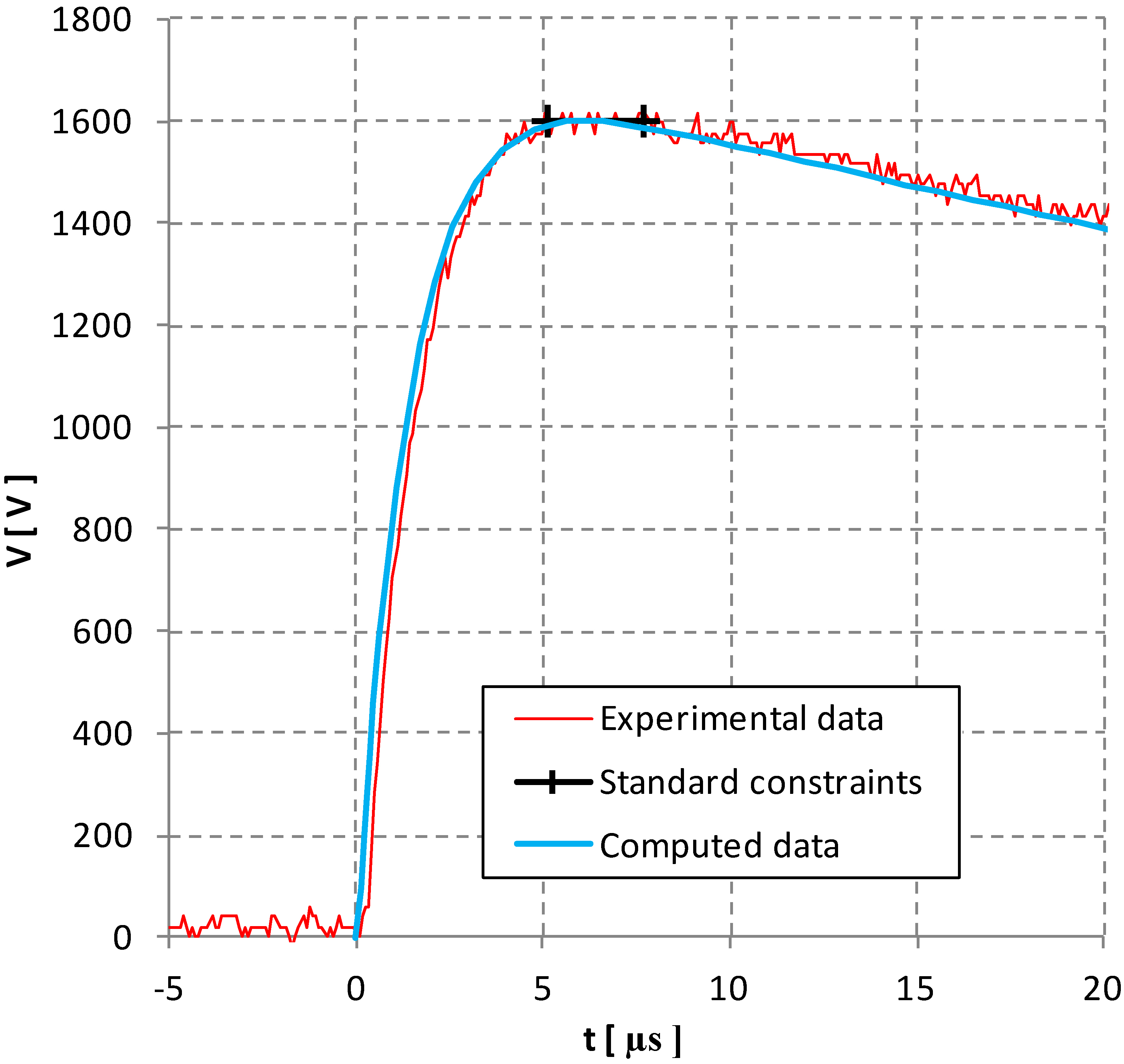
Comparison between computed data, experimental data and standard constraints in the short circuit calibration.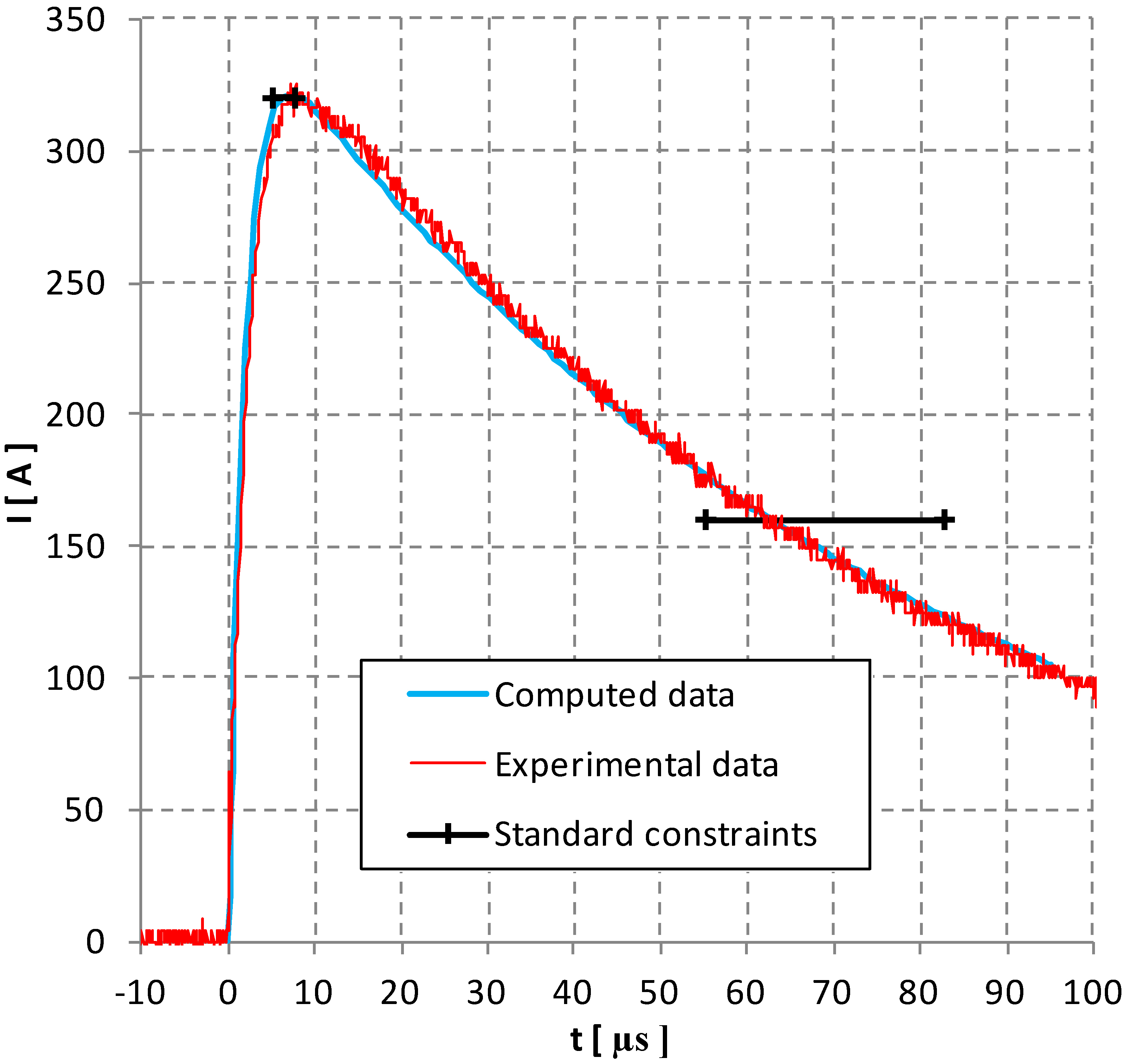
Comparison between computed data, experimental data and standard constraints in the short circuit calibration (rise time).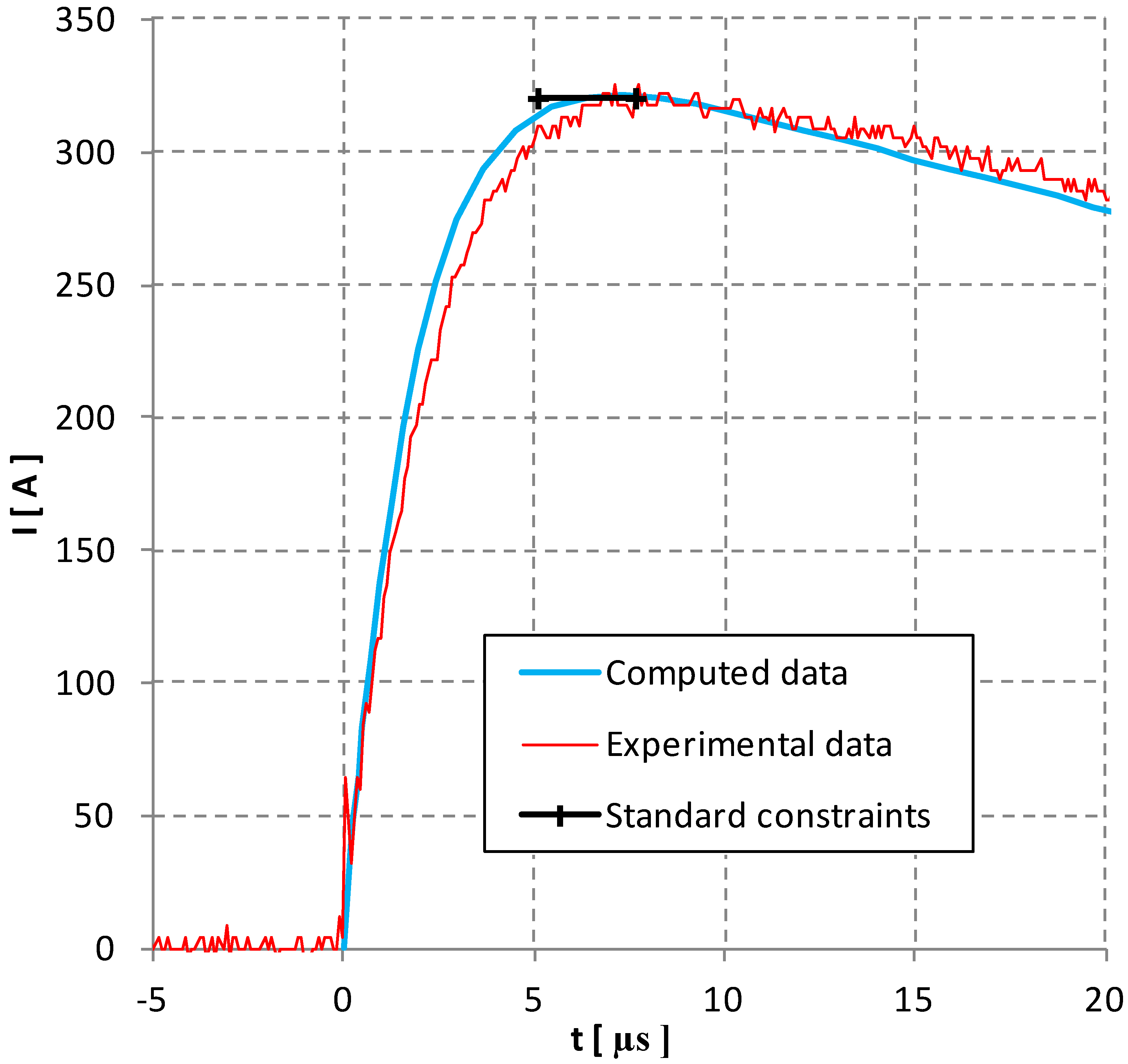
Open circuit waveforms for the levels 1 to 5.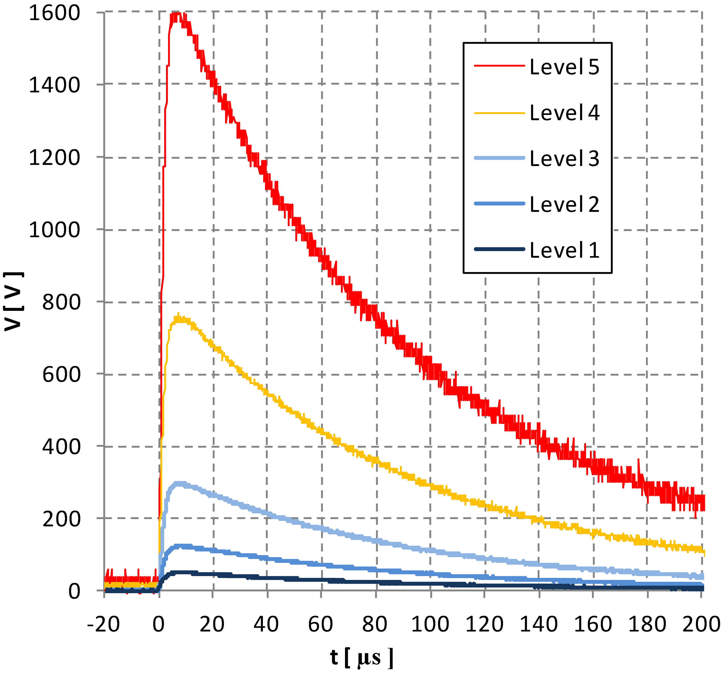
Short circuit waveforms for the levels 1 to 5.
In the Figs 4–7 a comparison between the calibration curves computed and measured with the standard constraints for the level 5 is reported. In particular in the Figs 4 and 6 are presented the overall waveforms respectively in the open circuit calibration (see Fig. 2a) and in the short circuit calibration (see Fig. 2b), while in the Figs 5 and 7 are highlighted the two corresponding rise times. The differences between the computed data, using the Eqs (1)–(3) with the identified values of the parameters, and the measured data using the experimental set-up presented in the previous section, are mainly due to the parasitic parameters of the circuit and the uncertainty of the component values, indicated in Table 3. In particular the parasitic inductance of the circuit is very critical: for this reason it is very important the use of tick and short interconnecting wires between the circuital components. Following this indication the accuracy of the lighting generator waveforms results more than satisfactory as indicated in the Figs 8 and 9 for the level 1 to 5. The highest test levels can generate damages for the components of the lightning generators because of the high values of voltages and currents. In the our experiments we have verified that the components used for the lightning generator listed in the Table 3, ensure robustness and repeatability of the waveforms up to level 5 without degradation of performances after many tests.
Conclusions
In this paper a possible approach to identify the generator parameters for the simulation of the indirect effects of lightning shots in avionic environment has been proposed. The accuracy and the reliability we get with this approach seems to be satisfactory compared to the standard requirements. In the paper only an example about the waveforms 1 and 4 of the standard [1] is presented, but the proposed approach can be extended to the other waveforms 2, 3, 5A and 5B, or to other similar test procedure where a pulse generator is involved, according to the different standards or custom requirements.
Footnotes
Acknowledgments
This work was partially supported by Fondazione CARIT Cassa di Risparmio di Terni e Narni (Italy).