
Abstract
This paper deals with computation on the ratio of rotor core width and insulator width to maximize the torque density and to minimize the torque ripple of axially multi-layer type synchronous reluctance motor (ALA-SynRM) for electric valve actuators. The thickness of the rotor core and flux barrier has the greatest effect on the flux path. Therefore, the optimum design on proportion of rotor shape for ALA-SynRM is proposed in this paper by coupled finite element method (FEM) and response surface method (RSM). Also, the characteristics dependence on the presence or absence of a rotor core rib, which causes magnetic saturation, was analyzed by calculating the inductance. Finally, the results of analysis are demonstrated through the simulation and by an experiment.
Keywords
Introduction
An actuator is an essential component in high demand caused by its application in a wide range of fields including industrial equipment, construction, robotics, shipbuilding, electrical vehicles, and aircrafts. The driving power source of actuators have been hydraulic and pneumatic in nature but, recently, actuators comprising electric drive systems have become popular because they simplified installation, and eased control and management. Induction motors are very often applied as actuator of driving source, but the demand for better actuators increases due to the low torque at low speed, efficiency problems, and reactivity/stability issues of induction motors [1, 2, 3]. Therefore, the feasibility of adopting an optimal design method and fabrication of an electric-actuator-driving synchronous reluctance motor (SynRM) was studied, as presented in this paper, with specific targets of high efficiency and high torque.
SynRMs according to laminated direction.
Two types of synchronous reluctance motors are shown in Fig. 1. Segment type synchronous reluctance motor has ribs in the flux barriers whereas axially laminated anisotropic (ALA) SynRM has good mechanical strength and higher saliency ratio [4, 5] due to its higher saliency ratio [6, 7]. The segment type SynRM has characteristics suitable for mass production and easy manufacturing processes. The ALA type SynRMs are capable of greater torque per unit weight because of the absence of rib in its mechanical structure. Such a structural characteristics of ALA type has good properties due to the large difference (
Therefore, in this paper, the ALA type SynRM is selected as an alternative of the electric actuator drive source and the methods of improving its torque density are studied. The torque and torque ripple characteristics, in consideration of the influence of the core magnetic saturation, are also analyzed by calculating the
Finally, the torque characteristics of the optimal design model are verified by comparing the finite element analysis simulation with the experimental results.
Range of the design
The stator of an axially laminated synchronous reluctance motor (ALA-SynRM) is similar to that of an induction motor, whereas the rotor is laminated in the axial direction of the shaft as shown in Fig. 1b. Alternate layers of the core sheets capable of punching and flux barrier (insulator) sheets are punched together in order to create an improved flux path between the cores. A non-magnetic material (spider) is used for the same purpose to assemble the structure between the shaft and the core. Magnetic flux flows well in a direction parallel to the laminated surface (
Mathematical modeling
As mentioned above, inductance values in the
where
The
where
Vector diagram of the current and voltage.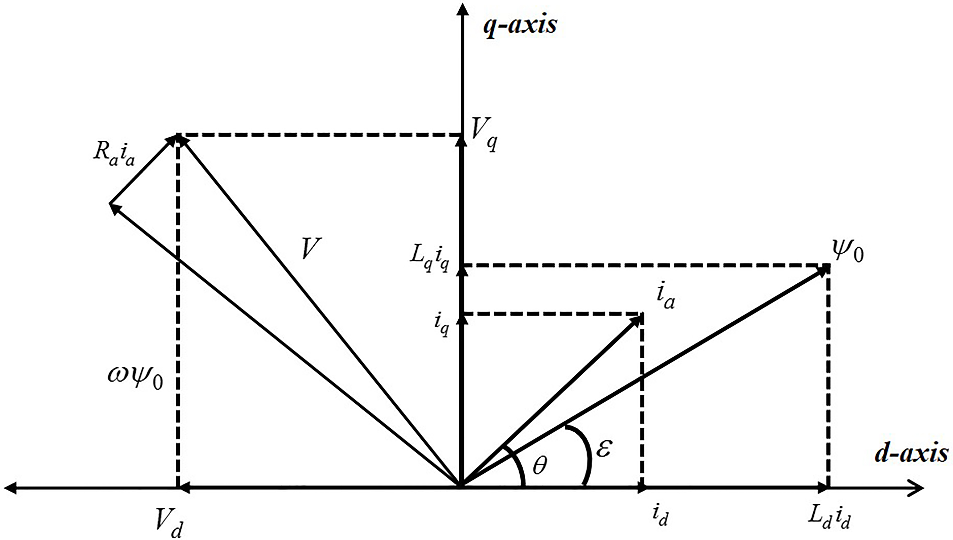
In SynRM, the power factor (PF) can be calculated by a function of the salient pole ratio [9].
Figure 3 shows the stator and the rotor of an ALA-SynRM and the design variables used for the optimal design. According to previous researches, main factors that affect the
Here,
Stator and rotor design variable range of the objective fuction
Design variables and variation direction of the initial model.
Therefore, the design parameter of the stator is the width of the open slot and design parameters of the rotor are the thickness of the iron core, the thickness of the insulating material and these position. Figure 4 shows the torque and torque ripple values for the design variable range considered. In particular, it can be seen that the change in the core thickness has a strong effect on the torque characteristics. In this paper, the
Main effect analysis by each design variables.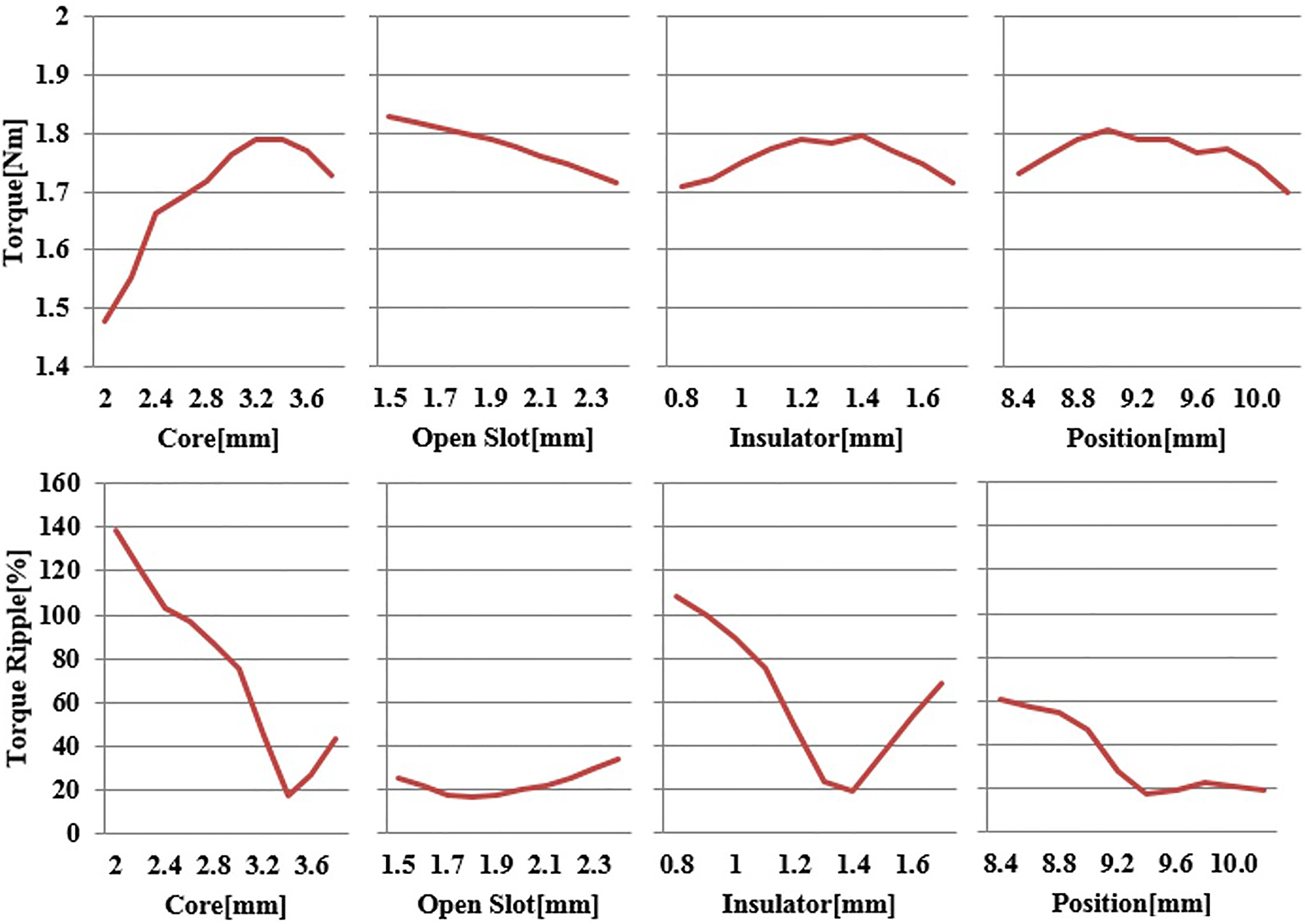
Response surface methodology (RSM) is a collection of statistical and mathematical techniques useful for developing, analysing, improving, and optimising the output or response of processes that are influenced by several independent input variables [11]. RSM was used by researchers developing the surface deposition model and surface roughness model [12]. There are many design of experiment (DOE) methods in the RSM, and this paper uses the Box-Behnken method. This method requires lesser number of experiments compared to other response surface methods for the optimization of same set of parameters and factors. If the range of the variable is determined, it may be advantageously used at the analysis time. Multi-characteristic optimal design cannot be performed in the DOE because it does not use S/N (signal/noise) ratio according to the smaller and larger the better characteristics.
Furthermore, there are many other parameters for optimizing the two objective functions in addition to the four parameters mentioned above [13, 14]. Therefore, we select the optimum model using an experimental design screening method to analyse the effects of these parameters on performance. Table 1 shows the range of design parameters for the objective function, and constraint conditions for the design of the stator and the rotor. The thickness of the iron core and the insulating sheet of an ALA-SynRM are considered. These thicknesses are limited by mechanical constraints such as the thickness of bolt head and the external diameter of the rotor. These parameters are designed considering the saturation of the iron core as well as the manufacturability. Table 2 shows the resulting values for torque and torque ripple due to changes in design parameters using the Box-Behnken method. Comparing the results, best parameters that result in maximum torque and a minimum torque ripple are selected for testing 7.
Experimental results of the objective function, the design variable using the Box-Behnken method
Experimental results of the objective function, the design variable using the Box-Behnken method
Results of the analysis model
The
Comparison of d-/q-axis inductance difference and ratio.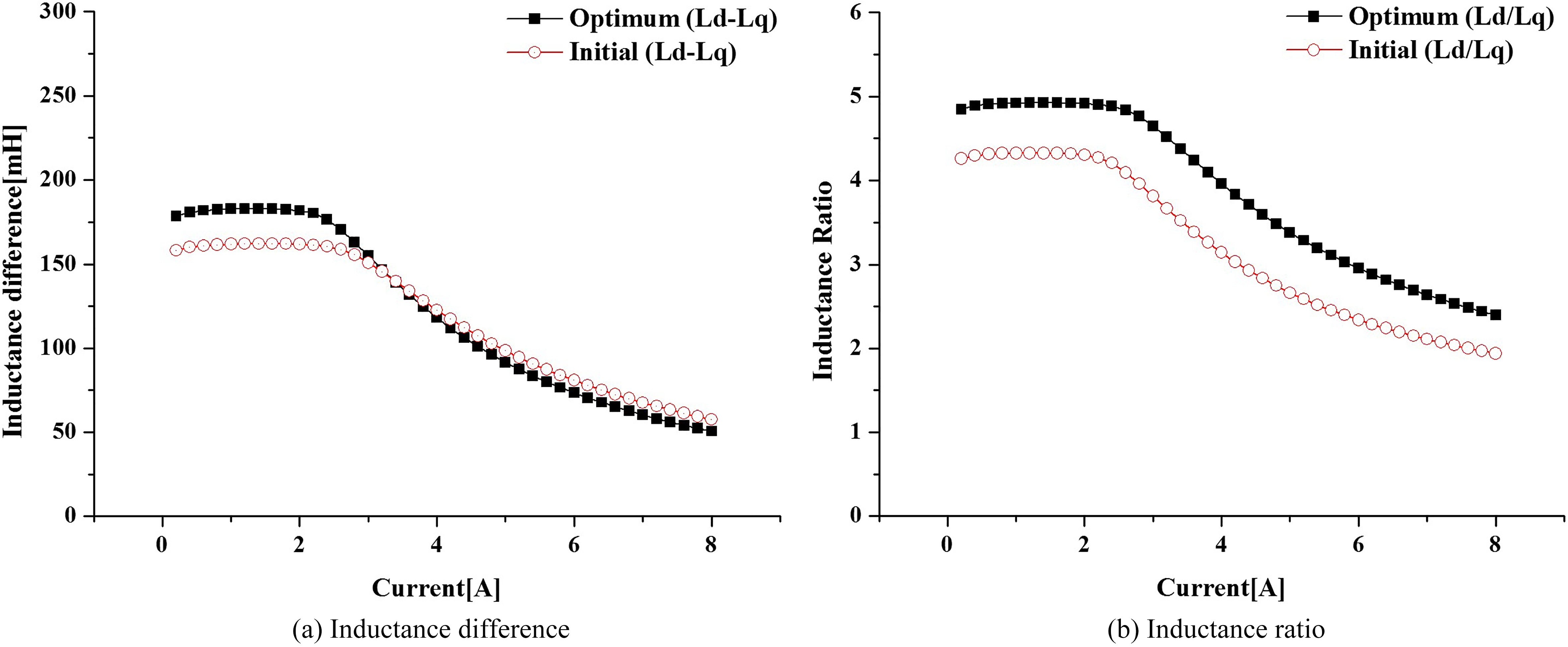
Figure 6 shows the variation curves of the inductance difference (
Comparison of the flux density at rated conditions (@ output torque: 1.8 [Nm], speed: 1800 [rpm]).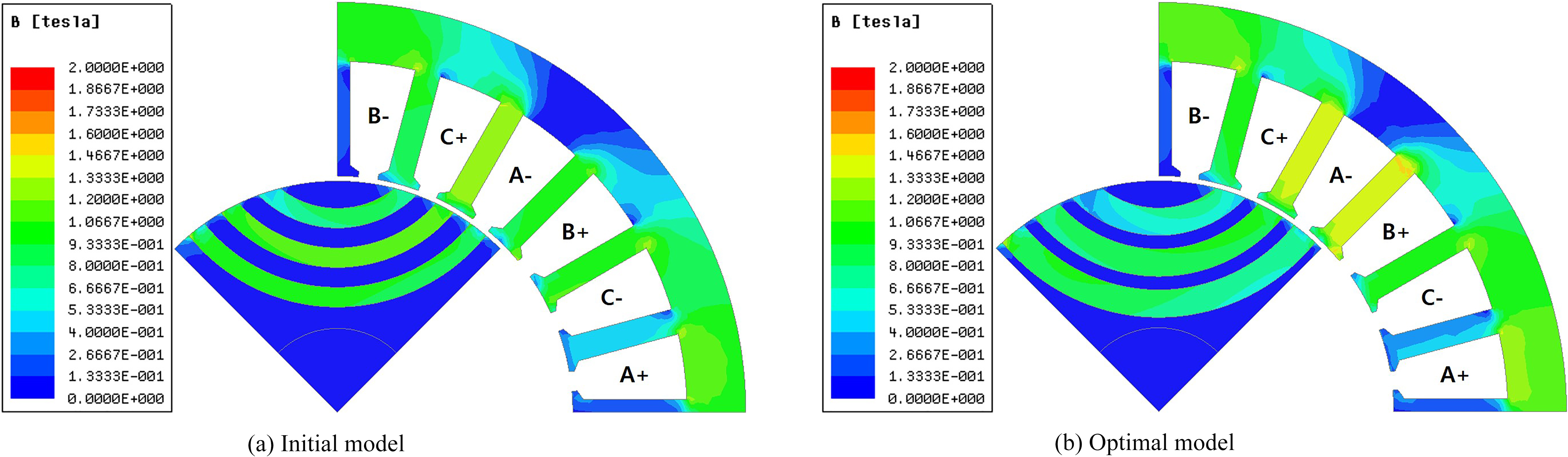
Torque and torque ripple according to the 
Photograph of experiment equipment and manufactured rotor shape.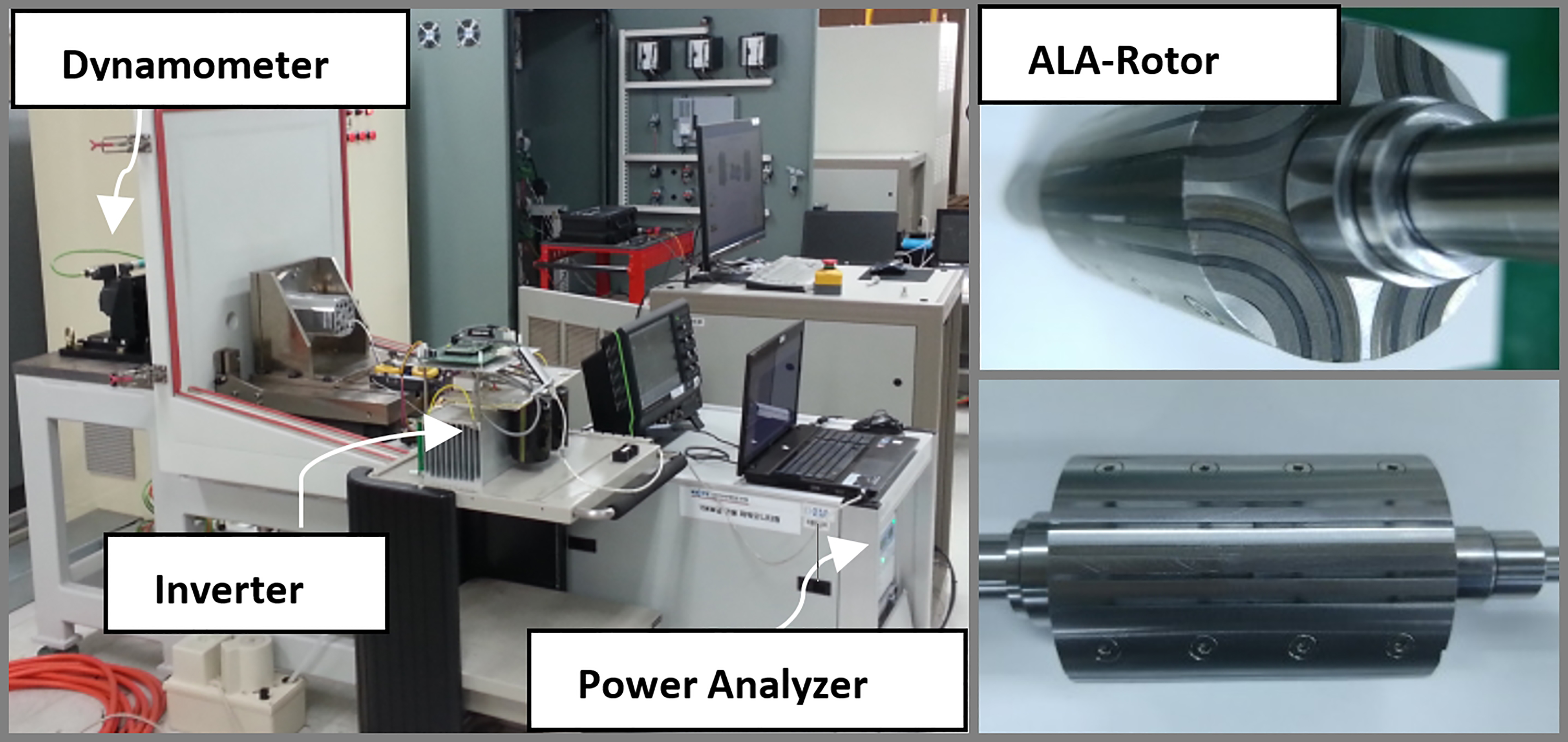
Comparison of the analysis result with FEM and experimentation.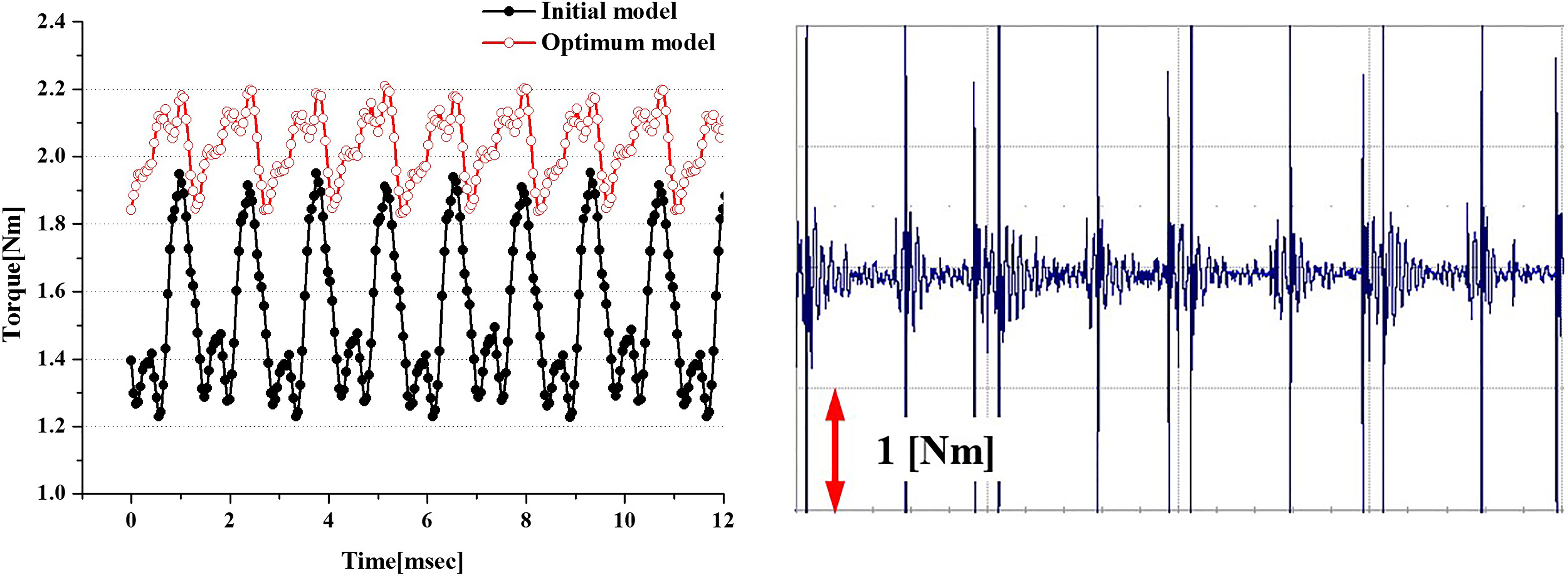
Figure 8 shows torque characteristics of according to the
One should notice that the design solutions should be related to the proportion of rotor structure, and this will be the important data in motor design of similar types.
To validate the performance of the proposed design model, an experiment was carried out using prototype motor in accordance with the targeted design. Experimental set up consisted of dynamometer, torque sensors, power quality analyzers, power supplies, and vector control inverters and the appearance of the rotor fully assembled, as shown in Fig. 9.
In order to obtain the higher characteristics owing to rotor structure, the characteristic of the optimum model with those of the initial model compared through Box-Behnken design. The torque characteristics of optimal model are represented as good results in Fig. 10. Finally, it can be demonstrated the results of analysis through the simulation and by an experiment. Figure 11 shows the comparison of the analysis results of the torque, back-EMF and current phase angle with that of experiment. Table 3 shows the comparison results of both model.
Conclusions
This paper deals with a design method for the optimal design of ALA-SynRM using response surface method coupled finite element method for use as a direct drive electric valve actuator.
Comparison of experimental results at rated condition
Comparison of the analysis result with FEM and experimentation.
And a method of design related to the torque density, the power factor, and torque ripple of ALA-SynRM according to the
In addition, this paper presents a design solution that is found through the comparison of inductance difference and torque ripple, according to the rotor shape proportion under the above condition. Through this study, it was determined that the motor torque is reduced due to the
Consequently, the appropriateness of design solution in a machine’s optimization method is verified through the simulation and by an experiment. Therefore, computation of
Footnotes
Acknowledgments
This work was supported by the Human Resource Training Program for Regional Innovation and Creativity through the Ministry of Education and National Research Foundation of Korea (NRF-2015H1C1A1033580).