
Abstract
Low forming accuracy is the main defects in electromagnetic forming process of sheet metal. One of the main reasons is that shapes of the coil and required workpiece are cylindrical and deep concave respectively. The distance between the coil and the side wall of deformed sheet metal is too far in forming process, which leads to a consequence that electromagnetic force in the side wall is not enough. To solve this problem, a solenoid field shaper was introduced to enhance the electromagnetic force at the side wall, and then improve forming accuracy of electromagnetic forming of sheet metal. To verify the effectiveness of the method, a series of simulations based on circuit-electromagnetic-structure were finished. The results showed that the maximum electromagnetic force with field shaper increased more than 10 times at the side wall. And the maximum deformation was 1.18 mm which can improve forming accuracy effectively. The presented method and results can be helpful in designing electromagnetic forming systems of sheet metal.
Introduction
Electromagnetic forming (EMF) is a high velocity forming technology, which can improve the formability of metal materials effectively. It is one of the most effective techniques to solve forming for low density alloys.
The plastic deformation is completed in microseconds in forming process, so forming process is difficult to control. The result is low forming accuracy in electromagnetic forming process of sheet metal. Up to now, most of the existing studies have focused on die forming to improve forming accuracy [1]. On the other hand, some researchers have applied multi-coils and multiple power supply to control the forming accuracy [2]. However, it is difficult to get the desired effect for some special workpieces. For example, an ellipsoidal metallic sheet derives from reference [3]. In its EMF processing with deep concave die, adopted axially movable electromagnetic forming system to get a high accuracy workpiece. However, once forming coil is wound, its basic structure has been fixed in EMF process. At the same time, forming coil will be subjected to a large inner stress according to Newton’s third law in forming process. So forming coil is designed as an axisymmetric structure. What’s more, the shape of the workpiece is constrained by die. Therefore, forming coil and the workpiece cannot be matched exactly. There will be the defect of insufficient deformation at the side wall.
Field shaper is a key tool in electromagnetic forming which can transfer and concentrate energy [4]. Yu et al. [5] carry out a numerical simulation of magnetic pressure acting on the tube during electromagnetic tube-compression forming with field shaper by means of the FEA software ANSYS. The results indicate that greater radial magnetic pressure can be achieved with field shaper than the case without it.
In this work, a solenoid field shaper was introduced in EMF system to solve the defects of insufficient deformation. In the following sections, the basic design principle of the system with field shaper was presented. And the effect of field shaper on electromagnetic force distribution and deformation were studied. Last, the deformation velocity was analyzed in forming process through simulation.
Methodology
Principle
Figure 1 shows the principle to improve forming accuracy by a solenoid field shaper. The system adopted axially moveable to reduce the axial distance between forming coil and the workpiece. Forming coil selection is similar to paper [2]. To make forming coil can be moved down into the cavity, the size of forming coil is designed relatively small. Figure 1b shows a fact that the deformation of the workpiece at the side wall is not enough. That means that there will be a deviation in the side wall (enlarged part).
The schematic diagram of the improved EMF system (a) before the first discharge; (b) the final shape in last discharge; (c) improved system with field shaper; (d) the final shape.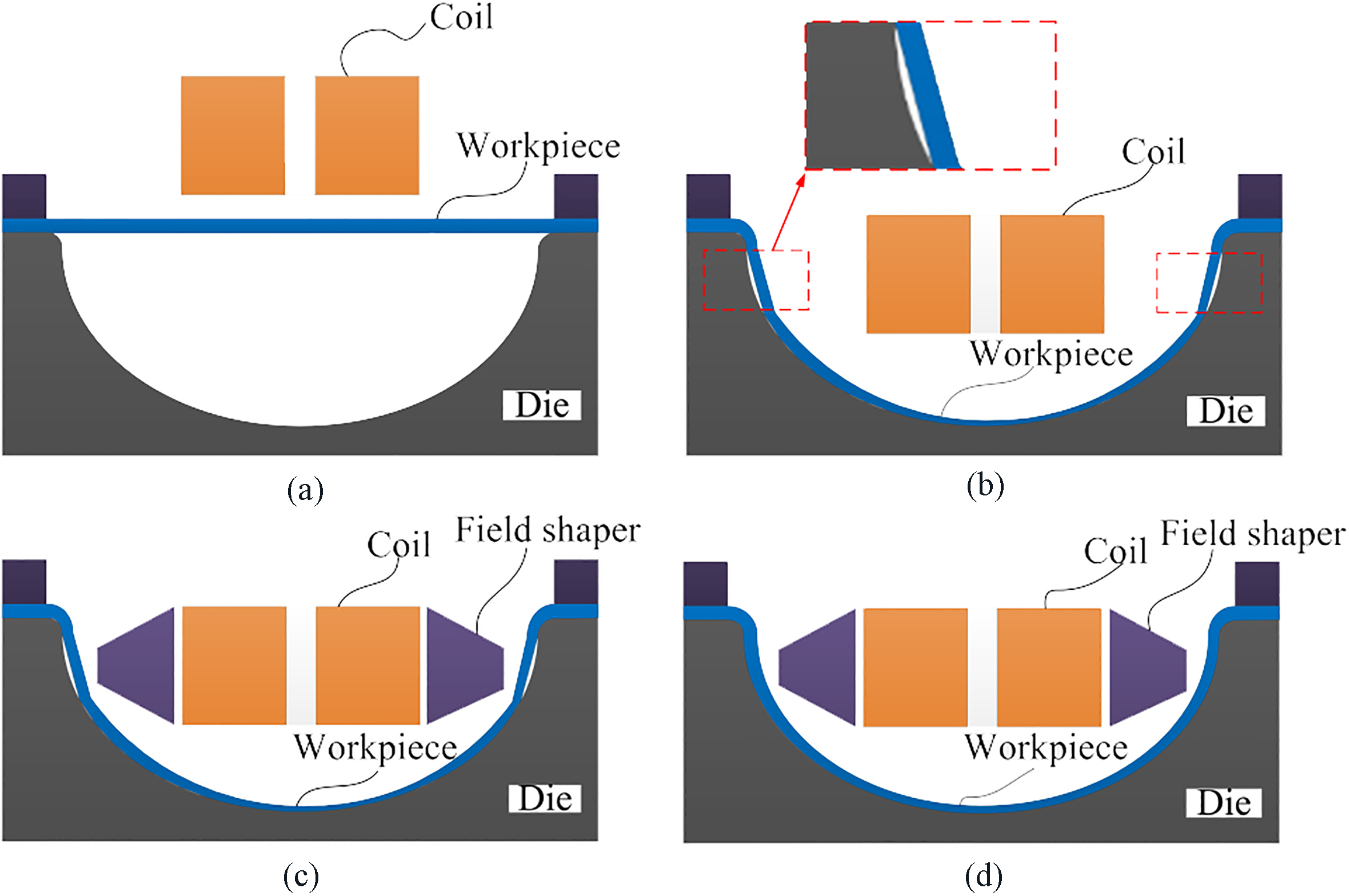
Current directions in forming coil, field shaper and the workpiece.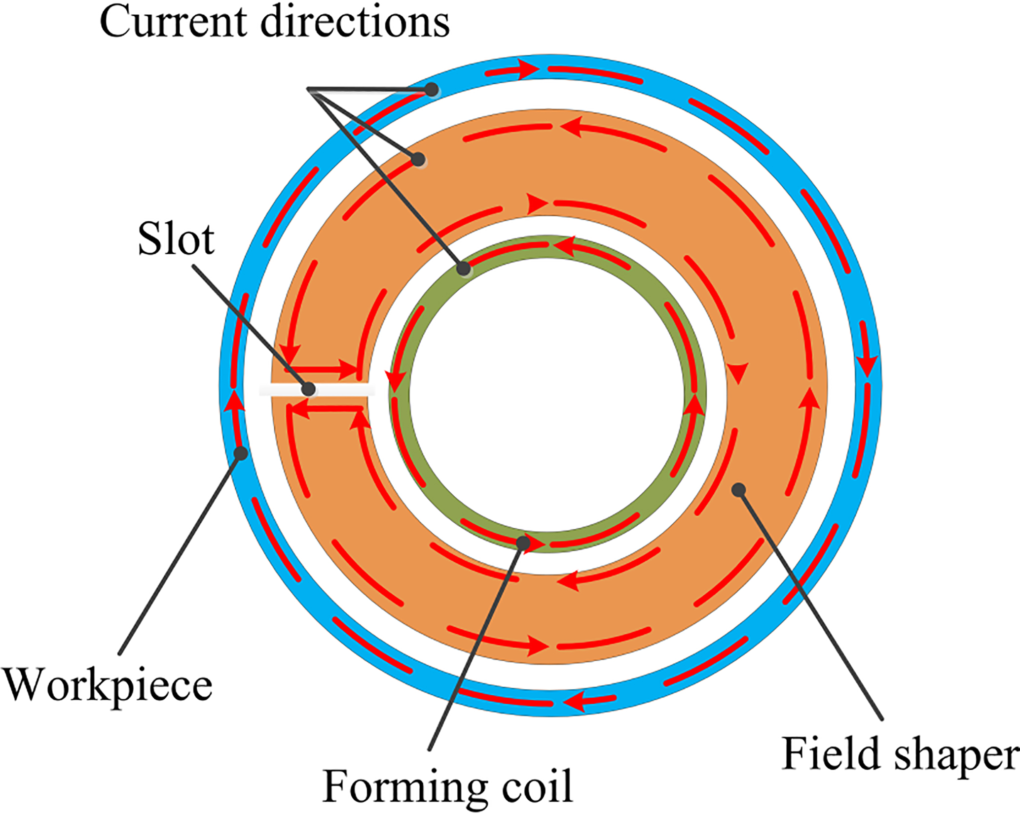
A field shaper is an axis-symmetric component made of an electrically high conductive material, which feature has an axial slot as shown in Fig. 2. In EMF process, the sudden discharge of the capacitor causes a damped sinusoidal current flowing through forming coil which induces a related eddy current. Due to the skin effect and Lenz’ law this induced eddy current flows to outer surface of the field shaper form the axial slot. Therefore the current direction is the same as in the forming coil. Therefore, the energy of the forming coil is transferred from forming coil to workpiece, equivalent to shorten the distance. The skin depth is determined by
Where
Based on this, field shaper was applied in this system to improve the deformation in the last step as shown in Fig. 1c. Figure 1d shows the expected effect of the workpiece finally.
Electromagnetic force can be decomposed into axial and radial component in the analysis of an electromagnetic forming process [6], which is called as radial Lorentz force (
Where
The main purpose of this paper is to sizing the sheet metal, so only need to analysis the formed workpiece which has defects. There are several coupling models in simulation in the EMF process, including loose coupling, sequential coupling [7] and full coupling. The 2D axisymmetric full coupling model we used in this paper derives from reference [8], which described the construction details of this model and proved its effectiveness theoretically and experimentally. What’s more, it has higher accuracy than the existing loose coupling and sequential coupling models.
Figure 3 shows the geometric model of the process. It is obviously that forming coil consists of 48 turns and each turn’s sectional area is 2 mm
In structural field analysis, the sheet metal material is annealed 5052 aluminum alloy which depth is 2 mm. Its elastic modulus is 69 GPa, Poisson ratio is 0.3 and Yield strength is 105.6 MPa [9]. Meanwhile, it considers the effect of strain rate on the forming process, Cowper – Symonds constitutive model was adopted [10]. The formula is as follows
Where
The discharge current in simulation is calculated by ordinary differential equations (ODEs) which based on Cao et al.’s paper, the ODEs contain crowbar circuit [11]. And detail parameters have been shown in Table 1.
Main parameters
Geometric model of the process.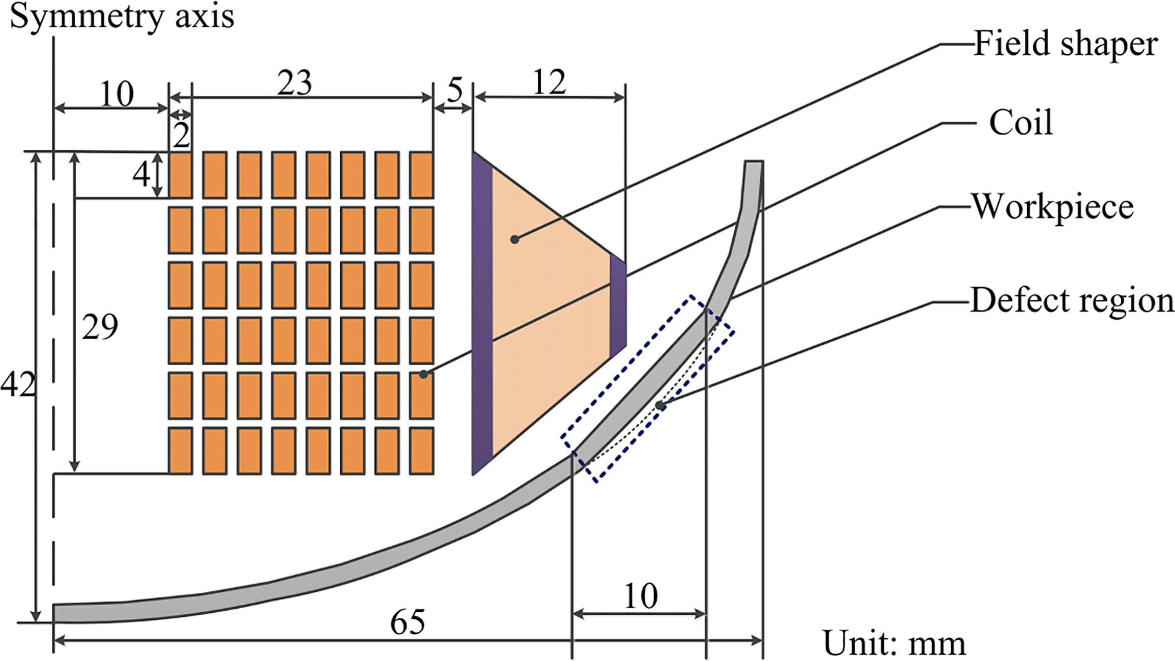
To verify the effectiveness of this method, two sets of the FEA models had been established. The only difference is whether there is a field shaper, and the other’s parameters remain unchanged.
The waveform of discharge current.
Figure 4 shows the waveform of discharge current in the same energy (2.88 kJ). According to waveform and Eq. (1), the skin depth is about 1.4 mm. From the chart, it can be seen clearly that discharge current amplitude increases slightly relative to the system without field shaper, and the time to reach the peak advanced 14
To verify the proposed method, the calculation results of the workpiece deformation have been compared, as shown in Fig. 5. It can be seen intuitively that the radial displacement of the workpiece has been improved significantly in defects region. Simultaneously, the workpiece in Fig. 5b looks smoother than Fig. 5a. So the system with field shaper can improve the deformation effectively in the side wall.
The simulation results of the radial displacement (a) without field shaper; (b) with field shaper.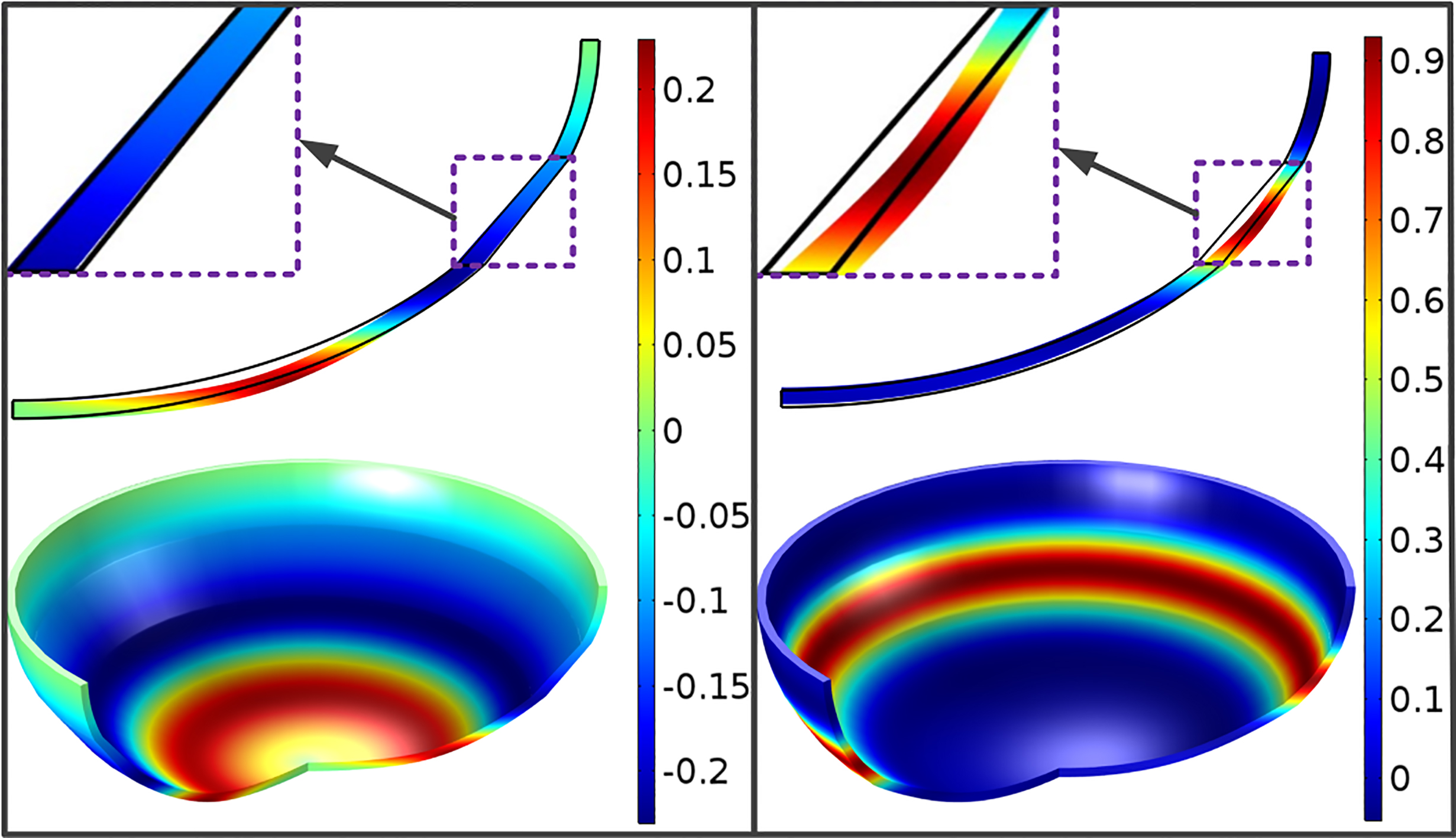
Calculated radial displacements of the sheet.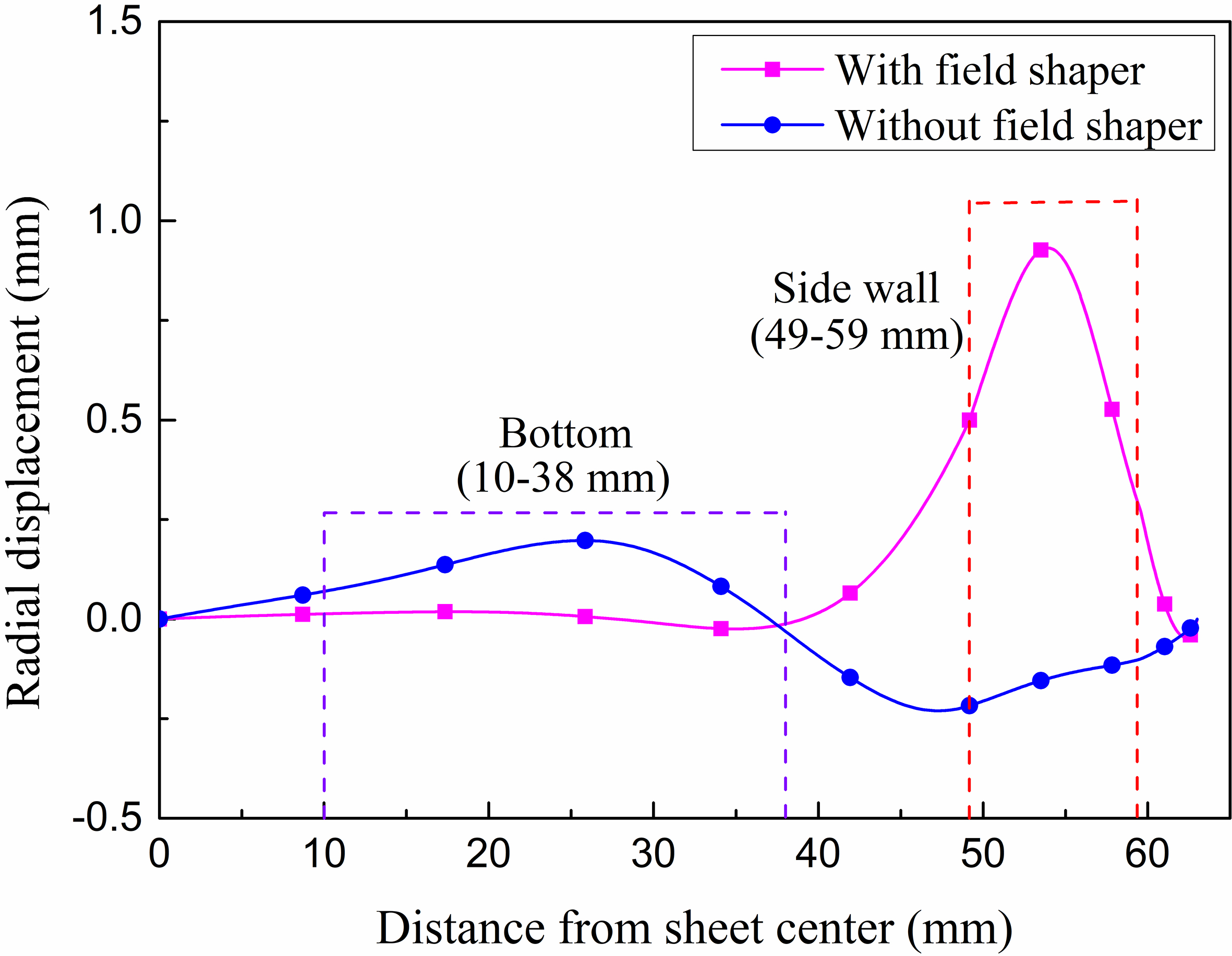
Calculated axial displacements of the sheet.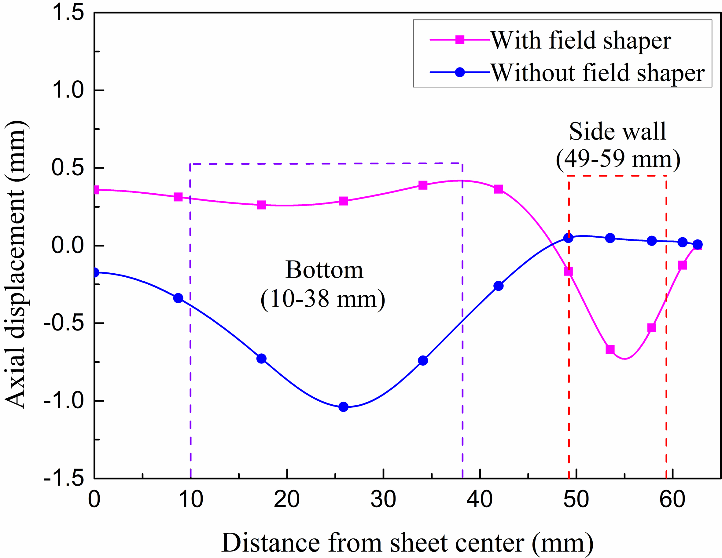
The radial displacements and axial displacement of sheet under different systems are calculated as shown in Figs 6 and 7, respectively. It can be seen that the displacement in the side wall have been improved clearly relative to the system without field shaper. The radial and axial maximum values are 0.932 mm and 0.73 mm respectively. However, the displacement in the bottom decreased, and uplifted slightly. Because the workpiece was free formed, the deformation of the side wall will stretch the bottom.
In the EMF process, the workpiece deformation relies on the inductive electromagnetic force between the coil and the metal sheet. So an accurate calculation of the electromagnetic force is essential to analyze the EMF process and predict the workpiece deflection.
According to Eqs (2) and (3), Electromagnetic force is decomposed into axial and radial. In this paper, based on results in Figs 8 and 9, a marked change exists in radial and axial Lorentz force density in the side wall. Radial Lorentz force density and axial Lorentz force density have been improved more than 10 times. This means that Lorentz force can be strengthened in the side wall by field shaper. But axial Lorentz force decreases with field shaper in the bottom. This mainly affected by field shaper, the main reason is that magnetic field has changed when adding field shaper in circumferential This result also corresponds to Fig. 7, the deformation of the bottom was affected by the side wall.
Distribution of maximum radial Lorentz force density along sheet.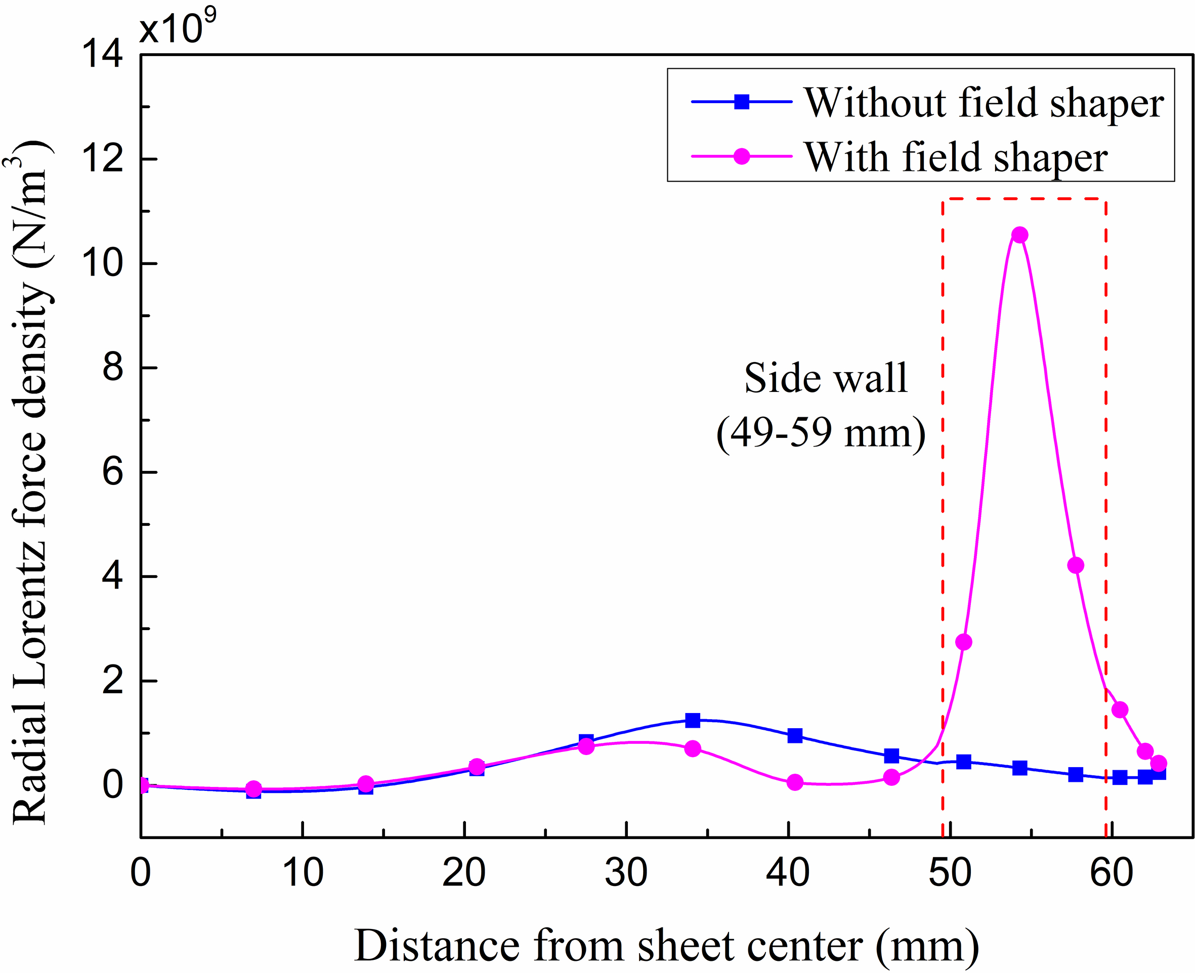
Distribution of maximum axial Lorentz force density along sheet.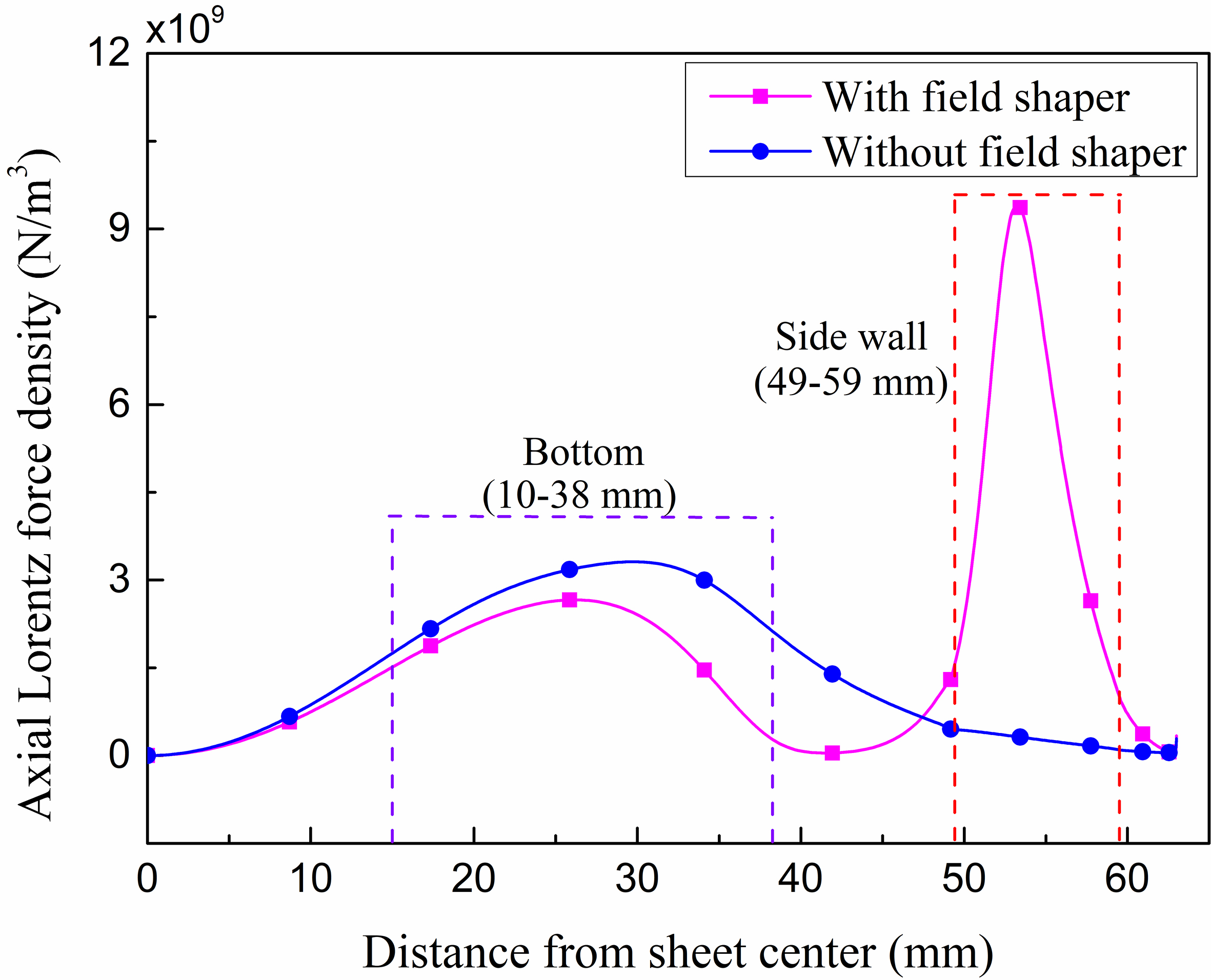
Deformation velocity at the center of the inner defects region.
During the electromagnetic forming process, the workpiece will move with a high deformation velocity, which can be calculated as the derivative of the deformation displacement. In this paper, Fig. 10 shows the velocity at the center of the inner defects region. It can be seen that the deformation velocity is low relatively, and the maximum radial and axial velocity is 16.9 m/s and 13.3 m/s respectively. This is due to the fact that this work is aimed at sizing rather than the large deformation. So the energy loaded in EMF system is 2.88 kJ, relatively small.
Displacement of the sheet with and without velocity term.
Figure 11 shows a comparison of the displacement along sheet with and without considering the velocity effect. The final calculated radial displacement with and without velocity term are 1.377 mm and 0.932 mm. And axial displacement with and without velocity term are 0.93 mm and 1.047 mm. Therefore, velocity term has great influence on deformation. So the velocity must be considered in EMF process to improve the forming accuracy.
Electromagnetic force descends quickly with the increasing distance between forming coil and deformed workpiece in EMF process, which leads to a low forming accuracy at side wall of the workpiece. To overcome this defect, a field shaper was introduced to enhance the electromagnetic force at side wall of the workpiece. In this work, a series of simulations have been run to verify the effectiveness of this new method. Our results show that the electromagnetic force increased more than 10 times. And the deformation have been improved at the side wall, the maximum deformation is 1.18 mm. It’s suggested that field shaper can improve forming accuracy effectively in this system. What’s more, all these simulation results can be very helpful in designing electromagnetic forming systems of the sheet metal.
Footnotes
Acknowledgments
This work was funded by Research Foundation of Education Bureau of Hubei Province, China (Z2017030, Q20171210) and State Key Laboratory of Advanced Electromagnetic Engineering and Technology (Huazhong University of Science and Technology).