
Abstract
This paper studies thermal modeling and parameter determination for a permanent magnet generator with built-in hydrostatic drive, which has some special thermal characteristics including being cooled by circulating hydraulic oil and being filled with leaked hydraulic oil. To predict its temperature, a thermal model is developed by analyzing thermal sources and heat transfer paths and reasonably simplified based on empirical analysis. Then system identification is implemented to determine the model’s main parameters such as thermal resistances and thermal capacitances. The variations of heat transfer coefficients due to rotational speed and oil viscosity are taken into consideration through theoretical correction. Finally, comparisons between calculated results and experimental results under different load conditions are presented to verify the effectiveness of the thermal model. The effects of ambient temperature and input oil temperature on the temperature rise are also investigated based on the model. This study can also provide reference to the temperature estimation of those similar machines filled with liquid.
Introduction
A hydrostatic-driven permanent magnet generator is an energy conversion device which converts hydrostatic energy to electrical form directly in hydrostatic transmission system. Its main applications can be categorized into renewable energy exploitation [1–4] and energy recovery [5–7]. In recent years, there has been an increasing requirement of this machine with the aggravation of energy crisis.
Figure 1 shows the schematic diagram of a compact permanent magnet generator with build-in hydrostatic drive [8,9]. Different from conventional generators, the rotor of this machine is composed of permanent magnets and hydrostatic driving mechanism. When pressurized hydraulic oil is supplied through the input port and discharged through the output port, the rotor will be driven to rotate and electromotive forces will be induced in the stator windings. Since there exists inevitable leakage from the pressurized chamber, leaked hydraulic oil will fill the cage interior and get discharged through the leakage port. The shaft end is just used for speed detection rather than power transmission.
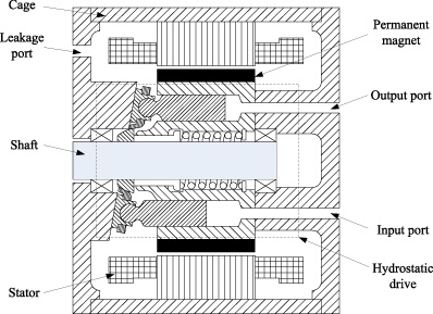
Schematic diagram of the permanent magnet generator with built-in hydrostatic drive.
Thermal performance has strong effect on the reliability and lifetime of electrical machines. There are a number of literatures about how to estimate the temperature in electrical machines and a detailed review has been presented in [10]. It is reported that analytical lumped-circuit and numerical methods are two basic types of thermal analysis. The analytical approach has been widely applied due to the advantages of clear physical meaning and relatively efficient computation [11–13].
In the analytical thermal model, the machine is divided geometrically into a series of lumped components each of which have thermal capacitance, heat generation and interconnections to neighboring components through a linear mesh of thermal resistances [14,15]. Then the component temperature can be obtained by calculating the thermal circuit that simulates the heat transfer paths. Despite significant improvement in comparison with numerical methods, the implementation of a full-order thermal circuit is still a formidable challenge, especially when real-time response is required [16]. Therefore, simplification techniques using thermal behavior analysis and mathematic tool are proposed to realize order reduction [17–19]. It is also noticed that parameter determination is another important aspect in thermal modeling [20]. Generally, theoretical calculation is not enough to estimate parameters accurately, and empirical and numerical methods are often employed [21].
Although the methodology of the lumped-circuit thermal analysis has been well developed for electrical machines, it cannot be directly employed in the thermal analysis of the studied machine due to some special thermal characteristics including being cooled by circulating hydraulic oil and being filled with leaked hydraulic oil. Moreover, it is difficult to determine parameters when rotational speed and oil viscosity are not constant.
In this paper, a simplified thermal model of the studied machine is proposed by analyzing thermal sources and heat transfer paths. Then system identification with theoretical correction is implemented to determine the model’s main parameters. Finally, the model’s effectiveness is verified by comparisons between calculated results and experimental results under different load conditions. The developed model can also provide reference to the temperature estimation of those similar machines filled with liquid.
As shown in Fig. 1, the thermal sources of the permanent magnet generator with build-in hydrostatic drive are summarized as follows: copper loss in the stator windings, iron loss in the stator iron core, eddy-current loss in the rotor, mechanical loss and leakage loss in the hydrostatic drive. The generated heat can transferred out through the cage surface, the circulating hydraulic oil and the leaked hydraulic oil. It is also necessary to pay attention to the hydraulic oil flows which affect heat transfer. The two main types are the channel flow of the circulating hydraulic oil in the rotor and the shear flow of the inner hydraulic oil in the airgap.
According to the geometry and thermal characteristics of the studied machine a lump-circuit thermal model is proposed as shown in Fig. 2. It can be seen that the machine is divided into five components which are the rotor, the hydraulic oil in the airgap, the stator windings, the stator iron core and the cage, which are represented by the nodes numbered from 1 to 5, respectively.
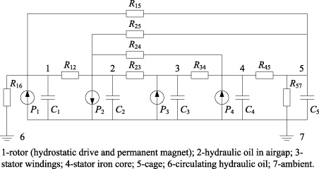
A lumped-circuit thermal model of the studied machine.
The symbols in Fig. 2 are described as follows. C i denotes the thermal capacitance of the ith node. P 1 denotes the total losses in the rotor which is the sum of eddy-current loss, mechanical loss and leakage loss. P 2 denotes the heat transferred out by leaked hydraulic oil. P 3 and P 4 denote copper loss and iron loss in the stator. R ij denotes the thermal resistance between the ith node and the jth node. It should be mentioned that R 16 is the convection thermal resistance between the rotor and the circulating hydraulic oil, and R 57 is the convectional thermal resistance between the cage and the ambient.
Although the heat transfer paths involve every parameter aforementioned, the temperature computation in practice is mainly affected by a reduced number of thermal parameters. To make the model efficient and robust, some simplifications are carried out reasonably based on empirical analysis. Firstly, the axial heat transfer path between the rotor and the cage is ignored, because axial thermal resistance is usually much larger than radial thermal resistance. Secondly, preliminary tests show that R 25 is relatively large in comparison with the resistance in its parallel path and then can also be ignored. Thirdly, the clearance in stator slots is filled with hydraulic oil, which results in the resistance between the windings and the iron core of the stator is too small to consider, therefore, the windings and the iron core can be treated as a single node. Fourthly, the nodes of the rotor and the hydraulic oil in airgap are combined as the node of an equivalent rotor by using corresponding thermal capacitance and thermal source, for this simplification can eliminate the difficulty of identifying R 12 when temperature sensors are absence in the two nodes.
Figure 3 shows the simplified lumped-circuit thermal model where the interests are focused on the equivalent rotor, the stator and the cage. To calculate the temperatures in the nodes, it is necessary to determine the quantities of the symbols in advance, including the thermal sources (P r , P s ), thermal resistances (R ro , R rs , R sc , R ca ), and thermal capacitances (C r , C s , C c ).
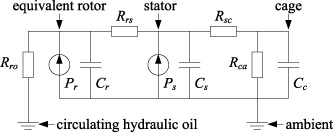
The simplified lumped-circuit thermal model of the studied machine.
Prototype
A prototype of the compact permanent magnet generator with build-in hydrostatic drive is introduced as a case study. The basic parameters of the prototype are given in Table 1.
Basic parameters of the prototype
Basic parameters of the prototype
Figure 4 shows the main temperature measuring points of the prototype where PT100 sensors are applied. It can be observed that plug-type sensors are adopted to detect the temperature of liquids including the hydraulic oil in the input, output and leakage ports, and paste-type sensors are adopted to detect the temperature of solids including the cage and the stator.
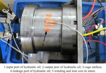
Temperature measuring points of the prototype.
The input hydrostatic power and the generated electrical power are given as
The leakage loss is given as
As the mechanical loss is difficult to obtained directly, an indirect approach is used to separate the mechanical loss from the total losses with the following expression
Thus, the thermal source in the stator, which is equal to the sum of the copper loss and the iron loss, can be obtained by
The thermal source in the equivalent rotor can be obtained by
The working flow rate is proportional to the rotational speed and can be expressed as
According to preliminary tests, the leakage flow rate is proportional to the input pressure and can be expressed as
Steady experimental results are used to estimate the thermal resistances. As shown in Fig. 3, R sc and R ca can be considered as constant, but R ro and R rs are too much dependent on the rotational speed and the oil viscosity. For example, when the rotational speed is zero, R ro is almost equal to zero, for there is no circulating hydraulic oil used for heat transfer.
With regard to R
sc
and R
ca
, dc test is used to determine their quantities. In the dc test, the machine is kept static and the windings are supplied with dc power. Then by measuring the temperatures of the stator, the cage and the ambient, R
sc
and R
ca
can be determined by the following expressions
With regard to R
ro
and R
rs
, two steps are implemented so as to take their nonconstant property into account. Firstly, the quantities of R
ro
and R
rs
used as reference are calculated according to the following equation set under both of loaded and no-load conditions when the rotational speed is about 1500 rpm and the circulating oil temperature is about 20 degrees
Table 2 summarizes the identified quantities of the thermal resistances.
Identified quantities of the thermal resistances
The second step is to make theoretical correction based on R
ro, ref
and R
rs, ref
calculated above. Some physical quantities involved in convection heat transfer are written as
Considering round flow channel and laminar flow state, the following expression is available for the flow of the circulating hydraulic oil in the rotor [23]
The shear flow of hydraulic oil in the airgap is more complex. Taylor number Ta is usually calculated by using the following expression to judge the flow state
where Nu specifically denotes the quantity calculated by using (23).
The lumped-circuit thermal model can be expressed by the following linear differential equations
Since manual calculation is complicated for the three-order parameter-varying system, MATLAB’s system identification toolbox is employed in this study and the specific operation method can be found in [24].
The reference data of system identification utilizes the measured temperatures of the stator and the cage under loaded condition at the rated rotational speed and Table 3 gives the best fitted results of which the fit precision is about 92%. Figure 5 and Fig. 6 show the comparisons between the measured temperature and the calculated temperature of the stator and the cage, respectively.
Identified quantities of the thermal capacitances

Stator temperature under loaded condition at rated rotational speed.
Cage temperature under loaded condition at rated rotational speed.

Schematic of experimental setup for the prototype.
In this section, more experimental results are obtained to verify the developed thermal model and determined parameters. Loss tests have been implemented at some typical operating points of the prototype, where the generated electrical energy is supplied to a resistive electrical load or without load. Figure 7 presents the schematic of the experimental setup which mainly consists of a prototype, an adjustable hydrostatic power source, a resistive electrical load, and various sensors. The hydrostatic power source can provide a variable flow rate by controlling the displacement of the hydrostatic pump. The relief valve serves as a safety valve and the filter is used to ensure the cleanliness of the hydraulic oil. A pressure sensor and a flow meter are employed to measure the pressure and the flow rate of the hydraulic oil flowing into the permanent magnet generator with built-in hydrostatic drive. A resolver and a signal modulator card are used to detect the rotational speed. Current and voltage sensors are employed to measure the generated voltages and currents. In addition, a computer and data I/O cards are employed to acquire data and provide control signals to the variable-displacement pump. According to (1)--(9), the losses and the thermal sources can be obtained by combining measured data and the prototype parameters.
Table 4 presents the measured results and the loss distributions. It can be observed that the copper loss and the mechanical loss form the majority of the total loss. The measured leakage flow rate is less than 0.5% of the input flow rate, thus the leakage loss is almost ignorable.
Measured results and loss distribution at some typical operating points
Measured results and loss distribution at some typical operating points
Stator temperature under no-load condition at rated rotational speed.
Since the loaded results have been verified in the previous section, the model performance under no-load condition is also concerned. Figure 8 and Fig. 9 show the stator temperature and the cage temperature under no-load condition at the rated rotational speed. It can be observed that the measured results and the calculated results are in good agreement.
Cage temperature under no-load condition at rated rotational speed.
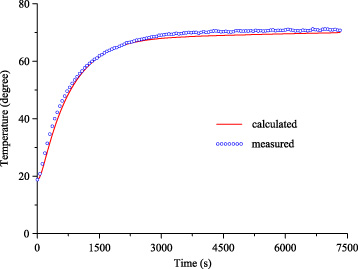
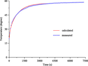
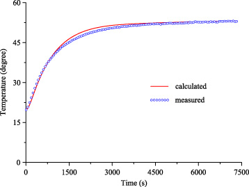
To further examine the model’s effectiveness, an experiment under variable-load condition is designed and carried out. In the variable-load condition, the rotational speed of the permanent magnet generator varies in a large range as shown in Fig. 10 and the output electricity is supplied to a three-phase resistive load of 15 Ω.
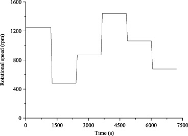
Rotational speed curve under the variable-load condition.
Figure 11 and Fig. 12 show the corresponding temperatures of the stator and the cage under the variable-load condition, respectively. It can be seen that there exist certain errors between the calculated results and the measured results because of the model simplification and the error in system identification. However, in general, the calculated curves can track the measured curves with an acceptable precision.
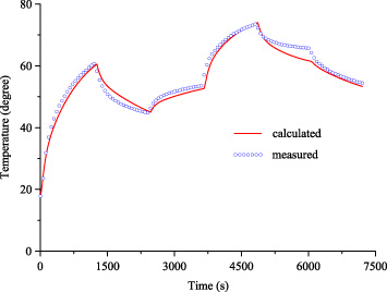
Stator temperature under variable-load condition.
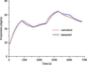
Cage temperature under variable-load condition.
Based on the thermal model, the effects of the input oil temperature and the ambient temperature on the prototype temperature rise are investigated. Figure 13 and Fig. 14 presents the temperature rise in the stator, the cage and the rotor varying with input oil temperature and ambient temperature respectively. It can be observed that the input oil has more significant influence on the temperature rise than the ambient temperature in general. In addition, the temperature rise in the rotor is sensitive to the input oil temperature while the temperature rise in the cage is sensitive to the ambient temperature.

Effect of input oil temperature on prototype temperature rise.
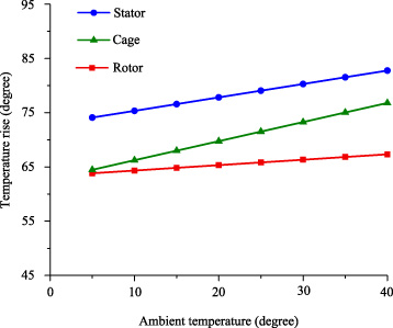
Effect of ambient temperature on prototype temperature rise.
This paper concentrates on the thermal analysis of a permanent magnet generator with built-in hydrostatic drive. With sufficient understanding about the machine’s thermal behavior, a simplified lumped circuit and a feasible procedure of parameter determination are proposed. Moreover, theoretical correction is especially introduced to take the effects of rotational speed and oil viscosity on heat transfer into account. Experiments under different load conditions are carried out to verify the model’s effectiveness. The accordance between the calculated results and the measured results show that the thermal model can simulate the practical temperature variation with an acceptable precision.
Footnotes
Acknowledgements
This work is supported by the National Natural Science Foundation of China (Grant No. 51405147), the Natural Science Foundation of Hunan Province (Grant No. 2015JJ3041), the Cooperation Program Between Zhoushan City and Zhejiang University (Grant No. 2017C82217), and the Fundamental Research Funds for the Central Universities.