
Abstract
In toroidal electromechanical drive, torque fluctuation has important influences on the operational performance of the drive system. In this study, the equations of the electromechanical coupled forces and the output torque for the drive are presented by means of electromagnetic theory and mechanical principle. The influence factors of output torque are analyzed. There are periodic changes in output torque and the change mainly depends on the face width angle of the worm and the tooth number of planet. The changes of the output torque are analyzed and classified into four cases. The pulsed and continuous modes of torque change along with rotating angle are presented as well. The fluctuation ratios of the drive system are calculated quantitatively. Results show that the face width angle of the worm has obvious effect on output torque and its fluctuation ratio. The results are useful for optimal design of the drive and controller design for its periodic fluctuation.
Introduction
In recent years, electromechanical products have received more and more attention from industrial and academic field. The power and drive are the important components of the electromechanical products. Their characteristics affect the performance of electromechanical products directly [1], such as space size, kinematic accuracy, and controllability. As the development of electromechanical products in high-efficiency, precision and multi-function, more and more functions and performances for transmission mechanism are required [2,3]. So the traditional mechanical transmission system has changed greatly. Toroidal drive which is a kind of generalized composite drive can transmit large torque in a small space. It integrates worm gear drive and planetary drive as a whole system, which has the advantages from both types of drives, such as high load-carrying capacity, large transmission ratio, and compact structure. Some countries have studied the drive for years in the technical fields that require compactness, such as aviation and aerospace, etc [4–6]. Yang et al. [7] established the meshing equations of the toroidal drive with cylindrical tooth based on space meshing theory, and studied the contact stress between planet and worm and its changes along with the driving parameters. Yao et al. [8,9] revealed the latency errors in the manufacturing and assembly of the toroidal drive, and put forward the method of accurate modeling for toroidal drive based on tooth surface grid and applied in NC machining. Xu [10] proposed permanent magnetic toroidal drive used as decelerator, in which the stator was designed as half size of the normal one to simplify its manufacture. So far, the kinds of generalized composite drives with integrated function and structure are still limited.
As more and more electromagnetic and electronic control techniques are utilized in the field of mechanical engineering, generalized composite drives with electrical element become leading edge of the mechanical science for direct drive. Based on mechanical harmonic drive, the electromagnetic harmonic drive and piezoelectric harmonic drive were proposed and researched [11,12], among which the meshing forces between flexible gear and rigid gear are controlled by electromagnetic force and piezoelectric force, respectively, and the drive and power are integrated. From this point of view, the toroidal electromechanical drive was proposed as one kind of active composite drive without wear, and it also integrates drive and power as a whole system. In order to make control easier, the mechanical elements and electromagnetic ones are integrated, and the decelerator and controller are assembled. The servo system can be substituted by toroidal electromechanical drive to simplify the structure of an existing electromechanical system. Besides the above-mentioned fields that require compactness, the electromechanical drive can be used in fields that require accurate control such as robots [13]. Thus the toroidal electromechanical drive with its specialty of integration has more expansive application prospect. Recently, for the toroidal electromechanical drive system, in order to obtain good performance, intensive studies have focused on its dynamics. In refs [14,15], the dynamic equations with eccentric center and nonlinear electromechanically coupled dynamics equations of the drive system were presented, and the parametric vibrations and the influences of eccentric center errors on the dynamic behavior of the drive system were investigated. In [16], the effects of electric parameters on the dynamic operating performance of the drive system were analyzed, such as start current, speed and torque. In the previous dynamic study, the fluctuation caused by electromagnetic mesh is neglected. The equation of electromagnetic mesh was built in [17], and the effect of electromagnetic mesh on output torque of the drive system is discovered. The fluctuation characteristic of torque is not clear enough. For better design of the drive and further torque control research, the output torque characteristic of the drive system should be investigated systematically.
In this paper, based on electromagnetic and mechanical theories, the kinematic relation and reduction ratio of the drive are presented. The equations of its output torque are deduced. The influence factors and periodic changes of the torque are studied. According to the results that face width angle of the worm divided by the angular pitch of the planet, the changes of the output torque are classified into four cases. Under different cases, equations of the torque for toroidal electromechanical drive are given. Using the derived equations, the changes of the output torque along with the rotating angle for the drive are discussed and analyzed. Based on above results, the fluctuation characteristics of output torque in the different cases are defined. For different structure parameters, the torque fluctuation ratios are calculated and analyzed. Some useful analysis results are obtained. The output torque of toroidal electromechanical drive changes periodically, and the periods are decided by the tooth number of the planets. There are two types of periodic modes: pulsed and continuous. The number of tooth pairs in mesh is the main cause for torque fluctuation. The face width angle of the worm has obvious effect on output torque amplitude and fluctuation ratio. As the tooth number of the planets increases, the output torque increases slightly, but the fluctuation ratios decrease obviously. In order to get smooth and large output torque, proper face width angle of the worm and corresponding tooth number for planet should be chosen. The results are meaningful for structure design of the drive and can also be used to achieve torque fluctuation control.
Structure and operating principle
Figure 1 shows the structure and model machine of the toroidal electromechanical drive. It consists of four basic elements: (1) the worm inner stator; (2) rotor; (3) radially positioned planets; and (4) the outer stator. Among them, the two stators are fixed, and the rotor is the real output shaft upon which the planets are mounted. The planets have permanent magnets as teeth involving in the electromagnetic mesh, and the N and S polar permanent magnets are mounted alternately on each planet. In the same manner as planets, several N and S polar helical permanent magnets or helical magnetic steel are mounted alternately on the outer stator. The worm inner stator consists of a number of silicon steel sheets, and it has several helical grooves on its surface in which armature coils are mounted.
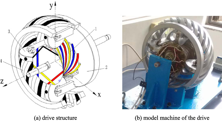
Toroidal electromechanical drive.
The planets and the outer stator adopt permanent magnets for magnetic field excitation, and the coils in the worm inner stator are connected to three-phase alternating-current supply for a rotating magnetic field. Due to the shape of the inner stator, the rotating magnetic field is toroidal along spatial armature coils. Once the magnetic force acting on the permanent teeth of the planets, the planets will be easily driven, and the rotor will also be driven at the same time. When specific structure parameter relationship is satisfied between the planet pitch, helical angles of the two stators and the number of pole pairs of central worm, the N pole of one element will be able to correspond to S pole of the other elements. The electromagnetic forces between N and S pole of different elements are the driving forces for toroidal electromechanical drive. It will drive the rotor with the planets to rotate around their own axis. The kinematic relation between rotating magnetic field and planets is similar to planetary drives. Thus, the output with low speed and large torque is achieved. Essentially, the toroidal electromechanical drive is equivalent to one motor plus one drive system.
Based on the transmission principle, let ω
r
denote output angular speed of the rotor, the toroidal electromechanical drive can be converted into a fixed axis gear train after adding a common speed −ω
r
to the whole drive system. The speed ratio between the outer stator and planet in the coordinate system attached to the rotor of the drive can be expressed as
Combining the Eqs (1) and (2), the speed ratio between the rotating magnetic field and the rotor can be calculated as
From Eq. (4), it is known that the speed ratio of the drive is always an even number, and the speed ratio is only decided by n which is related to the tooth number of the outer stator. The difference of speed ratio between the same and opposed direction of helix angles for the two stators is 2. In order to obtain larger speed ratio of the drive, the helix directions of the two stators will be designed opposed to each other.

The tooth number of outer stator.
A model machine of the toroidal electromechanical drive has been manufactured as shown in Fig. 1(b), and the preliminary test of rotational speed ratio has been completed and verified. In the test, the speed fluctuation of the rotor was observed. It indicated the existence of the torque fluctuation in the running of the toroidal electromechanical drive. To improve the steady-state output performance of the toroidal electromechanical drive, it is necessary to analyze the electromagnetic torque of the drive system.
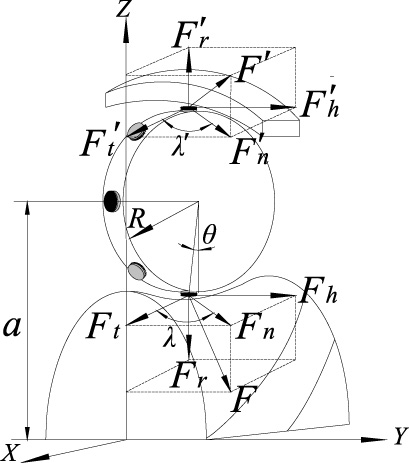
Forces in the drive system.
In the toroidal electromechanical drive, the teeth on planets are mounted in pairs. For the convenience, the forces between one pair of teeth on the planet and the two stators in mesh at any rotated angle θ of planet are shown in Fig. 3. F denotes the total magnetic force between the worm inner stator and the planet tooth, and F
t
, F
r
and F
a
are the tangential, radial and axial components of the total magnetic force, respectively. F′ denotes the total magnetic force between the planet tooth and the outer stator with tangential, radial and axial components which were expressed as F′
t
, F′
r
and
In the toroidal electromechanical drive, the rotor is driven by the revolution of the planets. The rotations of the planets around their own axes obey the equilibrium theory. We have
The lead angles of the worm inner stator and the outer stator are related to the position angle θ
i
, the relations can be given as
By substituting Eq. (9) into Eq. (10), the electromagnetic torque can be obtained
Combining Eqs (6), (8), (9) and (11), the electromagnetic torque along with the rotating angle of planet for the drive system can be given as
In Eq. (12), it is known that the output torque of the drive system is related to the structural and electromagnetic parameters. There are linear relationships between torque and electromagnetic parameters. The tooth number of the outer stator also has linear relationship with output torque. Among other structural parameters, the number of planet teeth in mesh with the worm inner stator is an important impact factor needed to be further analyzed.
The output torque of the toroidal electromechanical drive is affected greatly by the planet teeth in mesh which is related to the tooth number of planet and the face width angle of the worm inner stator. During the rotation of the planets, the output torque produced by different magnetic tooth on planets is different. There are periodic changes in output torque because the number of tooth pairs in mesh and the position relationships between the teeth are the same as the initial position when the planets rotate one angular pitch. Take one planet as example, the initial positions of planet teeth and the serial number for every tooth are shown in Fig. 4.

The initial positions of plant teeth.
Let 𝛼 denote the face width angle of the worm inner stator, and 𝛼0 denote the angular pitch of the planet. Under z 3 = 8, the output torque of the drive system with different number of planet teeth in mesh with the worm inner stator can be analyzed as below:
Under 45° < 𝛼 < 90°, starting from the initial position, there is m = int(𝛼∕𝛼0) = 1 (here, 𝛼0 = 45°) magnetic tooth of planet in mesh at the throat of the worm, and then the output torque can be obtained as T = f (θ). After a rotating angle of ((m + 1)𝛼0 −𝛼)∕2, the output torque is T = f (θ) + f (θ − 𝛼0) with m + 1 magnetic teeth in mesh. After a rotating angle of 𝛼∕2, there is m = 1 magnetic tooth in mesh, and the output torque is T = f (θ − 𝛼0) until the end of rotating angle period 𝛼0. Under 𝛼 = 90°, there are always m = 𝛼∕𝛼0 = 2 magnetic teeth of planet in mesh, because when a planet tooth is out of the electromagnetic meshing from the face width angle of the worm, another planet tooth just enter the face width angle into mesh, the output torque is T = f (θ) + f (θ − 𝛼0) in the whole rotating angle period. Under 90° < 𝛼 < 135°, there are m = int(𝛼∕𝛼0) + 1 = 3 magnetic teeth in mesh at the beginning, and the output torque is T = f (θ − 𝛼0) + f (θ) + f (θ + 𝛼0). After a rotating angle of (𝛼 − (m −1)𝛼0)∕2, there are m − 1 planet magnetic teeth in mesh, and the output torque is T = f (θ) + f (θ − 𝛼0). After a rotation angle of ((m + 1)𝛼0 − 𝛼)∕2, the output torque is T = f (θ) + f (θ − 𝛼0) + f (θ − 2𝛼0) with m magnetic teeth in mesh until the end of rotating angle period. Under 𝛼 = 135°, there are m = 𝛼∕𝛼0 = 3 magnetic teeth of planet in mesh, and the output torque is T = f (θ − 𝛼0) + f (θ) + f (θ + 𝛼0). After a rotation angle of 𝛼0∕2, there are still m planet magnetic teeth in mesh, but the output torque is calculated as T = f (θ) + f (θ − 𝛼0) + f (θ − 2𝛼0) until the end of period. Under 135° < 𝛼 < 180°, similarly, there are m = int(𝛼∕𝛼0) = 3 magnetic teeth in mesh at the start, which corresponding to the output torque T = f (θ − 𝛼0) + f (θ) + f (θ + 𝛼0). After a rotation angle of ((m + 1)𝛼0 − 𝛼)∕2, the output torque can be given as T = f (θ + 𝛼0) + f (θ) + f (θ − 𝛼0) + f (θ −2𝛼0). After (𝛼 − (m −1)𝛼0)∕2, the output torque is T = f (θ) + f (θ − 𝛼0) + f (θ − 2𝛼0) until the end of period.
Based on above analysis, the changes of the output torque along with the rotating angle for toroidal electromechanical drive are summarized as four cases:
(a) if the face width angle of the worm inner stator is not divisible by the angular pitch of the planet, and the quotient is an odd number, take m = int(𝛼∕𝛼0), then the output torque along with the rotating angle can be given as
(b) if the face width angle of the worm inner stator is not divisible by the angular pitch of the planet either, but the quotient is an even number, take m = int(𝛼∕𝛼0) + 1, then the output torque can be given as
(c) if the face width angle of the worm inner stator is divisible by the angular pitch of the planet, and the quotient is an odd number, take m = 𝛼∕𝛼0, then the output torque is given as
(d) if the face width angle of the worm inner stator is also divisible by the angular pitch of the planet, but the quotient is an even number, take m = 𝛼∕𝛼0, then the output torque is given as
The planets have N and S polar permanent magnets mounted alternately as teeth in mesh. So the planet tooth number is always an even number. More permanent magnetic teeth on the planets can improve the performance of the drive system. However, the size of the planets is limited, and then limited planet tooth number could be selected. Frequent planet tooth number for the planet is 8, 10, 12 and 16. Thus all of the output torques along with the rotating angle under z 3 = 8, 10, 12 and 16 can be analyzed by using Eqs (13)–(16). Here, taking z 1 = 12 as an example to illustrate the analytic result.
Under z 3 = 12, here 𝛼0 = 30°, the output torque of the drive system with different number of planet teeth in mesh with the worm inner stator can be analyzed as below:
Under 60° < 𝛼 < 90°, m = int(𝛼∕𝛼0) + 1 = 3, and this face width angle interval belongs to case b. Starting from the initial position, there are m = 3 planet magnetic teeth in mesh, then the output torque is Under 𝛼 = 90°, m = 𝛼∕𝛼0 = 3, and this face width angle interval belongs to case c. The output torque is Under 90° < 𝛼 < 120°, m = int(𝛼∕𝛼0) = 3, and this face width angle interval belongs to case a. The output torque is Under 𝛼 = 120°, m = 𝛼∕𝛼0 = 4, and this face width angle interval belongs to case d. There are always m = 4 planet magnetic teeth in mesh, and the output torque is Under 120° < 𝛼 < 150°, m = int(𝛼∕𝛼0) + 1 = 5, and the face width angle interval belongs to case b. There are m = 5 planet magnetic teeth in mesh from the initial position, and the output torque is
Results of output torque
Equations (9)–(12) can be used to calculate the output torque of the toroidal electromechanical drive with any tooth number of the planet and any face width angle of the worm inner stator.
Under face width angle of the worm 𝛼 = 80°, output torques along with the rotating angle are shown in Fig. 5(a) (z 3 = 8) and Fig. 6(a) (z 3 = 12). Under 𝛼 = 90°, output torques are shown in Fig. 5(b) (z 3 = 8) and Fig. 6(b) (z 3 = 12). Under 𝛼 = 100°, output torques are shown in Fig. 5(c) (z 3 = 8) and Fig. 6(c) (z 3 = 12). Output torques under 𝛼 = 110° are shown in Fig. 5(d) (z 3 = 8) and Fig. 6(d) (z 3 = 12). Output torques under 𝛼 = 135° are shown in Fig. 5(e) (z 3 = 8) and Fig. 6(e) (z 3 = 12). Under 𝛼 = 140°, output torques are shown in Fig. 5(f) (z 3 = 8) and Fig. 6(f) (z 3 = 12). Other parameter values used in the following calculations are presented as shown in Table 1.
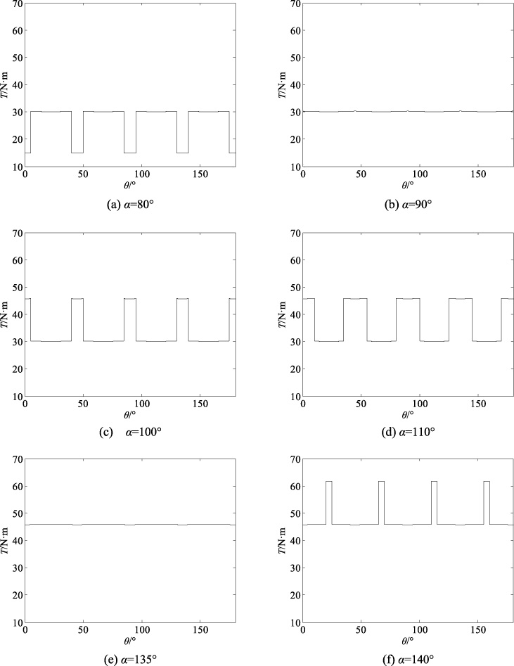
Changes of output torque along with rotation angle under z 3 = 8.
Parameter values used in the calculations

Changes of output torque along with rotation angle under z 3 = 12.
From Figs 5 and 6, it is known:
There are periodic changes in output torque. The periods are decided by tooth number of the planet, because there are periodic changes of tooth pair number in mesh between planets and worm inner stator when the planets rotate one angular pitch. The output torque changes are pulsed when the face width angle of the worm inner stator is not divisible by the angular pitch of the planet. The output torque changes are continuous when the face width angle of the worm inner stator is divisible by the angular pitch of planet. The face width angle of the worm inner stator has significant effect on output torque amplitude under the same planet tooth number. As the face width angle increases, the output torque increases with more tooth pairs in mesh. In the pulsed changes of output torque, the changes caused by the number of tooth pairs in mesh are the main causes for the pulsed torque. By contrast, the changes caused only by the rotation angle of the planets can be neglected. Under the same face width angle of the worm inner stator, as the tooth number of the planet increases, the output torque increases slightly. It is because the output torque produced by single tooth pair in mesh decrease, which partially counteract the increases of the number of mesh tooth pairs. In order to get less fluctuation and larger output torque, the selected face width angle of the worm should be lager and divisible by the angular pitch of the planet.
From above analysis about the periodic changes of output torque for toroidal electromechanical drive, it is known that the tooth number in mesh during the operation of the drive causes the fluctuation of the output torque. In order to describe the fluctuation characteristic under different structural parameters quantitatively, the coefficient of fluctuation can be defined as
Equations (18)–(20) can be used to calculate the fluctuation ratio for toroidal electromechanical drive with any tooth number of planet and any face width angle of the worm inner stator. Under the situation of pulsed torque changes. Here, taking z 3 = 8 and z 3 = 12 as example to contrast and analysis, the torque fluctuation ratio along with the face width angle of the worm inner stator is shown in Fig. 7. Under the situation of continuous torque changes, the calculation results of torque fluctuation ratio under 𝛼∕𝛼0 = 2 and 𝛼∕𝛼0 = 3 are given in Tables 2 and 3, respectively.
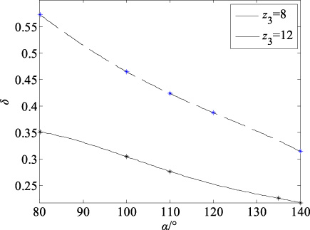
Torque fluctuation ratio along with the face width angle of the worm.
Calculation results of torque fluctuation ratio under 𝛼∕𝛼0 = 2
Calculation results of torque fluctuation ratio under 𝛼∕𝛼0 = 3
From above analysis and calculation about torque fluctuation, it is known:
Compared to the pulsed mode of output torques, the fluctuation ratios of continuous torque changes decrease substantially, and they can be nearly neglected when it is necessary. The face width angle of the worm inner stator has evident influence on fluctuation ratio. As the face width angle increases, the torque fluctuation ratio decreases under the same planet tooth number. It is because the mean output torque increases with more tooth pairs in mesh. The tooth number of planet has also significant influence on fluctuation ratio. Under the same face width angle of the worm inner stator, the differences between the maximum and minimum output torque decrease with more teeth in mesh. In the continuous mode of output torque, the fluctuation ratios decrease as 𝛼∕𝛼0 increases under same tooth number of the planet. It is because there are more tooth pairs in mesh with higher 𝛼∕𝛼0. As the tooth number increases, the fluctuation ratios decrease obviously with smaller face width angle of the worm inner stator under the same 𝛼∕𝛼0.
These results would be used to select the structural parameters of toroidal electromechanical drive for its special torque fluctuation characteristic. Considering the cost of actual manufacturing, Fig. 8 shows the optimal fluctuation along with rotating angle under the situation that the face width angle of the worm is 90°. In Fig. 8, figure (a) shows the torque fluctuation with z 3 = 8 which includes two periodic changes in output torque, figure (b) shows the torque fluctuation with z 3 = 12 which includes three periodic changes in output torque. It is clearly that the output torque increases slightly and the torque fluctuation characteristic is improved obviously in the cost of manufacture.

Torque fluctuation along with rotation angle under 𝛼 = 90°.
In this paper, the torque fluctuation characteristic of toroidal electromechanical drive is analyzed. Based on the principle of electromagnetic drive, the electromechanical coupled forces between the two stators and the planet are presented, and the output torque equation is deduced for the drive system. Besides electromagnetic parameters, the output torque is influenced by mechanical parameters and position parameter of planet. Changes of the output torque along with the rotating angle for the drive system are classified into four cases. Under different cases, equations of the output torques are given. The output torque with different structural parameters is analyzed. The periodic torque changes caused by the number of mesh tooth pairs are pulsed mode and continuous mode. The fluctuation characteristics of the two modes are analyzed quantitatively. The results show that the torque value increases slightly with the tooth number of planet increases, however, the fluctuation characteristic of the drive system is evidently improved under both modes. The face width angle of the worm inner stator has obvious effect on output torque amplitude and fluctuation ratio. In order to obtain continuous output torque with less fluctuation, a relation should be met between face width angle of the worm and tooth number of the planet.
Footnotes
Acknowledgements
This work is supported by the National Natural Science Foundation of China (Grant No. 51875408), and the State Foundation for Studying Abroad of China Scholarship Council, and National Natural Science Foundation of China (Grant No. 51575390).