



Abstract
Permanent magnet synchronous linear motors (PMSLMs) have been widely used in industry applications due to their outstanding dynamic characteristics and improved servo-capability. However, the detent force of PMSLM is an inevitable problem, which causes vibration and affects the positional accuracy of the machine. An improved PMSLM structure with arc-teeth and inner-ladder end teeth (AIL-teeth) is proposed in this study to reduce detent force. This structure is advantageous because it not only reduces detent force but also keeps motor size constant. First, the parameters that affect detent force are confirmed using Fourier analysis method. Second, a hybrid optimization method is adopted to obtain the structural parameters of the AIL-teeth PMSLM. The hybrid optimization method is based on the flux-tube and Taguchi methods. The optimal structural parameters of the AIL-teeth PMSLM are determined using the optimization method. Finally, two PMSLMs with traditional and improved structures are contrasted by finite-element analysis (FEA) method and experimental verification, results show that the improved AIL-teeth PMSLM can reduce detent force effectively with the least sacrifice of electromagnetic performance.
Introduction
With the rapid development of mechanical and electrical products toward high-efficiency and high-precision direction, permanent magnet synchronous linear motors (PMSLM) direct-drive technology has become one of the most representative advanced technologies. PMSLM can provide a direct linear drive without any intermediate transmission links, which has outstanding advantages of high thrust, fast response, energy saving, maintenance free advantages etc. [1–3]. However, the detent force, which consists of end effect and cogging forces, is an obvious drawback, which causes mechanical vibration, acoustic noise, and velocity oscillation, for the application of PMSLMs [4,5].
Several novel structures and optimization methods have been employed to settle the problem and the effect is great. In [6], a new shaped magnet pole is proposed for minimizing the cogging torque of permanent magnet synchronous motor, a subdomain method is adopted to analyze models of three different magnet shapes, and the analytical results are validated by finite element analysis (FEA) method. In [7], detent force is reduced through adding auxiliary poles. Different parameters of auxiliary poles are researched, and the response surface method is used to obtain the final structure of PMSLM. In [8], novel auxiliary teeth with stair shaped are proposed to minimize the end edge detent force on discontinuous armature PMSLMs, and Taguchi’s design method is used to optimize the stair-shape auxiliary teeth. In [9], slot-phased shift method is adopted to minimize the detent force for a 6/4 double-sided interior permanent magnet flat linear brushless motor. Fourier series are used to analyze the motor and thrust force is calculated. The results are compared with the 3D FEA method. In [10], a novel double-stator permanent magnet linear motor is used in artificial hearts. When the electrical angle difference between the inner stator and the outer stator is 90°, the cogging force can be counteracted mutually. In [11,12], an orthogonal structure is applied to a PMLM to reduce the cogging force, in which the end effects are considered. At the same time, response surface method is used to optimize the motor structure. In [13], a PMSLM with 1000 N thrust force is developed, and three design approaches, namely, using arc-shape magnet outer face, narrowing the slot opening, and adding an auxiliary tooth to the end region of the motor, are used to minimize the force ripple. The FEA method is used to analyze the design features, and results are accurate. In [14], the response surface methodology (RSM) and FEA method are adopted to optimize the motor for maximum torque density, the final structure parameters are determined by a central composite design method, and the results are verified by test. In [15], a dynamic dual-RSM model is proposed to optimize the design of PM motors, the FEA method is used to calculate the objective function, a radial basis function and a moving least-square approximation method are adopted to establish the dual-RSM model, and the optimal results are compared with the FEA computation. In [16,17], the RSM and improved simplex method are used to minimize the cogging force of interior PM motors, and the results are tested by the FEA method. In [18], the fuzzy-based Taguchi method and Rosen Brock’s algorithm are used to design an interior PMSM to minimum cogging torque and maximum average torque. The optimization results are validated by experimental measurements. In [19–23] a new technology with skewing is adopted to reduce torque ripped, stepped rotor skewing, stator poles skewing, and pole-shoe skewing are respectively used to analyze the influence on cogging torque, and skew angle is determined by simulation. In [24–27] end effect problems are considered, a nonlinear equivalent magnetic network model, genetic algorithm and FEA method are used to reduce the detent force which caused by the end effect, the accuracy of the proposed method is verified by the simulation and experimental.
Comparing the aforementioned methods, Taguchi optimization method does not need to use complicated algorithms and additional programming, and many parameters in design optimization can be optimized simultaneously, therefore, it is useful in designing PMLSM [17]. In addition, in the above-mentioned novel structure, detent force is minimized by increasing motor length, which increases the quality and cost of the motor. In this paper, an improved structure of arc-teeth and inner-ladder end teeth (AIL-teeth) PMSLM is proposed, detent force is minimized, and the motor size is kept the same. First, the Fourier analysis method is used to determine the parameters that influence detent force. Secondly, flux-tube method is adopted in consideration of time consumption to calculate the initial structural parameter of the arc-teeth height. On this basis, the Taguchi method with FEA method is used to ensure the inner-ladder end teeth dimension, and then the final parameters of the AIL-PMLSM are determined. Finally, two different structures of PMSLMs with traditional motor and improved motor are compared using the FEA method and a prototype is manufactured and tested, the results show that the proposed AIL-teeth PMSLM can reduce the detent force valid.
Description and configuration of Arc-teeth PMLSM
Structures of the traditional PMSLM and the improved AIL-teeth PMSLM are shown in Fig. 1(a) and Fig. 1(b), respectively. Fractional slot concentrated winding form is adopted in the 11-pole/12-slot AIL-teeth PMSLM. Permanent magnets are arranged on the back iron surface alternately. The x axle represents the distance between the centerline of the arc-tooth and the permanent magnet poles.
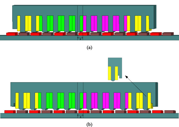
Two different structures of permanent magnet synchronous linear motors: (a) Traditional structure of PMSLM; (b) Improved structure of PMSLM.
Detent force is an inherent characteristic of a PMLSM and the main cause of thrust ripple. Detent force consists of two elements; one is the cogging force caused by the interaction between the PM and primary teeth, and the other one is the end-effect force. The end-effect is produced by the disconnected end of secondary and the limited length of primary. Therefore, the detent force can be decreased by minimizing cogging force and end-effect forces.
Fourier analysis of the cogging force
The cogging force is generated by the interaction between PMs and stator teeth under no-load condition. On the basis of the virtual power method, the cogging force formulation is defined as follows [28]:
The permeability of the stator and back-iron are assumed to be infinite, and the magnetic field energy is approximately the sum of the air-gap energy and PMs energy. The formulation is expressed as:
Equation (2) can be expanded in accordance with the Fourier series method, Eq. (2) is integrated into Eq. (1), and the detent force expression can be deduced as follows:
Equation (3) indicates that the cogging force is affected by the effective length of air-gap. Thus, the arc-teeth structure is adopted to minimize the cogging force as shown in Fig. 1(b). The length of air-gap can be modified by adjusting the height of arc teeth.
The end effect force is caused by the mutual attraction between the end teeth and PM, and the expressions of forces on the left and right sides are defined as follows [29]:
In this paper, a special design technique with inner ladder- auxiliary teeth is used to reduce the value of end-effect force, and the detail structure is also shown in Fig. 1(b).
Design optimization of the PMLSM is a complex process, it converts the engineering design problems into optimal problems. Selecting a reasonable optimization method can save time and improve efficiency. In this paper, a hybrid optimization method is applied in AIL-teeth PMSLM, five main optimal variables of motor design are selected and shown in Table 1, and the minimum detent force is the optimization objective. The optimization procedure is divided into two steps: First, the flux-tube method is adopted to optimize the height of the arc-teeth without auxiliary teeth considering the time consumption and simplified computational complexity. Second, based on the optimized arc-teeth height, Taguchi and FEA methods are adopted to optimize other variables for obtaining the optimal structure parameters of the AIL-teeth PMSLM.
Five main structure variable of AIL-teeth PMSLM
Five main structure variable of AIL-teeth PMSLM
The flux-tube method has been widely used in the initial design of electric machine [30–32], compared with the FEA method, this method takes less time and is sufficient to predict the reluctance of air gap that influences cogging force.
Flux-tube method
The flux distribution of the AIL-teeth PMSLM without auxiliary teeth obtained by FEA method is shown in Fig. 2(a). Four situations need to be considered to calculate the flux distribution of air gap in different positions under a pole pitch, and flux tubes that connect one stator and one PM pole are displayed in Fig. 2(b). The shadow area is the infinitesimal element of flux tube. The red dotted line area represents the leakage of magnetic flux, and the black solid area from −X m to X m represents the main magnetic flux.
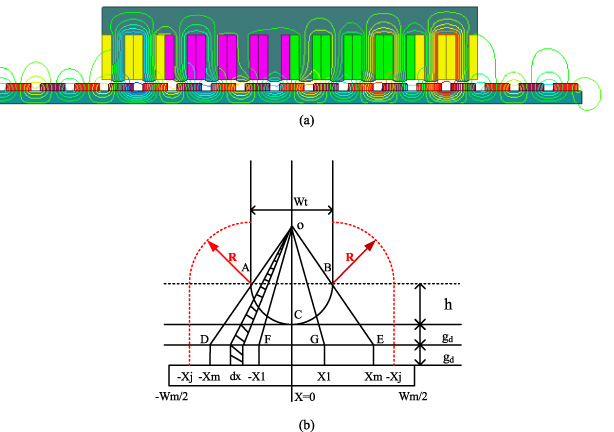
Distribution of flux and flux tube model of AIL-teeth PMSLM: (a) Distribution of flux from FEA simulation; (b) Flux tube model of the AIL-teeth PMSLM.
(1) Aligned : 0 ≤ x ≤−w m ∕2 + X j
When the arc-tooth and the PM Pole are aligned, the radiation area of magnetic flux is from −X
m
to X
m
, the permeance of air-gap formulation is expressed as follows:
(2) Unaligned : −w m ∕2 + X j ≤ x ≤−w m ∕2 + X j + X m
When the permanent magnet pole moves along the x axis, the mover position is between −X
j
and −X
m
, the permeance of air-gap formulation is described as follows:
(3) Unaligned : −w m ∕2 + X 1 ≤ x ≤ w m ∕2 + X m
When the permanent magnet pole moves away the area of leakage flux into the main magnetic flux area of arc-tooth, the radiation area of flux tube is from −X
1 to X
j
, the permeance of air-gap formulation is described as follows:
(4) Unaligned : −w m ∕2 + X m ≤ x ≤ w m ∕2 + X j
When the PM pole moves to the right of the stator teeth, the radiation area of magnetic flux area is from X
m
to X
j
, the permeance of air-gap formulation is described as follows:
Due to above permeance values, the flux linkage can be calculated and the detent force of AIL-teeth PMLSM can be derived as follows:
According to calculate the Eq. (12), the minimum detent force without auxiliary teeth can be obtain. Figure 3 shows the calculate results using flux-tube method, it indicated that with the increase in height (h), the detent force first decreases and then increases. The minimum detent force is at 0.85 mm, and the peak-to-peak value is 26.3 N.
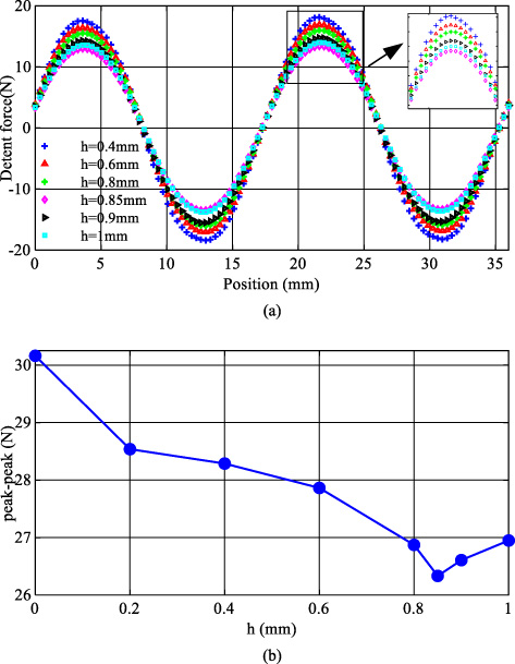
Relationship between h and detent force: (a) Distribution of detent force; (b) Detent force vary with the height of arc-teeth.
Taguchi method is a local optimization method, which combines the orthogonal table to select the experimental conditions and arrange the experiment. The characteristics of this method is that the optimal design of a motor can be achieved through the best combination of design parameters and with the minimum number of experiments.
In this section, Taguchi and FEA methods are combined to optimize the structure parameters of inner-ladder end-teeth. The length and width of auxiliary teeth and inner-ladder teeth are determined as the optimize parameters, and the minimum detent force and maximum thrust force are taken as the optimization objective. The expression of detent force and thrust force for the FEA can be obtained as follows [33]:
The framework of Taguchi optimization method is given in Fig. 4.
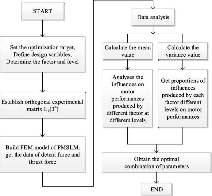
Framework of Taguchi optimization method.
Optimized parameters and the level table of the AIL-teeth PMSLM are given in Table 2.
Optimization variables and factor level of AIL-teeth PMSLM
In the traditional design method of PMLSM, 81 times are need to be calculated in above parameters. However, the experimental matrix established using Taguchi method with FEA only needs to be calculated 9 times. The orthogonal experimental arrays L9 are displayed in Table 3.
Orthogonal experimental arrays with FEA method
In order to analysis the influences of different level parameters on the detent force and thrust force, the mean value of each performance at whole level and each level are need to be calculated respectively, as shown in Table 4 and Table 5.
Average values of each performance in motor
Average values of performance in each level
Table 5 presents that two combination parameters can satisfy the optimization requirements, the best combination for minimum the detent force is X
i
(3) Y
i
(1) f
x
(3) f
y
(2), and the maximum thrust force is X
i
(1) Y
i
(1) f
x
(1) f
y
(3). Therefore, variance is used to evaluated the effect of parameters on motor performances. The formulation of variance can be calculated as follows:
According to the value of mean and variance, the main factor effect on the AIL-teeth PMLSM in different performance is shown in Fig. 5 and the corresponding proportion is given in Table 6.
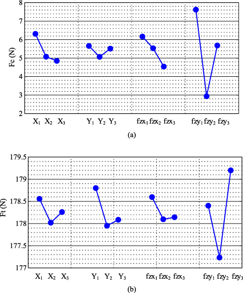
Distribute of the parameter effects on AIL-teeth PMLSM: (a) different parameters effect on cogging force; (b) different parameters effect on thrust force.
Variance and ratio of performance for parameters
Table 6 implies that the f y affect F c and F t obviously, F t has a relative influence on X i , and Y i , f x exerts a weak effect on the F c . The final structure parameters of the AIL-teeth are determined from the Table 5 and Table 6, as shown in Table 7.
Level combination and value of each parameter for optimal scheme
According to the combined parameters in Table 7, the distribution of detent force is obtained as shown in Fig.6:
In this section, in order to confirm and assess the merits of the proposed AIL-teeth PMSLM, the FEA method and experiment test are adopted to analysis the performance of two PMSLMs.
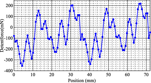
Distribution of the detent force based on Taguchi method.
According to the Fig. 1(a), a traditional PMSLM is manufactured. The mover yoke of the PMSLM is laminated by 0.5 mm silicon steel sheet. The material of the stator back iron is No. 10 steel, and the permanent magnet mounted on the stator is NdFe35. The experiment platform is shown in Fig. 7.
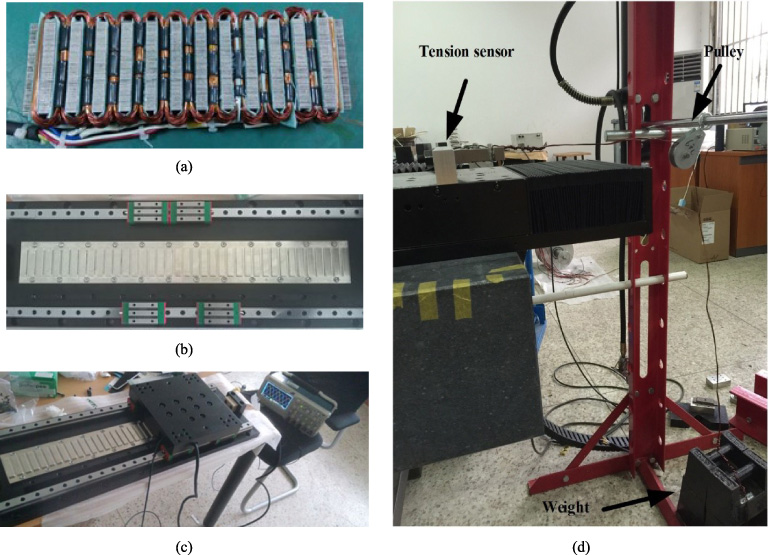
Prototype and experiment of PMSLM: (a) Stator of PMSLM; (b) Mover of PMSLM; (c) Experiment of back EMF in PMSLM; (d) Device for measure force.
Four different velocities are selected for measurement to improve the accuracy of the experimental results. The experimental results are shown in Fig. 8, the waveform of electromotive force (EMF) has a good sinusoidal property with different velocities. The maximum value of EMF at synchronous speed is about 53 V.
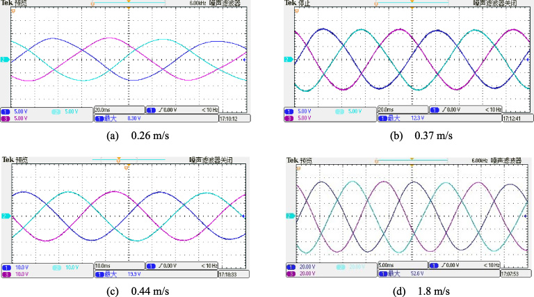
EMF experiment of PMSLM: (a) experiment waveform of 0.26 m/s; (b) experiment waveform of 0.37 m/s; (c) experiment waveform of 0.44 m/s; (d) experiment waveform of 1.8 m/s.
Tension sensor is used to measure the detent force and thrust force, the measuring range is 300 N, and the amplifier outputs 12 V at full range. In the Fig. 9, channel 1 is the output waveform of the tension sensor, and channel 2 is the waveform of the B phase EMF, the value is 8.3 V. The peak-to-peak value of the output waveform of the tension sensor is 120 mV, and the corresponding amplitude of the detent force is 3 N.

Experiment waveform of detent force.
A controller is adopted to control the motor for performing a uniform motion to measure the electromagnetic thrust of the motor. Figure 10 shows the experimental waveform of thrust force, channel 1 is A phase current, the value is 7 A, and channel 2 is the output voltage of the tension sensor, the thrust force is approximately 200 N.

Experiment waveform of thrust force.
The comparison between FEM and experiment is conducted with motor running at a synchronous speed of 1.8 m/s. And according to the optimized result of the flux-tube and Taguchi methods, two different structures of PMSLM are contrasted as shown in Fig. 11.
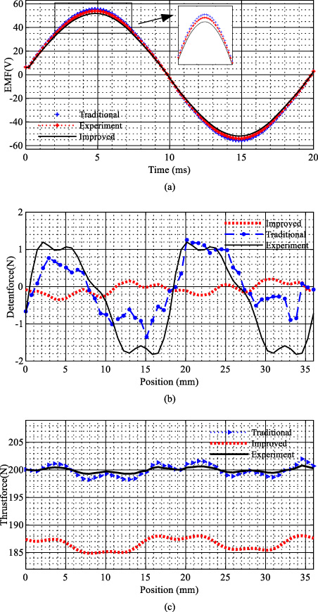
Experiment and Contrast performance characteristic of two structures: (a) Waveform of no-load back EMF; (b) Experiment waveform of detent force; (c) Experiment waveform of thrust force.
As shown in Fig. 11(a), the waveforms of no-load back-EMF are near-sinusoidal, but the maximum value is different, the maximum voltage of traditional structure is 54.68 V and the improved structure is 51.67 V. The reason for this change is that the air gap length is increased. The experimental value of traditional structure is less than 3% of FEA simulation value, which shows the accuracy of the simulation results.
The detent force comparison of two different structures of the PMSLM is shown in Fig. 11(b). The picture shows that the value and change trends of the detent force obtained by FEA simulation and experiment are similar. The improved structure reduces the peak-to-peak value of detent force from 2.89 N to 0.97 N, the reduction is due to the main harmonic components of the detent force are decreased as follows:
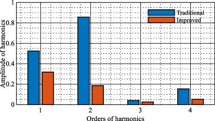
Harmonic spectra of two motors.
Figure 11(c) shows that the thrust force values of traditional structure obtained by the FEA simulation and the experiment are identical. The average thrust value is about 202 N, which demonstrates the accuracy of the FEA method. The average thrust of the proposed PMLSM is about 187 N, which is reduced 7% compared with that of the traditional PMSLM, but the detent force is reduced about 76%. Therefore, the improved structure reduced the detent force effectively.
A new type of permanent magnet linear synchronous motor with AIL-teeth is proposed and investigated. A hybrid optimize method based on flux-tube method and Taguchi method is adopted to optimize the structure parameters of AIL-teeth. Optimization results are validated by comparing with the FEA results. The performance of the traditional and improved PMSLMS is contrasted by comparing the significant data such as EMF, detent force, and thrust force The results illustrate that the motor with improved structure has a good electrical performance, and the detent force can be reduced more than 70% compare with that of the conventional structure.