
Abstract
This paper proposes a ferrofluid-based tuned mass damper with magnetic spring that is capable of absorbing the low-frequency vibration energy. The characterization and performance of the tuned mass damper are studied in theory and experiment. Ferrofluid is adhered on the moving permanent magnet and used as self-sustained viscous lubricant to reduce the mechanical damping between the permanent magnet and the inner wall of plastic tube and improve the ability of the vibration pick-up system. A magnetic spring is formed by magnetic repulsive force between the fixed and the moving permanent magnets along the horizontal axis. The tuned mass damper can effectively reduce the low frequency vibration of the rod. And the damping time in the cases of released permanent magnet is 1/6 times as long as that in the cases of blocked permanent magnet. The compact tuned mass damper with adjustable damping and stiffness is suitable to various low frequency vibrations in nature.
Introduction
Ferrofluids in a nonuniform magnetic field can behave as an elastic fluid material due to the magnetostatic force [1]. For example, ferrofluids covering on the permanent magnet (PM) can provide an elastic support and lift the PM up on the surface of the nonmagnetic substrate [2–4]. Ferrofluids are usually used as self-sustained lubricant in a damping device to reduce the mechanical damping between the PM mass and the inner wall of the nonmagnetic substrate and improve the ability of the vibration pick-up system [5]. Based on the principle of anti-resonance, vibration damping systems with ferrofluids are usually developed to dissipate vibration energy as the tuned mass damper (TMD), so the TMD with ferrofluids consists of mass block, damping component and spring. It is known that the amount of ferrofluids affect the damping character of ferrofluid-based damper. A PM, in a cylindrical nonmagnetic tube filled with ferrofluids [6], shows relatively larger viscous damping, and a PM with layer of ferrofluid absorbed, in a hollow cylindrical nonmagnetic tube, shows a small viscous damping. The PM mass with ferrofluids is usually used in the field of low frequency vibration damping due to the property of little damping and most sensitive to vibration.
During the vibration process, the vibration energy of the primary structure is partly transferred to the kinetic energy of the masses of the TMD with the changing relative velocity between the mass of the TMD and primary vibration mass. The kinetic energy of the PM mass with ferrofluids is quickly dissipated by ferrofluids, and the vibration amplitudes of the primary vibration structure decrease with itself vibration energy reducing.
It is known that the stiffness of the ferrofluids damper is limited by the restoring force. The restoring force of the ferrofluids damper is usually elastic force of ferrofluids drop on PMs [7,8] and magnetic force [1,9], which is relatively little and restrict vibration response of the mass block. To overcome this drawback, a magnetic spring can be used in the TMD with ferrofluids and provide a steady stiffness. In this paper, a novel a ferrofluid-based TMD with magnetic spring is designed and experimentally studied.
Design and model of the ferrofluid-based TMD with magnetic spring
Design of the TMD
Our early work in the literature [10] ever proposed an inertial electromagnetic generator with magnetic spring and ferrofluids to harvest the low frequency human motion energy. Here, remove the induction coils of the generator, and the remainder structure will become a compact TMD, shown in the Fig. 1(a). The mass block is composed of the kerosene-based ferrofluid (density 1.29 × 10³ kg/m3) and the cylinder NdFeB(N35) PMs with diameter of 17 mm and axial length of 24 mm. In addition, ferrofluids easily enclose on ends of the PM due to the high magnetic flux density and gradient, the PM can be suspended by the ferrofluids magnetic pressure from its two poles and move with ferrofluids together, realizing the smoothly sliding with a minimal viscous damping. The moving PM is in the non-magnetic cylindrical plastic tube with the inner diameter of 19.5 mm and axial length of 57 mm. To eliminate influence of compressing air, two ends of the non-magnetic cylindrical plastic tube are opened. The other PM with diameter of 12 mm and length of 2 mm is fixed on the nonmagnetic support pole and forms the magnetic spring with the moving PM due to the magnetic attractive force.
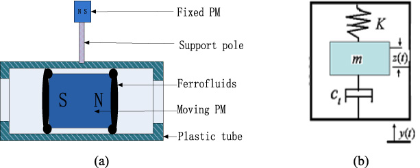
Ferrofluid-based TMD with magnetic spring (a) schematic diagram and (b) the dynamic model.
The TMD is usually considered as a single degree of freedom system shown in Fig. 1(b). The system is composed of the inertial mass m, the magnetic spring with the stiffness K and the damping coefficient C
t
. When an external excitation acts on the housing with an absolute displacement y (t), the inertial mass on the spring will move with the relative displacement z (t). The well known differential equation of the system with the resonant frequency ω
n
is described as
The total energy loss is mainly viscous dissipation of ferrofluids acting on the inner wall of the plastic tube. The damping coefficient C
t
can be confirmed by damping ratio 𝜉(= C
t
∕(2mω
n
)), and the damping ratio 𝜉 can be determined by the logarithmic decrement
It is known that the location of the PM surrounded by the ferrofluids layer affects the energy dissipation coefficient, and the energy dissipation coefficient increases with the gaps between the moving PM and the inner wall of the plastic tube decreasing [5]. The damping of the TMD can be changed by controlling the quantity of ferrofluids and the circumferential distribution positions of the fixed PM (from −90° to 90° at intervals of 45°), which can change the location of the moving PM controlled by the total external force. The total force acting on the moving PM is composed of gravity, magnetic attractive component force between two PMs in the vertical direction and magnetic support force from ferrofluid. The magnetic support force can be adjusted by the amount of the ferrofluids. Fig. 2 shows the dependence of the damping coefficient C t on the fixed PM position and the amount of the ferrofluids. It can be seen that, with the same amount of the ferrofluids of 2.2 g or 3.1 g, the damping coefficient decrease with the circumferential angle position increasing from −90° to 90°, because the gaps between the moving PM and the inner wall of the plastic tube gradually widened with the resultant force of gravity and magnetic attractive force reducing. Obviously, magnetic attractive component force and the gravity is in the same direction when the fixed PM locates at the circumferential position with angle of −90° and in the opposite direction for that with angle of 90°. Seen from the Fig. 2, the damping coefficient at the circumferential position angle from −90° to 0° decreases with the amount of ferrofluids increasing, for the gravity and the magnetic attractive component force are in the same direction and in the opposite direction with the magnetic support force from ferrofluid, respectively, which means there will be a decreasing total force with the amount of ferrofluids increasing. In addition, the damping coefficient at the circumferential position angle from 0° to 90° increases with the amount of ferrofluids increasing, for the gravity and the magnetic attractive component force are in the opposite direction and there need only a relatively small magnetic support force that can make the moving PM stable, at the same time the more ferrofluids can increase its contact area with the inner wall of the plastic tube and make the damping coefficient increase. It is shown in Fig. 2 that if the amount of ferrofluids is too small so that it can’t provide the enough large support force by ferrofluids, so there will not be a viscous damping.
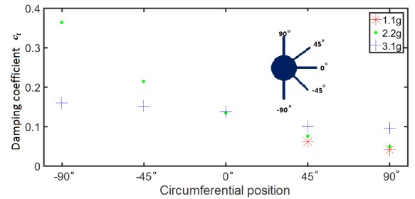
Dependence of the damping coefficient on the fixed PM position and the quantity of ferrofluids.
The equivalent magnetic spring constant K (= F∕z) is determined by the magnetic attraction F in the axial directionacting on the moving PM and the relative displacement z between the moving PM and the plastic tube. The magnetic attraction F is also seen as a restoring force to make a balance position of inertial mass in the middle of the plastic tube, which can be expressed as
Where F S and F N is the join magnetic force on the S and N poles of moving PM acted by the S and N poles of the fixed PM, respectively. 𝜇0 is vacuum permeability, d is vertical distance of the two PMs. Q (= H C A) is the magnetic field intensity with the coercive force H C and pole surface area A. a, b is half axial length of the moving PM and fixed PM, respectively. Thus the magnetic action between the two PMs works as a magnetic spring structure and is determined by the vertical distance of the two PMs d.
To obtain the magnetic spring constant K, an experimental work using spiral test frame assembled with digital push-pull gauge and calibrated scale was carried out. Figure 3 shows the graph of the total magnetic force F loading on the moving PM versus relative displacement z of the moving PM. When the moving PM is in the middle point of the plastic tube, the magnetic forces F
S
and F
N
is a couple of equal and opposite reaction force, so the total magnetic force F is zero. When the moving PM moves away from the middle position toward either end of the plastic tube with the relative displacement z increasing, the total magnetic force F increases linearly in the length of 7 mm, shown in Fig. 3. The magnetic spring constant K can be estimated as 19.17 N/m with fitting straight. The resonant frequency
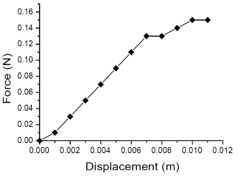
Total magnetic force vs. relative displacement between the moving PM and the plastic tube.
Figure 4(a) shows the cross sectional view of rod vibration damping systems. It is known that the plastic tube is fixed on the end of the elastic plate. The two degrees of freedom damping system consists of two masses, the primary mass and the second mass. The primary mass is mainly composed of the plastic tube, the fixed PM and the support pole. It is known that the second mass is the moving PM and ferrofluids adhering to two ends of the moving PM. And the absolute transient displacement of the primary mass is also measured by the same laser displacement sensor. The dynamical model of the vibration damping system is shown in Fig. 4(b), and the equation of the damping system is
Where x 1(t) and x 2(t) are the absolute transient displacement of the primary mass and second masses, respectively. The damping coefficient c 1 represents the energy loss of elastic plate. K 1 is the stiffness of elastic plate. f 1(t) and f 2(t) is the external force acting on the primary mass and the second mass, here, they are the gravities and can be ignored due to the larger length and little displacement of the elastic plate.
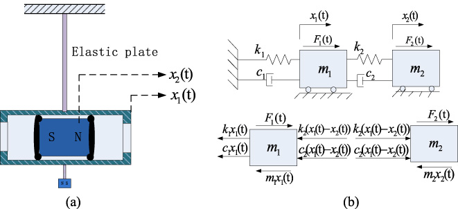
Two degrees of freedom damping system with the TMD (a) schematic diagram and (b) the dynamic model.
Two cases are developed to study the vibration damping performance of the system. In one case the moving PM is blocked, and damping energy dissipation is dominated by the elastic plate. The structure works as a normal single degree of freedom system, and the mass of the structure m includes the moving PM, ferrofluids. In the other case the moving PM is released, the structure works as the two degrees of freedom damping system with the primary mass m 1. Under the free vibration system with the initial displacement of the plastic tube of 13 mm, the moving PM oscillates out of phase with the plastic tube. It is known the maximum relative displacement (x 1(t) − x 2(t)) can be obtained at the resonance frequency, and viscous damping of ferrofluids plays a major role during the energy dissipation. The viscous damping coefficient c 2 chooses the value of 0.2146 at the circumferential position angle of −45°.
Figure 5 shows the damping performance of this TMD system. The transient displacement of the primary mass gradually decreases over time and equal zero at last. The logarithmic decrement increases from 0.03 in the blocked case to 0.4257 in the released case. The transient displacement of the primary mass in the cases of blocked PM at the time of 30 seconds is close to be equal with the transient displacement of the primary mass in the cases of released PM at the time of 5 seconds, which can be known that the damping time is cut by 25 seconds after the TMD is applied in the low frequency rod vibration. It is shown the TMD has a significant damping effect in the low frequency vibration of the rod.
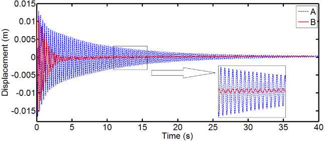
The experimental transient displacement of the primary mass in the cases of blocked PM (A) and released PM(B).
In this paper, a ferrofluid-based TMD with magnetic spring was developed and characterized. The viscous damping of ferrofluids can be adjusted by controlling the quantities of ferrofluids and the circumferential distribution of the fixed PM with the damping coefficient changing from 0.0415 to 0.3642. A special magnetic spring, magnetic attraction force between the two PMs in the axial direction was designed to provide the restoring force of the TMD, and its stiffness can be adjusted by the vertical distance of the two PMs to satisfy the demand of the resonance frequency. The TMD with ferrofluids is usually used to reduce the low frequency vibration of the rod. The logarithmic decrement increases from 0.03 in the blocked case to 0.4257 in the released case, and the damping time in the cases of released PM is about 1/6 times shorter than that in the cases of blocked PM. It is shown that the damping effect of the TMD is obvious.
Footnotes
Acknowledgements
This work has been supported by the Fundamental Research Funds for the Central Universities (2016RC010), China.