




Abstract
Considering the influence of fluid structure interaction and cavitation on the actual deformation of hydrodynamic spherical bearing, the fluid-solid coupling analysis and multiphase flow simulation of spherical bearing for multi-degree-of-freedom motors are realized in this paper. The finite element simulation analysis of the model is carried out by using multi-physical field coupling software. In the study of bearings with and without effects of cavitation, the analysis shows that the peak value of oil film pressure and elastic deformation of spherical bearing decrease when cavitation effect is considered. The oil film pressure increases with the increase of eccentricity, rotation speed, viscosity and the decrease of the clearance between stator and rotor, which improves the bearing capacity of the bearing, but also intensifies the cavitation in the oil film divergence area and increases the gas volume fraction. And the oil film pressure test platform with different rotational speeds of the spherical rotor is set up, the measured experimental data are in good agreement with the numerical results. In the practical application of the motor, appropriate parameters should be selected, which is helpful to improve the working condition of spherical bearings, ensure the stable operation of bearings and prolong the service life.
Introduction
Hydrodynamic spherical bearing is the main support component of rotating machinery. Because of its unique advantages, hydrodynamic spherical bearing is applied to liquid suspension multi-degree-of-freedom permanent magnet motors, which promotes the development of multi-degree-of-freedom motion device towards high efficiency, environmental protection and high precision positioning. The traditional multi-degree-of-freedom motor adopts mechanical devices to connect and combine, and the complex structure has serious friction and wear, low efficiency and poor reliability. The liquid-suspended multi-degree-of-freedom permanent magnet motor adopts a spherical bearing with a lubricating support structure, and the clearance between the stator with rotor is filled with lubricating oil so that the surface of the stator and rotor is not in direct contact. The oil film pressure generated by the wedge effect supports the load to realize high-precision positioning, flexible driving and zero friction operation, and ensure the reliable operation of the multi-degree-of-freedom permanent magnet motor. At the same time, the liquid suspension multi-degree-of-freedom permanent magnet motor has a wide range of application prospects in the control fields that require high-precision positioning such as robots, aerospace, and ship power systems [1–4].
The lubrication performance directly affects the service lives of motors. With the wide application of hydrodynamic spherical bearing in multi-degree-of-freedom motor, the requirements for spherical bearings to work stably and efficiently for a long time are becoming higher and higher. Considering the changes of the rotor eccentricity, rotation speed, the clearance between stator-rotor and oil film viscosity, the hydrodynamic pressure generated will change, resulting in different bearing deformation, thus also changing the fluid film flow area in the bearing. In addition, with the change of parameters, a part of the lubricating oil undergoes a phase change and becomes oil vapor, forming cavities. Cavitation in sliding bearings will accelerate wear, reduce service life and increase noise. Therefore, it is necessary to carry out fluid-solid coupling analysis of spherical bearings and study cavitation in oil film. Based on the physical model of the rotor-bearing system, some researchers carried out cavitation analysis and fluid-solid coupling analysis on bearings [5–8]. Lin et al. proposed a transient analysis method that combines computational fluid dynamics with fluid-structure interaction. The thermal and cavitation effects are studied and compared with the experimental results, which verified that the theoretical predictions are in good agreement with the experimental results [9]. Ji Hongbin et al. simulated that pressure distribution of elliptical plain bearing with and without cavitation, and analyzed the pressure field distribution of bearing under different journal rotation speed and oil supply pressure considering the influence of cavitation [10]; Dhande et al. used mixed model to model and analyze the cavitation phenomenon of sliding bearing, corrected the flow field caused by elastic deformation through parametric modeling, and optimized the design of two coupling systems based on multi-objective genetic algorithm [11]; Wang Lili et al. used Fluent two-phase flow model to analyze the oil film of three-oil groove sliding bearing under turbulent flow considering cavitation effect, and obtained the influence of different oil inlet pressure and lubricating oil viscosity on the oil film bearing capacity and cavitation [12]; Wang Rongyao et al. used finite volume method to numerically analyze two-phase flow and natural cavitation model, and obtained oil film pressure distribution and gas phase volume fraction distribution in cavitation area under different rotational speeds [13].
The above literatures are all analyzing the cavitation phenomenon of sliding bearings. At present, there is a lack of in-depth study on the cavitation and fluid-structure coupling of spherical bearings used in devices such as multi-degree-of-freedom motors. In view of the fact that the traditional hydrodynamic sliding bearing analysis method usually uses Reynolds equation finite difference method derived from Navier–Stokes equation and continuity equation, the required basic data can be obtained, but the basic assumptions in its lubrication theory limit the modeling and simulation of complex flows such as turbulence, heat transfer and cavitation. Based on the finite element multi-physical field coupling platform, this paper calculates the performance of cavitation and spherical bearing deformation caused by fluid dynamics.
Working principle of the motor and mechanism of cavitation phenomenon
The structure diagram of liquid-suspended multi-degree-of-freedom permanent magnet spherical motor is shown in Fig. 1, mainly composed of electromagnetic structure and spherical bearing structure. Figure 2(a) is a diagram of the electromagnetic structure. On the XY plane, the N and S pole tile-shaped permanent magnets with four poles alternately arranged are vertically distributed and connected by a cross-type shaft. In its tail, there is a single-pole disc-shaped fine regulating permanent magnet, and the output shaft fixedly connects two parts of the permanent magnet. There are five claw hollow coil structures on the periphery of the permanent magnet, which are distributed on the upper, lower, left, right and tail of the permanent magnets. By changing and combining the energization modes of stator coils in different directions and cooperating with permanent magnets to generate electromagnetic forces in different directions, the electromagnetic forces drive the rotor to realize multi-degree-of-freedom motion. Figure 2(b) is a diagram of the spherical bearing structure of the motor, the rotor spherical shell is a complete sphere, and the stator spherical shell has a defective spherical part, which is an incomplete sphere. The hollow rotor shell is embedded in the stator shell, and the viscous oil film is filled between two spherical surfaces. The oil film formed during the rotational movement can make the rotor suspend and automatically position. Therefore, when the motor is running, the rotor is not in direct contact with the stator, thus overcoming the influence of friction on the motion control to the greatest extent and further realizing frictionless motion.
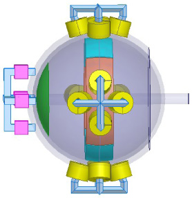
Schematic diagram of liquid suspension multi-degree-of-freedom permanent magnet motor.
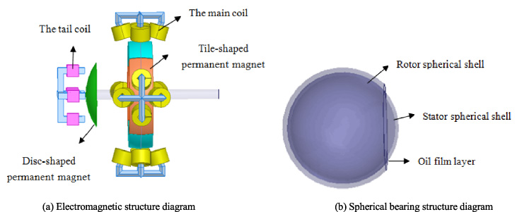
Motor stator and rotor model structure.
The stator coil of the electromagnetic structure is divided into circular hollow main coils and square hollow tail coils. In the tail coil portion, a single square coil is connected with a current of 100A, and the flux density distribution obtained by steady-state calculation is shown in Fig. 3(a). Changing the size and direction of the energizing current of the hollow coil changes the generated magnetic field as well. The tail coil is connected with currents in different directions to generate magnetic field flux density distribution in different directions as shown in Fig. 3(b). Figure 3(c) is a magnetic field streamline distribution diagram of five hollow coils. Increasing the number of coils can improve the uniformity of the magnetic field. In the main coil portion, the circular hollow main coils are respectively connected with a current of 300A, the magnetic field distribution obtained by energizing the main coil group is shown in Fig. 4(a). The magnetic field generated by the energized coil interacts with the magnetic field generated by the permanent magnet. According to the principle that the same polarity repels and the different polarities attract each other, the motor can move in multiple degrees of freedom. Figure 4(b) shows the magnetic flux density distribution obtained by permanent magnet magnetizing. Compared with Fig. 4(a), the variation of the magnetic flux density distribution of the coil is not obvious. This is mainly because the magnetic field generated by the permanent magnet is much larger than that generated by the winding of the energized coil.
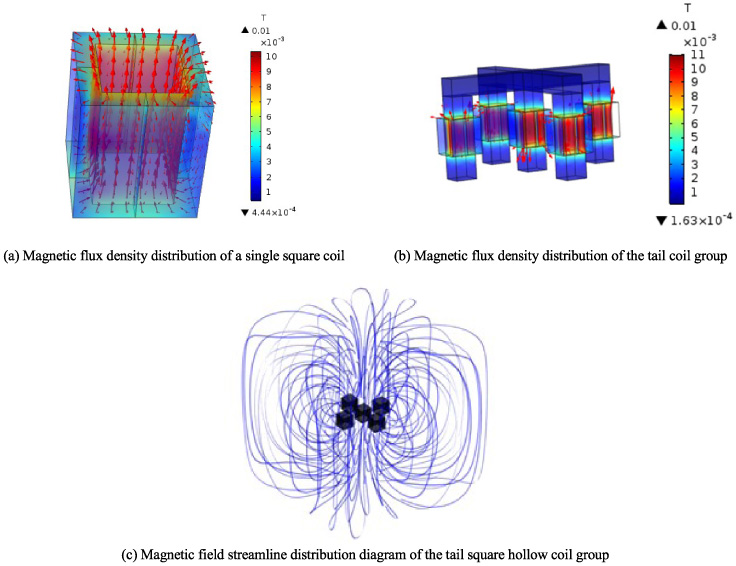
Magnetic flux density distribution of tail coil part.
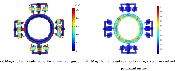
Distribution of magnetic flux density of main coil part.
In the operation of the motor, the total electromagnetic force generated by the interaction between the magnetic field obtained by coil energization and the magnetic field generated by permanent magnet magnetizing drives the rotor shell to rotate. Because the diameter of the stator shell is larger than that of the rotor shell, there is eccentricity between the rotor shell and the stationary stator shell. There are unequal gaps on the surfaces of the two spherical shells, forming convergence and divergence regions. When the rotor shell rotates in the stator shell, the adjacent lubricating oil is brought into the convergent wedge gap. Lubricating oil is squeezed to generate resistance, that is, dynamic pressure bearing capacity of oil film to separate the stator shell from the rotor shell, and support the external load, so that the friction pair is pure liquid lubrication [11]. As shown in Fig. 5, the center of the rotor shell is indicated by O 1, O is the center of the stator shell, and e 1 = OO ′′ and e 2 = O 1 O ′′ are the circumferential and axial eccentricity between the centers of the stator and rotor shells, respectively. Because the pressure of oil film in the divergent region is lower than the saturated vapor pressure of lubricating oil, the fluid is converted into steam, and the oil vapor will fill the divergent region. The appearance of holes changes the state of the flow field, which makes the oil film break naturally.

Schematic diagram of rotation model of dynamic spherical rotor in liquid.
Fluid flow equation
Considering the occurrence of cavitation, in the divergent region of spherical bearings, the oil film will naturally crack due to too much negative pressure, and lubricating oil will vaporize, thus forming gas-liquid two-phase flow [10]. However, the flow situation of two-phase flow should not only follow the basic laws of physical conservation such as continuity equations and equations of motion, but also follow the laws of mass conservation of components [14–17].
Continuity equation
The pressure distribution of hydrodynamic oil film bearing is controlled by Reynolds equation, which is derived from Navier–Stokes equation and momentum equation. According to the law of mass conservation, the continuity equation of fluid flow is deduced as follows:
In the formula,
From the momentum theorem, the equation of motion is as follows:
In the formula: n is the number of phases; the external volume force of the control body is F, N; The viscosity of the gas--liquid two phases is represented by 𝜇 m , Pa s; The slip speed of the k phase is 𝜐 dr,k , m/s; The pressure of the control body is p, N; The gravity is 𝜌 m g, N.
Due to cavitation phenomenon, the medium of the computational domain flow field changes, from single-phase flow to multiphase flow, and the transfer and transformation of matter is completed under the control equation of the conservation law of component mass.
In the formula: l and v respectively represent liquid and gas; 𝛼
v
is the volume fraction of gas phase; 𝜐
dr, v
is the gas phase sliding speed, m/s;
The fluid lubricating oil interacts with the stator shell, and the lubricating oil exerts pressure on the stator shell, which leads to the deformation of the stator shell, thus changing the flow area [7]. The finite element multi-physical field coupling simulation platform is used to analyze the deformation of the stator shell, and the governing equation is as follows:
In the formula: [M s ] is a structural quality matrix; [M f ] is the fluid mass matrix; [F s ] and [F f ] are structural and hydrodynamic matrices; [R] is a coupling matrix representing the effective surface area associated with each node in the fluid structure interface.
The relative displacement of the fluid--solid interface in the fluid domain is consistent with that in the solid domain. The thickness of lubricating oil film is defined as the distance between the rotor spherical shell-lubricating oil interface and the stator spherical shell-lubricating oil interface. The film thickness equation of spherical bearing is different from that of sliding bearing, which not only has circumferential eccentricity but also axial eccentricity. The equation is as follows:

Grid model of spherical bearing coupling system.
The structural dimensions and model parameters of spherical bearings are shown in Table 1. The model includes rotor shell, stator shell and lubricating film. Light lubricating oil is selected as lubricating oil, which is considered as incompressible. The rotor shell is running at the tangential speed of 15.7 rad/s, the stator and rotor shell are made of nylon material, and it is assumed that the spherical shell thickness is uniform. Oil film is sealed between the stator and rotor, the outer surface of the stator shell is set as a fixed boundary constraint condition. The out surface of that oil film layer and the inn surface of the stator shell are arranged as fluid--solid coupling surfaces. In the calculation, the flow field of lubricating oil is solved first. Then the fluid lubricating oil pressure obtained serves as a boundary load on the inner surface of the stator shell. The pressure is transmitted to the solid mechanics analysis module to obtain the deformation of the stator spherical shell and complete the transformation between the flow field pressure of the coupling surface and the solid deformation.

Oil film pressure test platform at different rotating speeds.
Spherical bearing structure size and model parameters
The cavitation model uses the “cavitation” interface of the ”film flow, shell“ physical field under the ”fluid flow” module of COMSOL Multiphysics software to determine the lubricating oil pressure and mass fraction. This helps to predict the formation and development of gas cavities in the lubricating layer of the bearing. Secondly, the boundary conditions in Table 1 are added, and then the model is meshed. Considering that the mesh quality has the most direct influence on the accuracy and computational efficiency of the finite element calculation, the model uses the physical field to control the mesh sequence type, and uses the triangular mesh unit to discretize the oil film region, and the element size is more refined. Among them, the grids divided in the oil inlet area of the model are relatively dense. The meshing of the coupling system of spherical bearings is shown in Fig. 6. Since the thickness dimension at the minimum oil film is small and is also an important analysis point, too small grids here will reduce the grid quality and increase the error, and too many grids will increase the calculation time, so we should choose the appropriate grid number to ensure short-term and high-precision calculation. Finally, steady-state solution is carried out and the MUMPS direct linear solver is used.

Spherical bearing pressure contour.
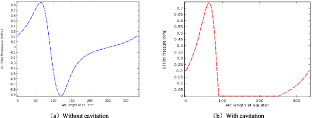
Oil film pressure distribution at equator.
The experimental device is sealed in the spherical shell of the stator by the spherical shell of the rotor. A seal ring is arranged between the two stator hemisphere shells to ensure a good sealing effect of the device as shown in Fig. 7(a). The spherical rotor is driven by means of a variable frequency motor, and the drive voltages of different frequencies are supplied to the motor by the frequency converter, so that the motor and the rotor work at different rotational speeds. As shown in Fig. 7(b), the pressure sensor mounted on spherical bearing stator housing for measuring oil film pressure in the loading area. The voltage signal outputting from the pressure sensor is connected to the data acquisition system for recording and processing as shown in Fig. 7(c). The test speed ranges from 5.6 to 31.4 rad/s, and the required speed is set with the help of the inverter. The system is allowed to achieve a steady state for half an hour and corresponding pressures is measured. Three sets of the readings were taken for each speed and the average reading is taken for the analysis. The experimental results are plotted and compared with the numerical results.
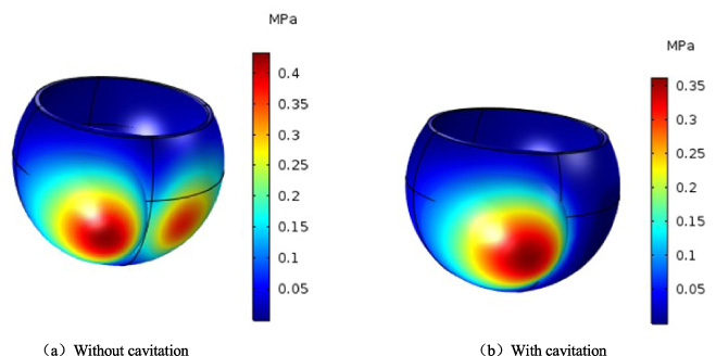
Stress and deformation distribution of spherical bearing.
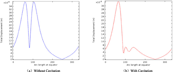
Deformation distribution of the spherical bearing at the equator.
Cavitation effect
From the above set parameters, the oil film pressure distribution with or without cavitation effect can be obtained as shown in Fig. 8. As can be seen from Fig. 8(a), the maximum pressure in the oil film bearing region is 1Mpa, while the pressure in the divergent region is equal to that in the convergent region, but negative. These negative pressures are non-physical and cannot occur in real fluids, and the oil film under negative pressure will inevitably be destroyed and cavitation phenomenon will occur, thus forming two-phase flow. As shown in Fig. 8(b), when cavitation effect is considered, the pressure distribution only has positive pressure in the convergence region. Due to cavitation, the negative pressure has disappeared and the peak pressure has changed, and the maximum value is 0.9 MPa. Theoretically, liquid lubricating oil cannot bear negative pressure, which is not in line with the actual situation, so it is more reasonable to consider the calculation results of cavitation effect. Figure 9 shows the distribution of circumferential pressure at the equator with or without cavitation effects, indicating that the peak pressure of the bearing without cavitation is greater than the peak bearing pressure with cavitation, which also proves the fact that the cavitation effect reduces the peak value of positive pressure.
Analysis of fluid--solid coupling results
Oil film cavitation can not only reflect the continuity and fluidity of lubricating oil film movement in spherical bearings, but also reflect the fluid--solid coupling relationship between oil film and stator shell when rotor shell rotates. When fluid and solid are coupled, it is mainly reflected in the change of physical quantities such as stress and displacement of solid structure. Figure 10 shows the stress and deformation distribution of oil film on stator shell with or without cavitation effect. Comparing the two figures, it can be seen that the stator shell has undergone convex deformation. However, the deformation of the spherical shell will cause the gap and eccentricity between the stator and rotor to change, thus changing the flow state of the lubricating oil and changing the oil film pressure. The change of flow field pressure causes the stress and displacement of the stator shell to change, thus forming a bidirectional fluid--solid coupling. The deformation of the stator shell considering cavitation only occurs in the convergence region, and the stress of the stator shell is less than that of the stator shell without considering cavitation. This is because the distribution of stress and strain in stator shell depends on the distribution and gradient change of oil film pressure. While the oil film pressure is relatively small when cavitation is considered. Figure 11 shows the displacement distribution of deformation at the equator of the stator shell with or without cavitation effect. It is not difficult to see that the displacement peaks of the two are different. When the arc length is 0 ∼ 100, the displacement change trend is the same. When the arc length is 100 ∼ 250, the deformation displacement of the stator shell in Fig. 11(a) presents the second peak, and the two peaks are convergence zone and divergence zone respectively. In Fig. 11(b), the displacement curve peaks in the convergence region, and two small peaks appear in the divergent region until it decreases to zero. Due to the elastic deformation of the stator shell, the gap between the stator shell and the rotor shell is increased, which makes the lubricating oil fill more space to reduce the peak value of oil film pressure generated and complete the fluid--solid coupling process. Because the bearing is damaged prematurely by the cavity, the load that can be applied to the bearing depends on the formation of the cavity.
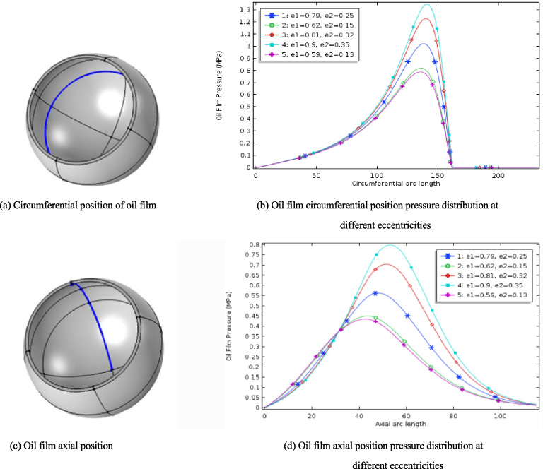
Oil film pressure distribution at different eccentricities.
Influence of eccentricity on oil film pressure
The value of eccentricity is shown in Table 2, the stator--rotor clearance is set to 78 um, and the rotor speed is 15.7 rad/s, other conditions remain unchanged, the eccentricity of the stator and rotor is changed, and the distribution of oil film pressure at the circumferential and axial positions of spherical bearings with different eccentricity is shown in Fig. 12. Figure 12(a) and (c) are the position distribution charts of the oil film respectively, and Fig. 12(b) and (d) show that the peak oil film pressure increases with the increase of circumferential and axial eccentricity. For the lower eccentricity value, the peak value is also lower. When the circumferential eccentricity is 0.79 and 0.9, the axial eccentricity is 0.25 and 0.35, the circumferential and axial pressure peaks are significant, the circumferential pressure is from 1 to 1.3 MPa, and the axial pressure is from 0.55 to 0.8 MPa. According to the variation law of the oil film pressure with different eccentricities, if eccentricity is too low, oil film pressure will also be too small, so that the stator and rotor shells cannot be separated.
Eccentricity value
Eccentricity value
When the stator--rotor clearance is 78 um, the circumferential and axial eccentricity are 0.79 and 0.25 respectively, and the rotational speeds are 5.6 rad/s, 15.7 rad/s, 21.8 rad/s and 31.4 rad/s respectively, the oil film pressure distribution at different rotational speeds at the equator is obtained. Figure 13 shows the comparison between the numerical results with the experimental results of the pressure distribution at different rotor speeds, verifying the accuracy of the numerical results and greatly shortening the calculation time. It can be seen that the peak oil film pressure increases obviously with the increase of rotor rotational speed, and the maximum oil film pressure is positively correlated with the rotor rotational speed, and the position of the peak oil film pressure at different rotational speeds is approximately the same, regardless of rotational speed.
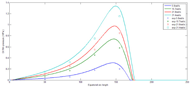
Oil film pressure distribution at the equator at different rotational speeds.
In order to study the influence of stator--rotor clearance on oil film pressure, the rotor speed is 15.7 rad/s, the stator--rotor clearances are 58 um, 68 um, 78 um and 88 um respectively, and other parameters are unchanged. The oil film pressure distribution obtained is as shown in Fig. 14. It can be known that the decrease of stator--rotor clearance will lead to the increase of oil film pressure, which is negatively correlated with each other. This phenomenon is due to the decrease of clearance causing the film thickness to decrease, and the minimum oil film thickness determines the oil film pressure peak.
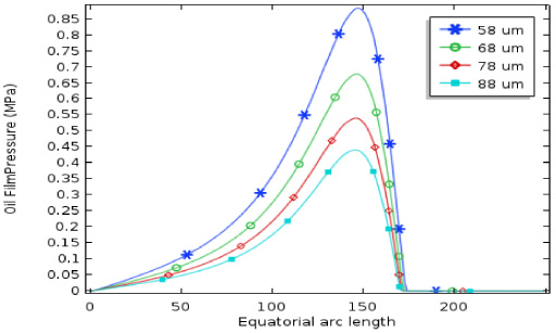
Oil film pressure distribution under different stator clearances.
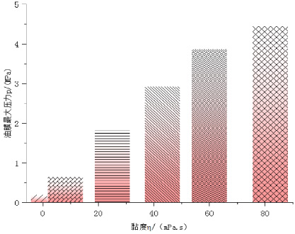
Oil film pressure distribution at different viscosities.
Figure 15 is a histogram of the maximum oil film pressure when the stator--rotor clearance is 78 um, the circumferential and axial eccentricity are 0.79 and 0.25, the rotational speed is 15.7 rad/s, and the viscosity are 0.002 Pa s, 0.008 Pa s, 0.025 Pa s, 0.043 Pa s, 0.062 Pa s and 0.082 Pa s, respectively. It can be seen that the maximum pressure of oil film presents an obvious increasing trend with the increase of the viscosity of lubricating oil. When the viscosity of lubricating oil increases from 0.008 Pa s to 0.082 Pa s, the oil film pressure increases from 0.65 MPa to 4.64 MPa, and the pressure of oil film increases by about seven times, which indicates that the higher viscosity is conducive to improving the pressure of oil film and the bearing capacity of oil film. Since the oil film pressure can not be too large or too small, the optimum range of oil film viscosity is 0.008 Pa s to 0.043 Pa s. The simulation results are plotted in Origin software.
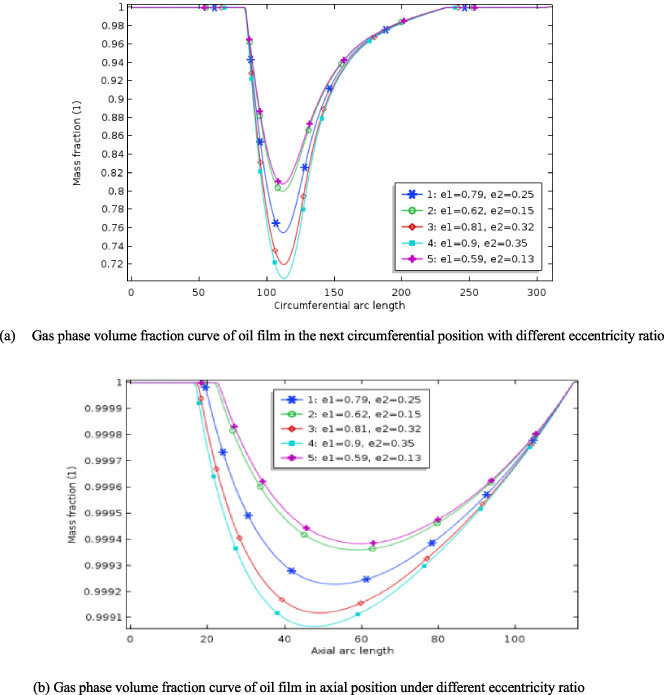
The gas phase volume fraction of the oil film at different eccentricities.
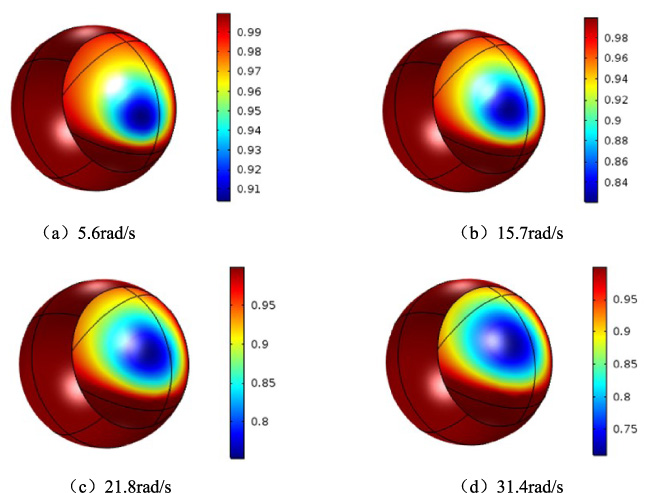
Distribution of gas phase volume fraction of oil film at different speed.
Based on the above calculation parameters, the distribution of gas phase volume fraction in cavitation region under different circumferential and axial eccentricity ratios is studied as shown in Fig. 16. With the increase of circumferential and axial eccentricity, the gas phase volume fraction increases. This is because the increase of eccentricity strengthens the oil film squeezing effect between stator and rotor, and the peak value of negative pressure increases, thus more oil vaporization is needed to offset the increased negative pressure. The vaporization area increases, and the volume fraction of gas phase will increase.
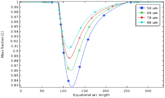
Distribution of gas phase volume fraction of oil film at different gaps.

Distribution of gas phase volume fraction of oil film at different viscosity.
As can be seen from the corresponding data in Fig. 17, cavities are distributed in divergent regions with different volume fractions. The distribution law of gas phase volume fractions of spherical bearings is the same at different rotational speeds. The volume fraction gradient is elliptic-shaped distribution, but the effect of rotational speed on the area size and position change of the cavitation area is relatively significant. The area of cavitation area increases with the increase of rotational speed, and the area of larger cavitation is gradually farther away from the bearing area to ensure the continuity of oil film in the bearing zone of spherical bearings, because the position where the oil film naturally breaks is also far away from the bearing zone.
In order to clearly and intuitively reflect the influence of stator and rotor clearance on the gas phase volume fraction of oil film, the distribution of gas phase volume fraction of oil film at different clearances at the equator is analyzed as shown in Fig. 18. The decrease of the clearance between the stator with the rotor increases the oil film pressure, but also intensifies the cavitation phenomenon. The proportion of gas volume fraction increases and the number of cavitation correspondingly increases.
Figure 19 shows the distribution of gas phase volume fraction at different viscosities. It is obvious from the diagram that the higher the viscosity of lubricating oil, the more cavitation phenomenon in the oil film divergence area will be aggravated, which will lead to the increase and expansion of the cavitation area in shape and area. When the viscosity of lubricating oil is 0.082 Pa s, the larger the cavitation area will appear in the divergence area, the gas phase volume fraction is 0.5, and when the viscosity is 0.008 Pa s, the cavitation area will be smaller and the gas phase volume fraction will be 0.75. Thus, the increase of viscosity intensifies the occurrence of cavitation phenomenon. Therefore, it is of great significance to choose lubricating oil with proper viscosity for the stable operation of the motor.
This research work is applied to the simulation analysis of the spherical bearing of the liquid suspension multi-freedom permanent magnet motor. When the cavitation effect is considered, the oil film pressure is less than that without considering the cavitation effect. The simulation result considering the cavitation effect is more reasonable.
Considering the cavitation effect, the deformation peak of the spherical bearing stator shell decreases. Considering fluid--solid coupling, the elastic deformation of the stator shell changes the flow state of the lubricant. The increase of eccentricity, rotational speed, viscosity and the reduction of stator--rotor clearance increase the maximum oil film pressure value, the negative pressure peak value and correspondingly increase the gas phase volume fraction. Eccentricity, rotational speed, stator--rotor clearance and viscosity of lubricating oil have obvious influence on the shape, size and location migration of the cavitation zone, which is conducive to ensuring the continuity of oil film in the bearing zone within a certain range and improving the lubrication quality of spherical bearings.
Footnotes
Acknowledgements
This work is supported by the National Natural Science Foundation of China (No. 51577048, 51877070, 51637001), the Natural Science Foundation of Hebei Province of China (No. E2018208155), the Overseas Students Science and Technology Activities Funding Project of Hebei Province (No. C2015003044), the Hebei Industrial Technology Research Institute of Additive Manufacturing (Hebei University of Science and Technology) open projects funding, the National Engineering Laboratory of Energy-saving Motor & Control Technique, Anhui University (No. KFKT201804), Key Project of Science and Technology Research in Hebei Provincial Colleges and Universities (ZD2018228).