
Abstract
Torque transmission along a shaft results in the shaft twisting which is negligible in the conventional motors. However, a long and thin shaft is subject to non-negligible twisting effect. This Phenomenon can affect the electromagnetic performance of the motor. In this article, the shaft twisting effect on the electromagnetic behavior of a flux-switching permanent magnet (FSPM) motor is studied. A model of an FSPM motor is proposed to study the electromagnetic performances of the motor. The electromagnetic torque and twisting rate of each point are calculated along the shaft. Then the model results are compared with finite element analysis results for a long motor.
Introduction
When torque is transmitted along a shaft, it tends to twist [1]. The twisting magnitude depends on properties and parameters of the shaft and also the transmitted torque [1]. The shaft twisting affects the electric motor behavior although it does not cause any eccentricity or the misalignment of the rotation axis whose effect on motor performance is studied in many articles [2–7]. The twisting phenomenon has already been analyzed in some mechanical articles [8–13]. However, the twisting effect on the electrical motor performance has not been investigated before. In conventional motors, the shaft twisting is negligible and usually is not observable. Three conditions should be satisfied for Shaft Twisting Effect (STE) to be observable: (1) the shaft length must be considerably longer than the shaft diameter, (2) the torque must be high enough, and (3) the motor must be sensitive to the rotor position variation. Therefore, to study the STE, a long length motor whose performance is sensitive to the rotor position is suitable. Long motors are used for some applications such as the electrical submersible pump (ESP) which aids raising oil and gas to the surface in oil wells [14]. There are at least four types of motors which are proposed for ESP application (Induction motors [15–19], Interior permanent magnet motors [17,19,20], hysteresis interior permanent magnet motors [21,22], and FSPM motors [23,24]).
The FSPM motor is a recently developed brushless permanent magnet (PM) motor [25,26]. A sample of FSPM is represented in Fig. 1. FSPM has the advantages of high torque density, high efficiency, high power factor, and easy heat dissipation [27–31]. The solid rotor increases the robustness and reliability of the motor [32]. In comparison with interior PM motors (IPM), an FSPM motor with the same pole number needs to be supplied with twice frequency to reach the same speed [27] and the proportion of the electrical to mechanical angle is twice. The twisting angle is a mechanical parameter, by contrast, the STE relates to electrical angle. Also, the FSPM motors usually have more poles since low pole number leads to some problems such as having higher harmonic components in the flux linkage and cogging torque [33] and larger torque can be obtained by motors with relatively higher rotor pole number [34]. Therefore, it seems that the FSPM motors are more sensitive to the rotor position than other types of motors. It means that STE affects the FSPM performance more considerably.
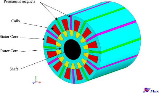
A sample of FSPM.
In this article, first, the shaft twisting phenomenon is reviewed. Twist angle depends on the applied torque and the applied torque depends on the rotor angle. Therefore, to study the STE on the electromagnetic performance of FSPM motors, a model in which the electromagnetic torque and twisting phenomenon can be considered simultaneously is required. However, traditional models cannot consider both phenomena together. Therefore, the electromagnetic equations are rewritten to provide an appropriate electromagnetic model. Finally, a typical motor is studied and the twisting effect is investigated and results of the model are compared with finite element analysis results.
According to Hooke’s law, when a force is applied to an object, it tends to deform and the size of deformation is proportional to the deforming force. For an elastic object, unless the deforming force exceeds a limit, the deformation is reversible [35]. In addition, when a circular shaft is subjected to torque, the shearing stresses occur in the cross-section of the shaft whose direction is perpendicular to the radius of the shaft at any point in the cross-section (Fig. 3) [36].
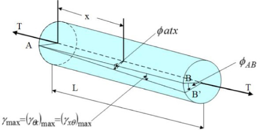
Twisted shaft.

Differential element of the shaft.
In electric motors, shafts transmit the electromagnetic torque which is produced distributary along the motor, to the load. As a result, it twists when transmits the torque and as long as the torque is lower than the maximum shear stress of the shaft, the twist is reversible. Note that the twisting does not cause eccentricity or any displacement in rotation axis. In other words, it only results in rotor position variation along the shaft (See Fig. 2). The difference between the angles of two ends of the shaft is the twist angle. The change of twist angle rate relative to the shaft length is called twist angle rate. In Fig. 2 the twist angle is illustrated as 𝜙
BA
where R, L, 𝛾, τ and G are the shaft radius, length, shear strain, shear stress and shear modulus respectively. For small angles the equations for twist angle can be written as [1]:
At the distance x from the end of the shaft:
By the use of Hooke’s shear law [1], we have:
It can be assumed that the shear stress has a linear relation with radius [1]. Therefore:
Shear stress can be calculated by ((7)) (parameters are shown in Fig. 3). Where T
in is the applied torque to the cross-section.
By considering the (3), (5) and (7), the twist angle rate is derived by (9). Therefore, twist angle can be calculated from (10) [1].
To find the twist angle, the transmitted torque along the shaft must be calculated. The twist angle causes the relative change of the rotor position around the rotation axis along the shaft.
Twisting causes electromagnetic torque variation along the shaft. Traditional 2D electromagnetic models do not consider this phenomenon. Here we propose a model by which the electromagnetic torque, transmitted torque, twist angle, and twist angle rate at any point of the rotor along the shaft can be derived. The main idea of developing this model is based on performing calculation on each differential segments along the shaft. Finding parameters of the model in each segment may be the difficult part of this modeling. However, as it is described below, the parameters are constant if the frame of the used Park transformation for each differential segment is attached to the rotor of that segment. Although the three-phase current is identical along the motor, after the transformation, it differs in each segment from another. The general form of Park transform matrix is presented in (11) [37] where θ is the electrical position of rotor considering the transformation frame is attached to the rotor frame. Shaft twisting causes the rotor position to vary along the shaft which leads to the variation of the transform matrix. These variations are applied in the proposed model and the model is called differential qd0 model and the coordination system and parameters are called correspondingly.
Using the differential form of equations, in any segments, the angle of qd0 coordination system is found to be different from the other segments. Also, it is assumed that the shaft twisting on a differential segment is negligible. Three phases flux linkage are written as ((12)) [38] in which 𝜓
m
and P
r
are the flux linkage and rotor poles number respectively. The flux linkage has a direct relationship with the magnetomotive force (F
m
) and an inverse relationship with the reluctance (
The general form of inductance matrix segments is presented in (19) [38]. End winding inductances are very small compared with the total inductance in long motors. By neglecting the end winding inductance, the total inductance relation with the motor length will be linear. Therefore, the inductances on qd system can be obtained by (20) and the differential form of the inductances becomes as (21), similar to the flux linkage.
Since the shaft twisting does not cause asymmetry on phases, the phases currents remain symmetric. The three phases’ currents are the same on any differential segments (22). However, in the qd0 coordination system, the qd0 current components depend on the twist angle and vary in each segment. The reference angle in the i’th segment can be obtained from (23) where θ
ini
is initial θ. Initial θ is the different angle between qd0 coordination system and the current phase at the end of the motor (the first segment in the simulation), which can change in simulation to find the best injection current phase
The general form of electromagnetic torque is represented by (25) [40]. By considering (18), (20), (21), (24), and (25), the differential form of electromagnetic torque for any segment can be rewritten as (26).
It needs to be mentioned that the main difference between differential qd0 model and traditional qd0 model is the ability of considering shaft twisting and calculating electromagnetic torque in any differential segment of the rotor along the shaft.
Two parameters can vary in ((25)) for one motor: the current magnitude (I m ) and the angle between the rotor coordination system and current phase (𝜙 x ). 𝜙 x at the end of the shaft is equal to the initial θ which is depended to current phase angle and it changes along the shaft due to the twisting angle variation. Therefore, to calculate the produced torque along the rotor, three parameters must be determined; (1) the current magnitude, (2) the current phase angle, and (3) the twisting angle. These parameters remain constant at steady state. The current magnitude is limited to a specified value. In order to obtain the maximum produced torque, the current magnitude is set to be the maximum permissive value. However, the twisting angle and the current phase angle are not specified. To find the mentioned parameters, it is assumed that the current phase angle with respect to the reference qd0 coordination system of the shaft end (opposite to the load connection point) is known. Then the shaft is divided into very small segments so that the twist angle along them can be assumed to be negligible. Therefore, the torque on the first segment (the segment on the end of shaft) can be calculated due to ((24)). The transmitted torque along the first segment is equal to the calculated torque. The twist angle along the first segment is calculated from transmitted torque according to ((9)). The current phase angle with respect to the reference qd0 coordination system at the next segment is specified by the determined twist angle along the first segment. Then, the produced electromagnetic torque can be calculated for the next segment. The transmitted torque along the segment is equal to the sum of produced electromagnetic torque of the segment and transmitted torque from the previous segment. As this sequence is implemented, the total torque and states of any segments can be specified. However, the first assumption should be changed to find the best output torque that can be obtained by considering the shaft twisting. The model is simulated for different current phase angles with respect to the reference coordinate of qd0 system at the end of the shaft from 0 to 360 degrees and then the maximum produced torque is found.
To analyze the STE on the motor performance, the introduced model should be used to simulate an example motor. The motor specifications are presented in Table 1.
Motor specifications
Motor specifications
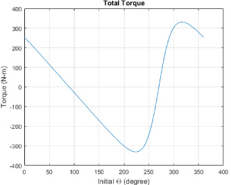
The produced torque per length is calculated versus two parameters: the initial reference angle at the end of the shaft with respect to the current angle and the distance from the end. As shown in Fig. 4, the produced torque per length is sensitive to the initial reference angle and distance from the end. The output torque is the integral of the produced torque per length along the rotor. The output torque versus initial reference angle at the end of the shaft is presented in Fig. 5. As it was predictable, the output torque is very sensitive to the initial reference angle and it changes periodically between the maximum torque and minimum torque. The minimum torque is negative and has the same magnitude as the maximum torque. According to Fig. 5, the maximum produced torque is obtained when the initial reference angle at the end of the shaft is −43.5669 degrees which is the best operating point. The maximum torque is 330.9 [N.m] while it becomes 387.44 [N.m] using the traditional qd0 model in which the STE is not considered (as ((27)) and ((28)) in which ∅
x
results −0.4036 degrees to obtain the maximum torque) or FEM without considering STE. It means the STE causes decreasing the output torque about 14.6%.
Since the finite element method (FEM) simulations are time-consuming, it is used for one initial reference angle that is identified by the proposed model. Therefore, one motor with length equal to length of one segment in proposed model is simulated for times equal to number of segments in proposed model (101 times). At the first simulation, current phase angle and rotor position applied in simulation is equal to the best working point base on proposed model results. The simulation is executed and the produced torque is obtained. Then the twisting calculated as it explained at the first paragraph of Section 4. Then the next position of rotor will be obtained (including twisting) and used for next segment simulation. For the next simulation the produce torque is added to previous transmitted torque to find the current transmitted torque. These steps are done repeatedly while the number of simulations be equal to number of segments on proposed model.

The produced torque per length versus initial reference angle at the end of the shaft and distance from the end.
Output torque versus initial reference angle.
The produced torque per length along the rotor calculated by proposed model and FEM simulation are shown in Fig. 6. As it seems in Fig. 6 the results of proposed model and FEM are very similar and the maximum produced torque per length is almost identical in these two resulted curves. The maximum produced torque per length is 193.72 [N.m] which is equal to the maximum produced torque per length using a conventional model. This maximum torque is obtained only at one point along the rotor and the produced torque on the other points is lower than that. The differences between the maximum torque per length and produced torque at other points are a function of the rotor position differences with respect to the point with the maximum torque. The rotor position difference is equal to twisting angle difference. The shaft twisting angle relates to the transmitted torque, as mentioned before. The transmitted torque and the twisting angle are calculated in simulations (proposed model and FEM) and presented in Fig. 7 and Fig. 8 respectively.

Produced torque per length unit versus distance from the end of the shaft.

Transmitted torque versus distance from the end of the shaft.
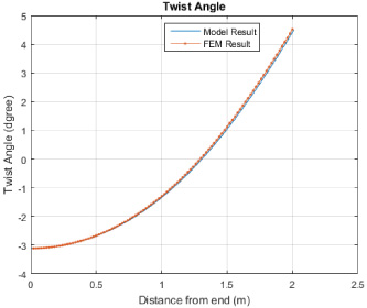
Twist angle versus distance from the end of the shaft.
The total shaft twist angle is about 7.6 degrees that is equal to 106.4 electrical degrees. This twist angle is small mechanically; by contrast, the electrical angle is very large. The effect of this twist angle on the output torque is about 14.6% base on simulation results.
The shaft twisting phenomenon occurs when the torque is transmitted along the shaft. The magnitude of the shaft twisting depends on the diameter, length, and stiffness of the shaft and also the magnitude of transmitted torque. To investigate the STE on the electric motor performance, a model which considers the twisting on electrical torque is required. In this article, a new differential form qd0 model is proposed to study the STE on an FSPM motor. The results of the proposed model are very similar to FEM results.
Base on the simulation results, the STE causes non-uniform distribution of torque along the shaft and the reduction of total output torque (for the case study obtained about 15%). In addition, the STE can perturb motor control system, due to rotor position variation along the shaft. On the other word, angular sensors of the motor control system sense position only at one point. Therefore the output of the sensor may not be suitable for the control system and some modifications are required for traditional control systems.