
Abstract
The aim of this work is the investigation of the simultaneous separation of magnetic (𝜇 r > 80) and conductive (σ ≈ 6 ×10⁷ S/m) particles in a designed magnetic separator. Such a separator consists mainly of a drum on which permanent magnets are arranged and a conveyor belt carrying the material to be purified. The separately driving of the drum and the conveyor belt allows the independent control of the frequency of the generated magnetic field and the displacement speed of the material to be treated. To generate high magnetic field, identical NdFeB permanent magnet bars with residual magnetic flux density B r = 1.2 T are used. To compute the particles trajectories, the magnetic field and the particle dynamic governing equations have been solved using the numerical finite element (FEM) and Runge Kutta (RK4) methods. The computing results have shown that the proposed separator permits the simultaneous separation of magnetic and conductive particles. To check the validity of the numerical results, experiments have been carried out on ferromagnetic powder and conductive particles of different sizes.
Introduction
Magnetic separation is a technique widely used in the processes of purification of liquids and gaseous materials and enrichment of ores [1–3]. It is based on the application of a magnetic field that acts selectively on the components of the treated material [4]. To extract a magnetic object from non-magnetic material one can efficiently use a static magnetic field. To separate conductive object from non-conductive material, a dynamic magnetic field is required [5]. In this last case, the separation is the result of the repulsive interaction between the eddy currents generated in the conductive object and the applied dynamic field. The eddy current separation has been widely studied and several separators have been carried out [6–9]. The applied field is generated by magnetized rotary cylinder and strong magnets [10,11]. The problems of eddy current separation based on permanent magnet drum reside mainly in the limited recovery of particles with diameter of less than 5 mm or those with poorly electrical conductivity [12,13]. Also, this kind of separators has a high cost because of the length of the magnets required for the treatment of materials of large quantities [14].
Among the main practical purposes of the study of magnetic separation problems are the improvement of the existing devices performances and the design of new prototypes. To increase the separation efficiency, a large number of magnets of small width may be used for small particles separation. Important improvement of the separation efficiency can be reached by the use of inclined magnet drum or special drums where the separation process takes place in two stages [14–16].
In this work, we present an analysis of the separation of conductive and magnetic objects from globally non-magnetic and non-conductive material in a designed separator intended for sorting and recovering metal waste resulting from an industrial process for manufacturing parts of agricultural vehicles. Such a separator consists mainly of a horizontal drum on which permanent magnets are mounted and a conveyor belt carrying the material to be treated (see Fig. 1). The drum and the belt are driven separately which facilitates the independent adjustment of the frequency of the generated magnetic field and the feed rate of the material to be treated.
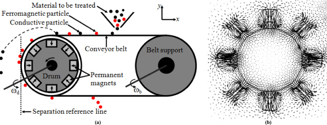
(a) 2D view of the designed drum separator. (b) 2D distribution of the generated magnetic field computed for a given time step and alternately oriented magnets.
In comparison to conventional application of the eddy current separation based on permanent magnet drum [14–16], the novelty of our work is that the permanent magnet drum is used for the simultaneous separation of conductive and magnetic particles of random geometrical shape and size from non-ferrous and non-conductive materials. In addition to the use of permanent magnet poles of small width permitting the generation of high gradient magnetic fields, an appropriate adjustment of the separation parameters permits the overcoming of the most problems and the increase of the separation efficiency.
The aim of our analysis is then the verification of the simultaneous separation of the conductive and magnetic particles and the investigation of the separation parameters on which the separation performances depend and the determination of the use limits of the separator.
To verify the separation of the cited kinds of particles, we have computed their trajectories. For this, we have solved the coupled magnetic and particle dynamic governing equations. Such a resolution has been done by using the coupled finite element (FEM) and fourth order Range Kutta (RK4) methods [17,18]. The geometrical invariance of the drum and the neglected effect of the magnetic particles magnetization and the induced current in the conductive particles on the applied field have permitted a two dimensional (2D) resolution. In such a resolution, the rotation of the drum has been taken into account. To determine the separation parameters (key factors) influencing the separation efficiency, we have considered particles of iron and aluminum of different size. For each case, we have studied the influence of the number of the magnets, the conveyor and the drum speeds. The obtained results show that for the used NdFeB permanent magnets (B r = 1.2 T), the designed separator permits a simultaneous separation of conductive (σ = 6 ×10⁷ S ⋅ m−1) and magnetic (𝜇 r = 80) particles. The separation efficiency depends on the number of magnets, the size of particles and the conveyor and the drum speeds.
To validate the computing results, experiments were carried out on iron and aluminum particles. In a first step, we have pointed out the dynamic nature of the generated field and the dependence between its frequency and the number of the magnets. To do such an investigation, we have measured and recorded the signal of the electromotive force induced in a coil placed on the drum during its rotation. In a second step, we have investigated the separation of conductive and ferromagnetic particles and determined the performances of the conceived separator. For NdFeB permanent magnets of B r = 1.2 T and size 12 × 10 × 100 mm3, the experiments have approved the simultaneous separation of the cited kinds of particles.
To estimate the separation efficiency, we have measured the distance between a reference point and the falling sites of the separated particles. The carried out measurements show that the separation efficiency depends on the number of magnets, the particle size and the conveyor and drum speeds. Concerning aluminum particles, we have treated plates of thickness of 1 mm and different surface dimensions. The critical size below which no separation occurs is 10 × 10 × 1 mm3. For ferromagnetic particles, we have treated iron powder constituted by ultrafine particles. The experiments have shown that the separation degrades with the increasing of the drum speed. Beyond a drum speed of 1800 rpm, the particles vibrate and remain stuck to the drum.
To compute the dynamic magnetic field required to separate magnetic and conductive particles and to take into account the effect of the induced currents related to the variation of the field and the displacement of the conductive particles we solved for each rotation step of the drum the equation given by:
Where,
The magnetic force applied on a magnetic particle is given by [19,20]:
Where,
The current density induced in the conductive particle related to the variation of the applied field is given by [21]:
The displacement of the particle in the applied field leads to the generation of an additional component of the induced currents given by [22]:
The resulting force applied on the conductive particle is given by [22]:
Where, m
p
is the particle mass and
In addition to the forces applied to the particles given by Eqs (2) and (5), we can mention the force of mechanical interaction of the particles with the conveyor belt and the magnetic dipole-dipole interaction between ferromagnetic particles. To solve the motion equation (6), we have only considered the magnetic, Lorentz and the gravity forces.
To justify the 2D resolution approach that permits the reduction of the computing time, we have made a comparison between 2D and 3D distributions of the magnetic flux density in the middle plane of the studied device. The results concerning the variation of the magnetic flux density along the length of two lines y
d
and x
d
situated respectively at x
0 = 5 mm and y
0 = 1 mm away from the perimeter of the drum are presented in Fig. 2. For a device depth d = 100 mm, the results show a negligible difference between the 2D and 3D values
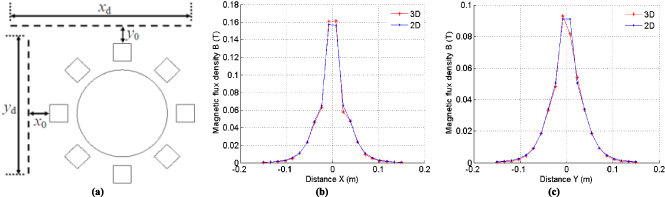
(a) The two computing lines. (b) Variations of the magnitude of flux density B along the length of the horizontal line (in the x direction). (c) Variations of the magnitude of flux density B along the length of the vertical line (in the y direction).
To show the dynamic nature of the generated field required to separate conductive particles, we have computed the flux density at a given point in the separation region related to a complete rotation lap of the drum. The obtained results for different number of identical permanent magnets of size 12 × 10 × 100 mm3 and B r = 1.2 T are shown in Fig. 3.
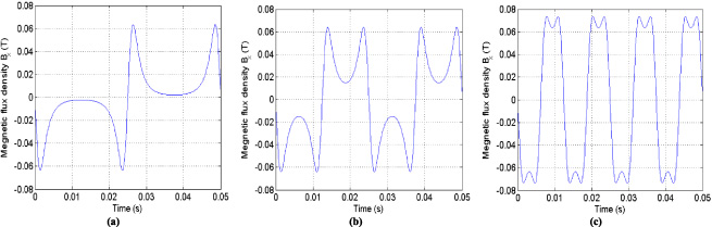
Variations of the magnetic flux density as a function of time for a complete rotation lap of the drum. (a) Case of two magnets. (b) Case of four magnets. (c) Case of eight magnets.
Figure 3 shows that the generated field is alternative and the frequency depends on the number of magnets (f = p. n d , n d is the drum rotation speed and p is the number of magnets pairs).
To show the separation possibility of the magnetic and conductive particles, we have computed and presented in Fig. 4 the resultant force applied on each kind of particle. On Fig. 4, we see that the force applied on a ferromagnetic particle is attractive which leads to its capture by the drum. The forces applied on diamagnetic and conductive particles are repulsive. These kinds of particles will be repulsed away from the drum. The force applied on a paramagnetic particle (𝜒 = 2.2 ×10⁻⁵) is attractive but with small magnitude in comparison to that applied on a ferromagnetic particle.
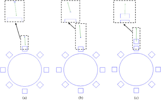
Resultant of the force applied on the considered particles. (a) Ferromagnetic particle (𝜇 r = 80). (b) Diamagnetic particle (𝜒 = −1 ×10⁻⁵). (c) Conductive particle (σ = 6 ×10⁷ S/m).
To verify the separation of the considered particles and to estimate the separation final position, we have computed and presented their trajectories. For a drum of four magnets with B r = 1.2 T and rotation speed n d = 3000 rpm, the results are presented in Fig. 5.
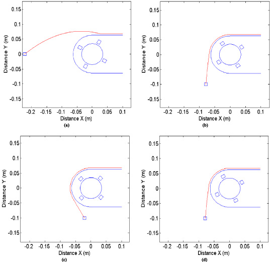
Obtained trajectories for particles size V p = 10 ×10 ×10 mm3. (a) Conductive particle, σ = 6 ×10⁷ S/m, 𝜌 = 2698 kgm−3. (b) Diamagnetic particle, 𝜒 = −1 ×10⁻⁵, 𝜌 = 8960 kg/m−3. (c) Ferromagnetic particle, 𝜇 r = 80, 𝜌 = 7860 kg/m3. (d) Paramagnetic particle, 𝜒 = 2.2 ×10⁻⁵, 𝜌 = 2698 kg ⋅ m−3.
Figure 5 shows clearly that for the used computing conditions, the ferromagnetic and conductive particles are successfully separated. The diamagnetic and paramagnetic particles have not been separated because of their very weak magnetic permeability. The separation of the last two kinds may be occurred for particles of very important sizes or for very high magnetic field.
To identify the parameters that can affect the separation efficiency defined here as the distance between the fall position of the separated particle and the reference line (see Fig. 1), we have firstly estimated the effect of the permanent magnets number and the drum rotation speed. For the physical properties of the particle that have led to the results of Fig. 5, the particle trajectories obtained for different number of magnets and drum rotation speed are shown in Fig. 6.
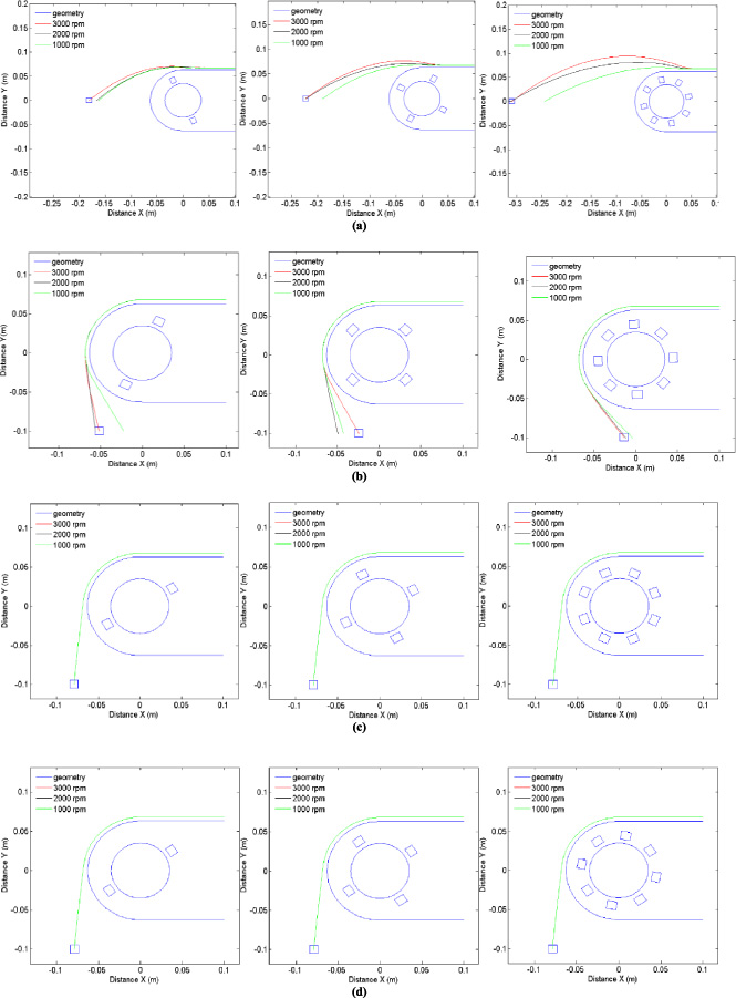
Variation of the particle trajectories as a function of the magnets number and drum rotation speed. (a) Conductive particles. (b) Ferromagnetic particles. (c) Paramagnetic particles, (d) Diamagnetic particles.
We have seen previously in Fig. 3 that the frequency of the magnetic field is a direct function of the number of magnets and drum rotation speed. For conductive particles, the origin of the magnetic force responsible to the separation is the induced currents that depend on the frequency. For that, we see clearly on Fig. 6.a that for a given number of magnets, the separation efficiency is a function of the drum rotation speed. The effect of the speed appears clearly on the vertical component of the force. On the other hand, the figure shows that for a given drum rotation speed, the multiplication of the number of magnets improve the separation efficiency.
To validate the computed results, to check the performances and to determine the limits of use of the designed separator, experiments were carried out thanks to a conception of a testing device (see Fig. 7). In the latter, the supply of the material to be treated is made at the left side of the belt. The movement of the latter allows its transport to the drum where the separation can occur. To allow an independent adjustment of the speeds of the belt and the drum, these objects are driven separately by two motors.
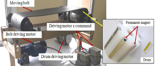
Realized testing device.
The carried out experiments were mainly devoted to point out the nature of the generated field (shape, amplitude and frequency), the simultaneous separation of conductive and ferromagnetic particles and the limits of use of the designed separator.
To check the nature of the field generated by the rotating drum, we have measured and recorded, by using of a digital oscilloscope, the evolution in time of the electromotive force E induced in a coil placed on the drum (the conveyor belt is at rest). The used testing device is shown in Fig. 8.
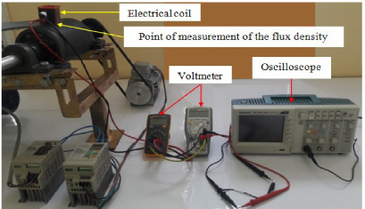
Realized device and measuring conditions.
As the coil is coreless, E has a linear function of B and hence it has the same form (E = 2.22Nf B S where, N is the number of the coil turns, f is the frequency and S is the cross section of the coil).
The comparison between the computed and measured electromotive forces obtained for the case of a drum with eight magnets and drum rotation speed n d = 3000 rpm is presented in Fig. 9.
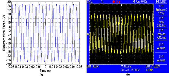
Comparison between the computed and measured electromotive forces obtained for a drum with eight magnets and a rotation speed n d = 3000 rpm. (a) Computed results. (b) Measured results.
From Fig. 9, we see that the computation and measurement give the same frequency f = 200 Hz. The measured (using the teslameter with hall effect probe) and computed values of the vertical component of the magnetic flux density at the measuring point (see Fig. 8) are respectively B y = 0.029 T and B y = 0.031 T. The relative error is ΔB y ∕B y = 6. 4% which shows a good agreement between the computation and the measurement. To show the effect of the number of permanent magnets on the frequency of the magnetic field, we present in Fig. 10 the comparison between the computed and measured electromotive force obtained for a drum with four magnets rotating at the same speed n d = 3000 rpm. For this case the frequency is f = 100 Hz, it is reduced to half the value related to the case of eight magnets.

Comparison between the computed and measured electromotive forces obtained for a drum with four magnets and a rotation speed n d = 3000 rpm. (a) Computed results. (b) Measured results.
Let study the effect of the drum rotation speeds on the frequency of the magnetic applied field. For a drum with four magnets and for two different speeds 1800 rpm and 2400 rpm, we give in Fig. 11 the comparison between the computed and measured variations of the electromotive force as a function of time.
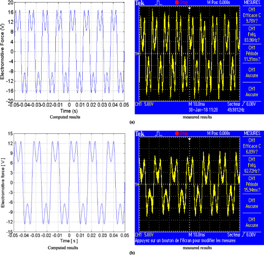
Comparison between the computed and measured electromotive forces obtained for a drum with four magnets. (a) n d = 2400 rpm. (b) n d = 1800 rpm.
The results of the first series of experiments have permitted a practical verification of the sinusoidal nature of the generated field and the effect of the number of magnets and the drum speeds on the field frequency. We have seen that the increasing of the number of magnets or the drum rotation speed leads to the increasing of the field frequency. This finding means that the number of magnets and rotation speed are key factors for the improvement of the separation efficiency of conductive particles because the magnetic force responsible of separation is a function of the frequency.
In this section, we present an experimental verification that concerns the separation efficiency and limits of use of the designed separator. To determine the separation efficiency, we have measured the distance between the fall position of the separated particle and the reference line using a graduated ruler (see Fig. 12).
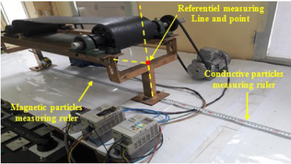
Referential point for measuring the separation distance.
Concerning the separation of ferromagnetic materials, we have treated iron powder and particles of different sizes and forms (see Fig. 13).
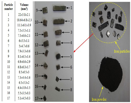
Treated ferromagnetic material.
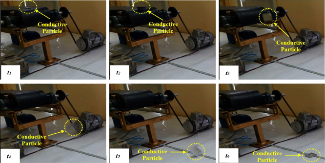
For the case of iron powder (ultrafine particles) we have firstly verified the separation efficiency for the case of a drum with four magnets and a belt moving speed v = 0.47 m/s. Some recorded sequences of the separation process are presented in Fig. 14.
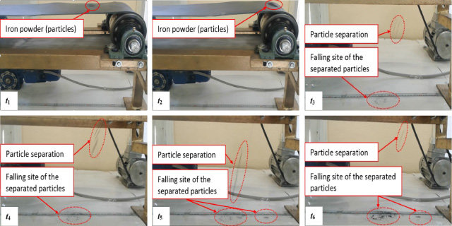
Some recorded sequences of the separation process of iron powder obtained for a drum with four magnets, belt moving speed v = 0.47 m/s and the drum is in rest.
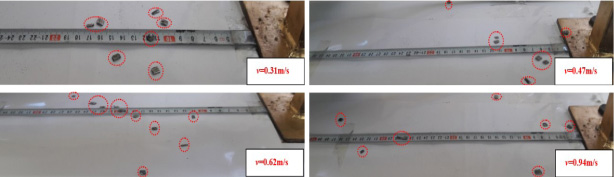
The sequence related to the instant t 6 shows that all the powder fell behind the reference point, which means that a successful separation has been obtained. To estimate the effect of the belt speed on the separation efficiency we have observed and recorded the separation process for different belt moving speeds. The positions of the separated particles related to the treated cases of belt speed are shown in Fig. 15. The figure shows that the best separation efficiency is obtained for v = 0.62 m/s. Beyond this value, the separation efficiency starts to degrade. For a belt speed of v = 1.57 m/s, a low efficiency is obtained, a part of the powder fell before the reference point and the other part remains stuck to the drum.

Sites of the separated particles obtained for a drum with four magnets and different conveyor belt speeds.
To estimate the effect of the size of the particles on the separation efficiency, some particles of significant size have been treated (see Fig. 13). For the same operating conditions, a drum with four magnets and a belt speed v = 0.47 m/s we have obtained the results of Fig. 16.

Some sequences of the recorded separation process of particles of significant size average 5 × 5 × 3 mm3 obtained for a drum with four magnets and belt moving speed v = 0.47 m/s.
Figure 16 shows that for the treated quantity of particles and for a belt speed v = 0.47 m/s, some particles have been separated but two particles remain stuck to the drum like that is obtained for the case of v = 0.31 m/s. Beyond a speed v = 0.62 m/s all the particles have been successfully separated and fell behind the reference line (see Fig. 17). For the particles of higher size, we have obtained the same observations. The rising of the belt speed has considerably improved the separation efficiency. Beyond a speed v = 0.62 m/s all the particles have been completely separated. Concerning the effect of the particle size on the separation efficiency, only a qualitative estimation has been presented here because of the ultrafine size of the particles constituting the iron powder that did not be measured. Such estimation was based on the pictures of some recorded separation sequences.
Sites of the separated particles of significant size obtained for a drum with four magnets and different conveyor belt speeds.
To show the effect of the drum rotation speed on the separation efficiency of particles of higher sizes several cases of drum speed have been studied (600 rpm < n d < 1800 rpm). The recording of the separation process has shown that a complete separation is obtained for all the treated speeds. The effect of the increasing of the drum speed leads to a falling of the particles near the reference line.
The qualitative comparison between the theoretically and experimentally obtained results shows good agreement. The same phenomena and the same nature of interdependence between the separation efficiency and the considered separation parameters have been obtained. The slight difference is largely due to the 2D calculation approach and the approximation of the really non-regular geometries of the particles by regular geometries in the calculations.
To verify the capability of the designed separator to separate conductive materials we have treated the case of conductive particles that are pieces of thickness of 1 mm and different surfaces (see Fig. 18).
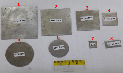
Treated conductive pieces.
The dimensions of the treated conductive pieces are illustrated in Table 1.
Dimension of the treated conductive pieces
In order to exclude the effect of the centrifugal force related to the motion of the conveyor belt on the separation (case of high speeds), a low belt moving speed v = 0.47 m/s is firstly considered. For a drum with four magnets, the recording of the separation of aluminum piece of size 50 × 50 × 1 mm3 has given the sequences presented in Fig. 19.
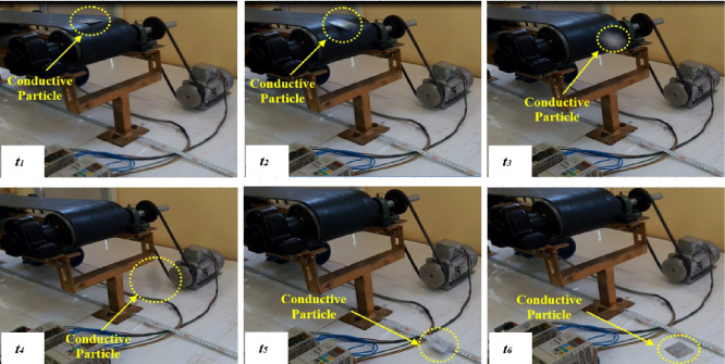
Separation sequences of a square conductive piece number 1 obtained for a four magnets drum, rotation speed n d = 1800 rpm and belt moving speed v = 0.47 m/s.
The last sequence of Fig. 19 shows that the separation distance of the piece is 23 cm (distance between the center of the piece and the reference point). The separation distances obtained for the pieces of Fig. 18 are shown in Table 2.
Separation distance of the treated conductive pieces
To estimate the effect of the drum rotation speed, we have measured the separation distance for the pieces presented in Fig. 18. The increasing of the rotation speed has led to the results of Table 3. This table shows that the increasing of the rotation speed improves the separation distance. From the results of Table 3, we see that the separation efficiency increases with the increasing of the particle size. For better clarity we present graphically in Fig. 20 the variation of the separation distance as a function of the particle size related to a drum speed of 3000 rpm (see Table 3).
Separation distance as a function of the drum rotation speed
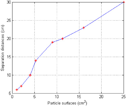
Variation of separation distances of conductive particles as a function of the particle sizes for a drum speed of 3000 rpm.
To estimate the effect of the magnets number on the separation efficiency, we have recorded the separation process and measured the separation distance for piece number 1 for the case of eight magnets drum. The recorded separation sequences are presented in Fig. 21.
Separation sequences of a square conductive piece number 1 obtained for an eight magnets drum, rotation speed n d = 1800 rpm and belt moving speed v = 0.47 m/s.
The last sequence in Fig. 21 shows that the separation distance of the piece is 35 cm (distance between the center of the piece and the reference point). In comparison with the case of a drum with four magnets, we see that the final position of separation depends on the magnets number.
The experimentally obtained results validate qualitatively the achieved theoretical study because the same phenomena have been observed. The quantitative difference between the computed and measured results resides in the particles distance of separation, because the 2D modeling of magnetodynamic study.
To verify the capability of the designed separator to separate diamagnetic materials we have treated copper pieces [24]. To generate a magnetic force instead of the Lorentz force, a static magnetic field was used. The treated pieces are shown in Fig. 22.

Treated diamagnetic copper pieces.
The recording of the separation process for the case of the piece number 1, a drum with four magnets and conveyer belt speed v = 1.25 m/s has given the results of Fig. 23.
Figure 23 shows that the piece has been ejected away from the reference line. The ejection distance is 16 cm. To verify the real cause of the piece ejection, we have reduced the belt speed to v = 0.62 m/s. The recording of the separation sequence has shown that the pieces fall positions is closely near the reference point. This leads to the fact that the previous separation is caused by the centrifugal force not due to the magnetic force. The increasing of the size of the piece has led to the same results. These results show that the designed separator does not permit the separation of diamagnetic material.
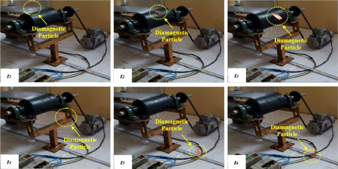
Separation sequences of a square diamagnetic piece of dimension 0.1 × 3 × 3 cm3 obtained for a four magnets drum and belt moving speed v = 1.25 m/s.
Since paramagnetic materials have almost the same absolute magnetic permeability as diamagnetic materials, the separator also will not allow the separation of paramagnetic materials.
For this type of particles, a good qualitative agreement between theoretically and experimentally results are obtained. For the considered operating parameters of the proposed separator para and diamagnetic particle can’t be separated.
In the achieved work, the simultaneous separation of non-homogeneous metallic materials (particles and pieces) in a permanent magnet drum separator has been theoretically and experimentally investigated. The theoretical study has been based on the computation and the analysis of the behavior of the particles and pieces. The 2D resolution of the separation problem is justified by the neglected effect of the device ends. This fact has been experimentally verified. The analysis of the particle trajectories has shown that a simultaneous separation of the considered materials can be realized. Also, the analysis has shown that the separation efficiency depends strongly on the magnets residual flux density, the size of the particles, the magnets number, the drum rotation speed and the conveyor belt moving speed. The achieved experiments have shown good qualitative agreement between theoretical and experimental results. The same phenomena and nature of dependence between the separation efficiency and the separation parameters have been obtained for all the treated types of particles. The distinguished differences between theoretical and experimental results are due to the 2D calculation approach, the approximation of the really non-regular geometries of the particles by regular geometries and the neglecting of the frictional forces and the magnetic interaction between ferromagnetic particles.
Finally, we conclude that the proposed separator allows the simultaneous separation of conductive and ferromagnetic particles of fine size. For conductive particles, the separation efficiency has strong dependence on the particle size. The perspective of this work is a 3D modeling and optimization of the separator to improve its performances and to allow the separation of para and diamagnetic particles.
Footnotes
Acknowledgements
This work was supported by the General Direction for Scientific Research and Technological Development, Algeria, within the Research Inductics Network.