
Abstract
Permanent magnets need to be magnetized with a high magnetic field for retaining their maximum polarization. If the magnetizing field is not sufficiently high, the permanent magnet will not reach its maximum energy product. Additionally, the magnet easily suffers demagnetization because the remanence and coercive field will drop in highly non-linear characteristic. This paper presents an approach which models the local magnetization of permanent magnets during and after impulse magnetization. Common hysteresis models are not capable of modelling the impact of virgin magnetization on demagnetization behavior of permanent magnets. Therefore, measurements suit as interpolation basis for the finite element method.
Introduction
High energy rare-earth magnets are nowadays applied to many applications ranging from electro-mechanical devices to sensors [1]. The virgin material magnetization requires the application of magnetic fields up to several kA/m. To achieve sufficient fields in the magnetizing coils currents in range of several hundreds of kA are produced by pulse magnetizers [2].
The magnetization process is the key point for obtaining fully charged high performance magnets: non-uniform patterns could lead to failures in the worst cases. It is therefore crucial to dispose of numerical tools [3] and measuring devices [4] capable of correctly assessing the physical properties of the permanent magnet subjected to a magnetization process. Some authors have adopted the classical Preisach [5] or Jiles-Atherton [6] hysteresis model to predict the behavior of hard magnetic materials: these approaches generally works for fully (pre-)magnetized samples, while the interdependency of the virgin magnetization process and the demagnetization is still challenging. In this paper, we propose a FEM based simulation scheme that rely on interpolations of virgin-field dependent demagnetization curves. This scheme is suitable for evaluating the local magnetic flux density in all the points of the permanent magnet once the geometry and the current pulses are known.
Modelling permanent magnet magnetization in finite element method
Modelling magnetic material in finite element analysis is a complex problem, due to non-linearity and history dependency are numerically challenging. Equation (1) reveals the partial differential equation, derived by the Maxwell equations for low frequency case, based on the magnetic vector potential
Permanent magnet magnetization is not only dependent on the present magnetic field but also highly non-linear depending on the peak of magnetic field during the magnetization process [7]. In Fig. 1. the magnetization
Magnetization (in easy direction) as function of the magnetic flux density and the magnetizing field (in same direction). The curve corresponding to 
Paper [1] discusses the impulse magnetization of sintered Nd-Fe-B magnets for cylindrical samples of 20 mm height and 35 mm radius. The magnetizing fixture is a cylindrical coil with an inner/outer radius of 80/150 mm and 193 mm height, see Fig. 2. The material grade is N38 with a remanence of Br
Test case geometry of cylindrical pulse magnetizer. The geometry corresponds to [1].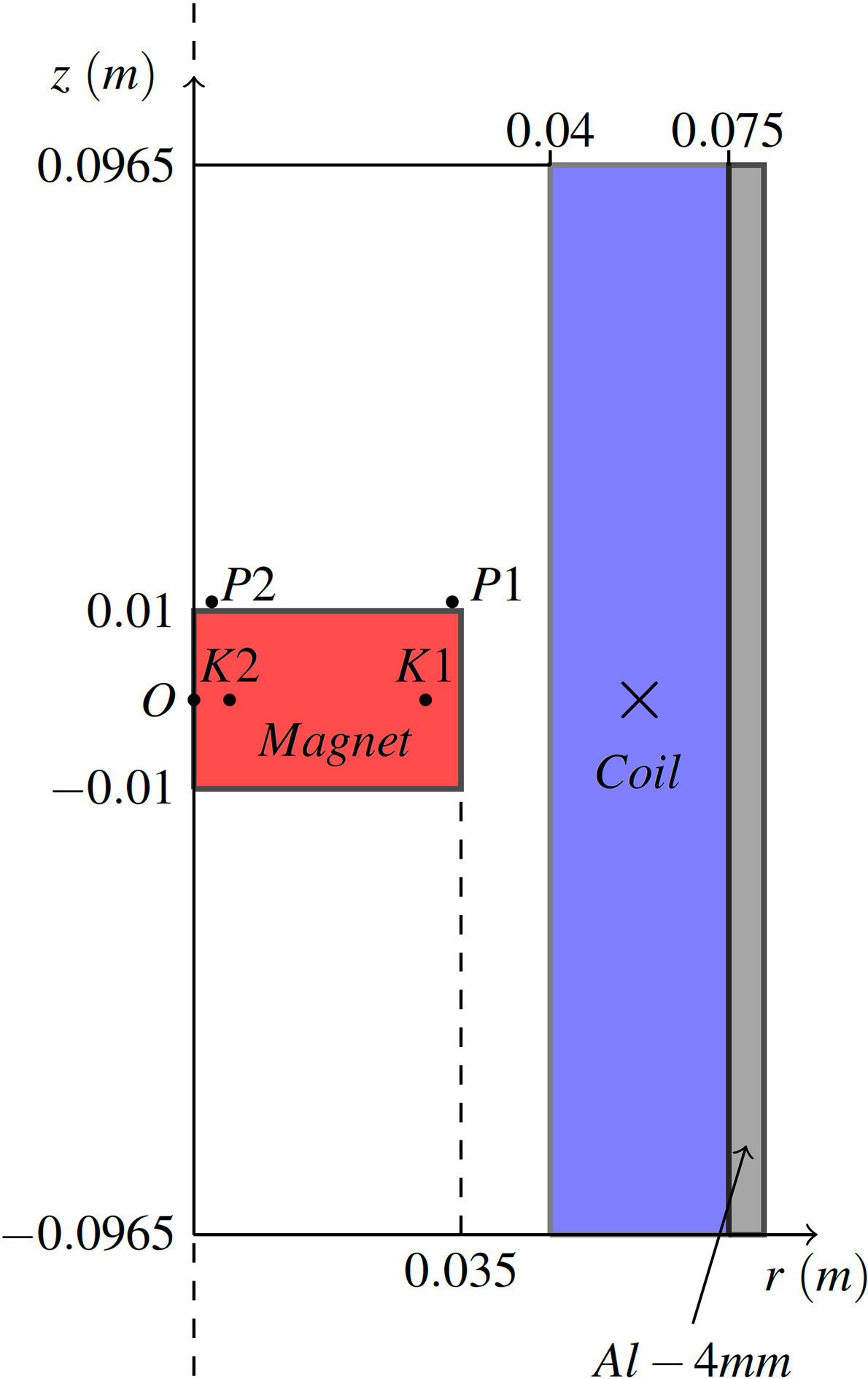
Current pulse at the maximum voltage. The data retrieved from [1].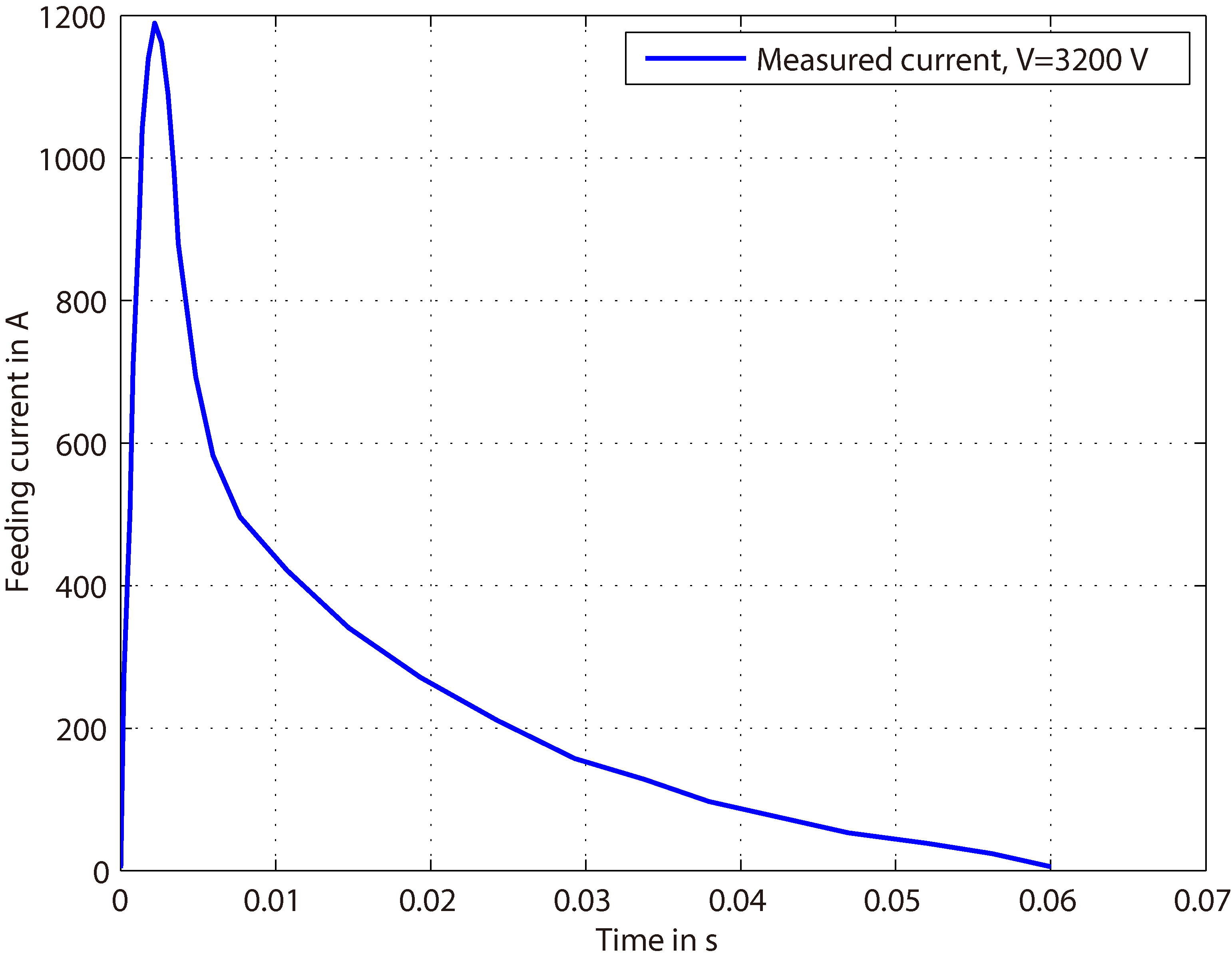
Arrow plot: magnetic flux density vector plot in T. Color map: stored magnetizing magnetic field in A/m (scalar).
Magnetic flux density at the end of the current pulse. Contour lines: iso A

BH plane of points K1 and K2 at V 
Assuming the coil inductance and resistance to be independent on the current value, the current pulse in Fig. 3 is scaled linearly with the magnetizer voltage to excite the current driven simulation. The current peak of 1200 A occurs at 2.6 ms and corresponds to the change between virgin magnetization loop and the demagnetization as a function of the peak magnetic field strength and present magnetic flux density. The slope of the impulse current curve is crucial for the resulting eddy currents. Especially the sloping behavior after the peak current causes local demagnetization.
Figure 4 illustrates the distribution of magnetic flux density and magnetic field strength at the peak of the current pulse (t
Figure 5 illustrates the distribution of magnetic flux density at the end of the current pulse (t
In Fig. 6 the comparison between the results of the proposed FEM and the measurements retrieved by [1] of the magnetic flux density at points P1 and P2 of Fig. 2 is demonstrated. The measurements show a local magnetization reversal in the middle of the sample. Although the magnetizing field continuously increases with the voltage, at low voltages, the demagnetizing field caused by eddy currents magnetize the sample in the opposite direction. Despite of slight quantitative deviations the simulation methodology is qualitative in good agreement with the measurements.
In Fig. 7 the BH plane of points K1 and K2 inside the permanent magnet at V
The above approach is also suitable for the study of the in-situ magnetization process of permanent magnet machine rotors. This subject has been dealt with in literature over the past few years [8, 9, 10, 11, 12], but often considerable simplifications have been made. A similar approach to the one presented here is also used in [8, 9] for the magnetization of surface magnets. Interior mounted magnets are studied in [10, 11] with a magnetic circuit models compared to FEM.
Test case geometry of pulse magnetizer for spoke-type pm rotors.
Magnetic flux density at the end of current pulse. Contour lines: iso Az lines. Color map: magnetic flux density in T (scalar). Arrow plot: magnetic flux density vector plot.
BH plane of points A1, A2 and A3.
In Fig. 8 an example geometry of a spoke type permanent magnet rotor is presented. Due to symmetry, the simulation is only carried out on one of the four rotor poles. The material behavior and the shape of the current pulse are kept. However, the maximum amplitude of the pulse is raised more than 16 times for the 10-turn conductor of 20 mm copper wire to achieve sufficient saturation. In contrast to the simulation in section three, the particularly special is the silicon iron, which is assumed to be non-conductive.
During the magnetization process, the magnetic flux first flows over the front and rear soft magnetic SiFe bride until they are saturated, before it crosses the permanent magnet. Because only one external magnetizing coil is energized, an inhomogeneous field is created which decreases in the magnet from the outer to the inner radius of the rotor. A second inner magnetization coil energized in the opposing direction can help to homogenize the field.
In Fig. 9 the magnetic flux density at the end of the current pulse is depicted. The remanent magnetization of the permanent magnet fully saturates the silicon iron bridges. The magnetic load line of the magnetic circuit highly demagnetizes the permanent magnet. Due to the inhomogeneous magnetization, the center of magnetization is somewhat more towards the outer edge of the magnet.
In Fig. 10 the BH plane of points P1, P2 and P3, derived by the non-linear and magnetization-history-dependent model presented in chapter 2, is exhibited. The drop of the magnetization from the outer to the inner side of the rotor (P3-1-2) can be clearly seen. Not only that the points suffer from different load lines, they have also all seen a different magnetizing field strength and therefore run on separated demagnetization lines.
An approach for modelling the local demagnetization of permanent magnets after virgin magnetization has been presented. The methodology is based on the history dependent interpolation of material magnetization characteristic. A material class is added to COMSOL to be utilized in transient two-dimensional simulations in cylindrical and cartesian coordinates. The methodology is validated on measurements of virgin magnets magnetized in an impulse magnetization coil [1]. The impact of local demagnetization with respect to eddy currents raised by magnetization impulse is discussed in detail. Furthermore, this technique is applied to more complex magnetizing equipment, such as multipolar magnetizers for electric machine rotors. The example geometry already illustrates some of the problems arising from the silicon iron magnetic circuit. Together with a field circuit coupling, the method offers a great potential for the optimization of pulse magnetizers, with respect to local demagnetization caused by eddy currents. The transient effects must not be ignored when designing an impulse magnetizer.