
Abstract
This paper presents a summary of a vibrational behaviour investigation of a 27 slots/24 poles combination surface mounted synchronous electric motor. To achieve this investigation, first, an electromagnetic analysis is done using a quasi 3D finite element model allowing to consider the rotor skewing and to compute the machine magnetic quantities. Second, a modal analysis is done using a 3D FE structural model in order to compute the motor natural frequencies for two cases of contact (Prefect and Adjusted), which are correlated with the magnetic pressure harmonics to extract the possibly excited modes and to show the contact coefficients influence on the overall results. Third, a structural mechanical analysis under static magnetic loads is done, in which the vibrational response for each harmonic of the magnetic pressure is computed in order to determine which harmonic is responsible of high order displacements. Finally, a structural mechanical analysis under time varying magnetic loads is done to compute machine’s vibrational response for a chosen operating speed using the corresponding local magnetic forces distribution.
Introduction
Nowadays, noise and vibrations are considered as critical aspects in the integration of electrical machines in embarked applications such as automotive and aeronautics. This makes that analysing their vibrational behavior in the early stages of the design process an important issue. Noise and vibrations of electromagnetic origins constitute important drawbacks that can be reduced whether by stiffening the machine or by controlling electromagnetic forces. The generation of noise in rotating machines is particularly due to the poles and slots combinations which impact directly and strongly the harmonic content of the magnetic induction [1, 2]. A bad combination is responsible for strong vibrations and significant noise. This paper presents a full vibrational investigation approach of a 27 slots/24 poles combination surface mounted synchronous electric motor.
Electromagnetic analysis
Presentation of the studied motor
The electromagnetic performances of the studied machine are computed using a quasi 3D FE model, with which the magnetic pressure and the local magnetic forces are computed. This choice is justified by the fact that those output parameters depend highly on the 3D shape of the structure and also in order to take into account the rotor skewing. Figure 1 presents the machine geometry and Table 1 gives its main parameters.
SMPM motor main parameters
SMPM motor main parameters
SMPM motor geometry and winding distribution.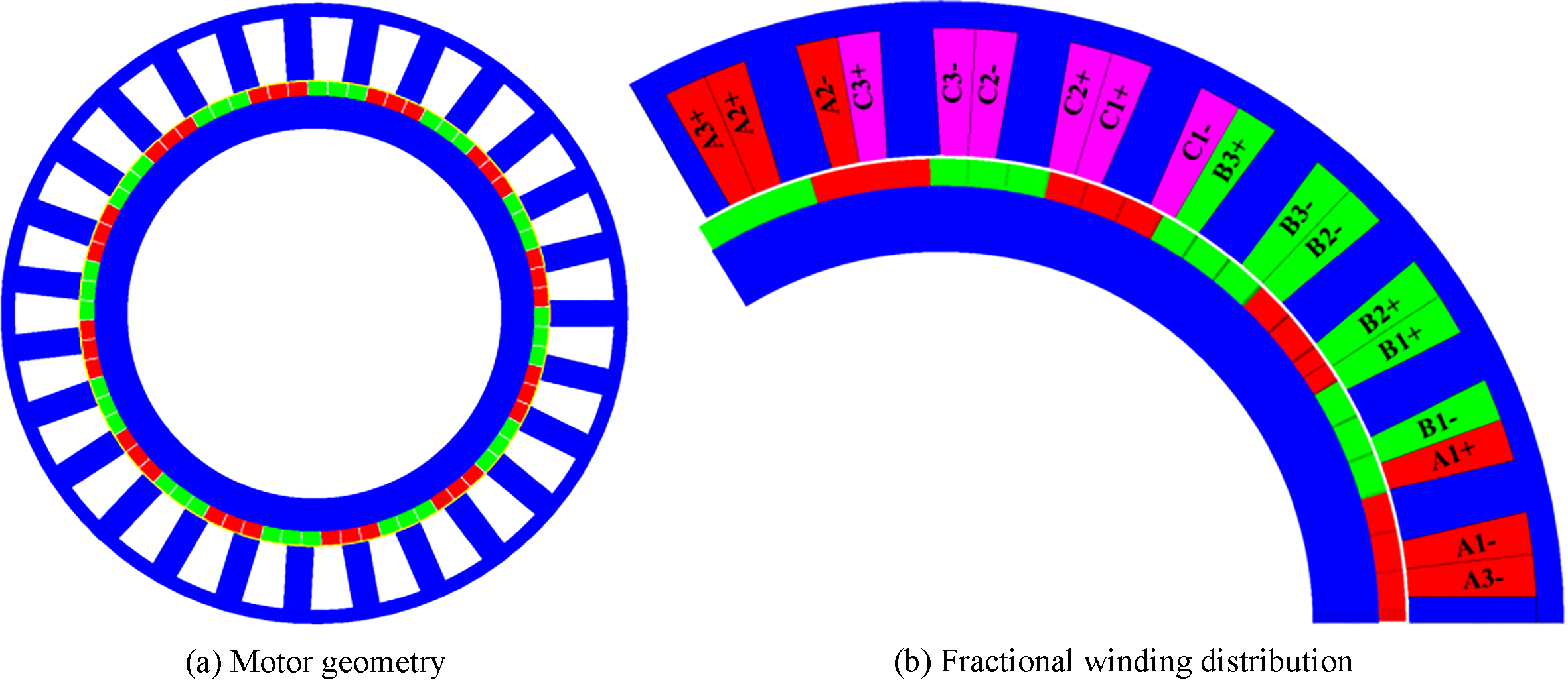
In order to build the electromagnetic model, a ferromagnetic axially laminated steel (M350_50A) is used for the stator and rotor core magnetic circuit modelling. While, the magnets are modelled as Neodymium-Iron-Boron (NdFeB) with a relative permeability of 1.04 and a remanent field of 1.22 (T). Once the model is built, the global and local electromagnetic quantities are computed. The cogging torque reduction is illustrated in Fig. 2 using rotor skewing technique. Figure 3 gives the electromagnetic torque and its harmonics while, Fig. 2 illustrates air gap flux density. Figure 4 gives the local distribution of the magnetic pressure and its harmonics.
Cogging torque with and without rotor skewing and on load airgap magnetic flux density.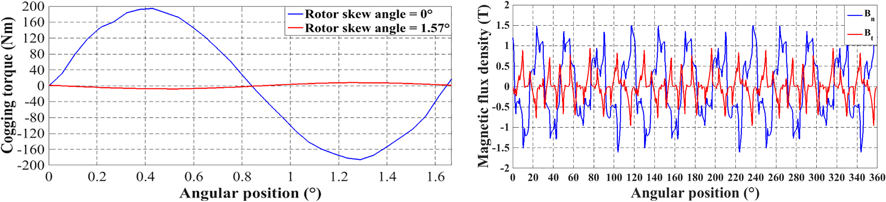
Electromagnetic torque and its harmonics.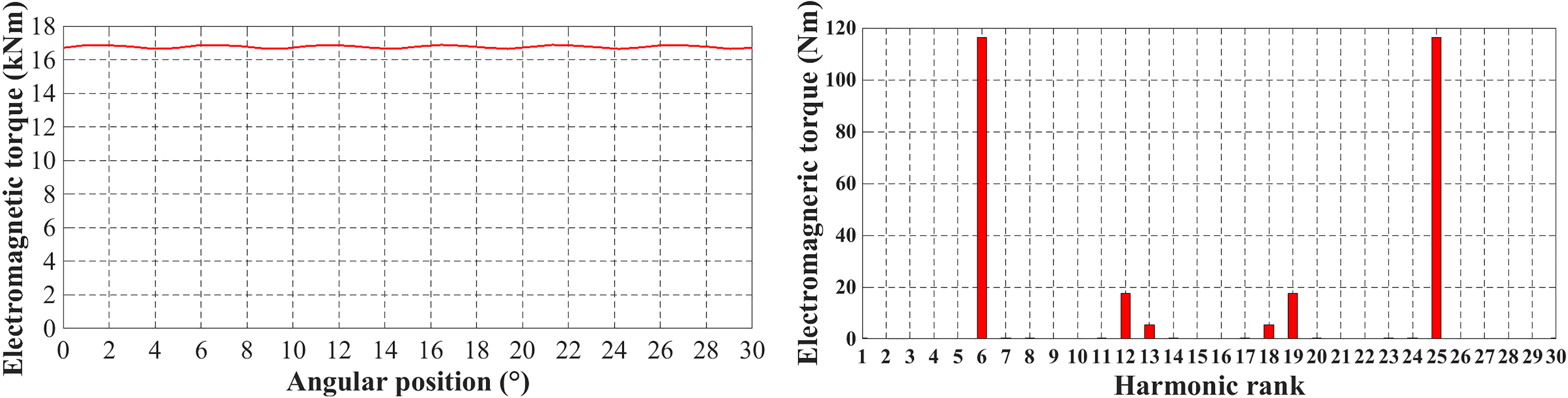
Magnetic pressure on the stator core inner radius and its harmonics.
Complexity of electrical machines mechanical modelling
Structural complexity of a real electrical machine makes it tedious to model with FEM down to the very last detail [6]. Usually, structure elements which have complex geometric shapes are approximated with simple shapes such as cylinders. In addition, materials can never be perfectly taken into account and mechanical coupling between bearings shields and the frame is difficult. In order to develop the proposed mechanical model, some assumptions were formulated [3]. The difficulty of a vibrational behaviour investigation comes then to the consideration of the different involved physical phenomena (Fig. 5) detailed below [5].
Complexity of electrical machines mechanical modelling.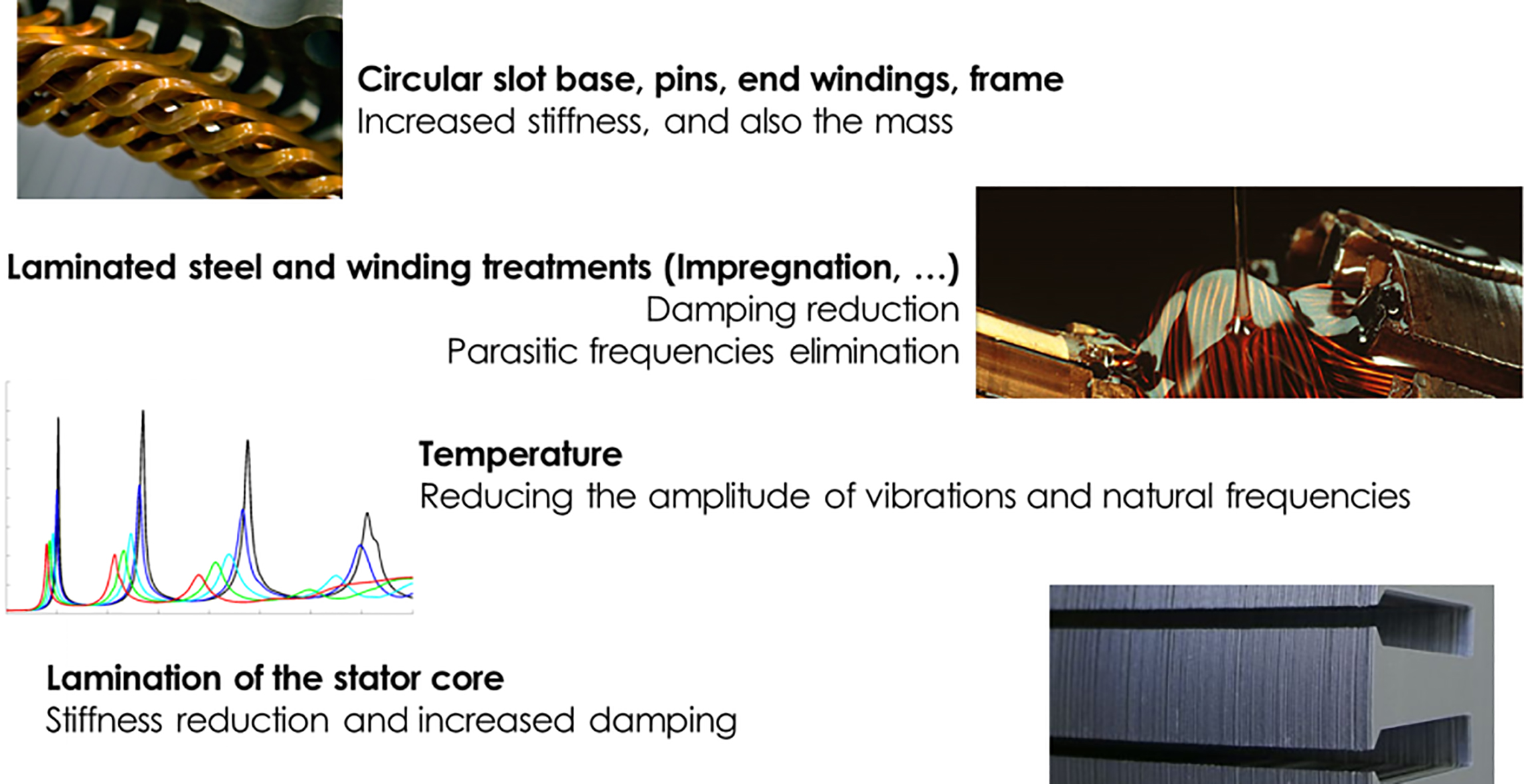
The vibrational behaviour investigation is restricted to the stator. Indeed, even if the rotor is subject to similar airgap magnetic forces than the stator but because of its shape and the rotational degree of freedom, the rotor is less affected by the electromagnetic force waveform. Also, knowing that the rotor have a smaller incident surface compared to the stator. All this makes that usually the rotor is not considered as a source of vibration and noise of electromagnetic origins.
Temperature influence
The vibrational behaviour is influenced by the stator temperature. This influence is very difficult to be modelled and quantified as it has a direct impact on the materials mechanical properties of insulations, conductors and the other materials. Generally, for the steel, the Young elasticity modulus is lower when the temperature rises. Contrarily, the Poisson ratio becomes higher with a rise of temperature. In our case the temperature influence is neglected and the FE calculations are done for an ambient constant temperature.
Winding and end-windings influence
The consideration of coils is done by changing the Young elasticity modulus associated to this part which is considered mechanically isotope.
Frame influence
Knowing that the crankcase count for about 10% of the total mass of the stator and has a length 1.6 times the stator ones; its influence cannot be neglected. In our case, in addition to the frame, the cooling circuit should also be considered as the frame is not directly in contact with the stator core.
Lamination influence
The lamination is used in order to reduce eddy currents but the elastic connection between each sheet makes it impossible to transfer the elastic forces between them. The vibration behaviour of the stator core is particularly influenced by the elastic parameters of the rolled sheet package. To take into account the influence of the lamination, orthotropic steel is considered to represent the lamination of the stator yoke in our case [4].
Contact coefficient and geometrical simplifications
Winding connection
Knowing the difficulty of the characterisation of windings mechanical properties which are highly depending on the manufacturing process and the fact that they have heterogeneous properties due to their composition. Consequently, modelling the winding requires a homogenisation method for the FE modelling. In addition to this difficulty, the existing knowledge on the contact conditions between the windings and the magnetic core is limited and or unknown. So in order to be as near as possible from the real vibrational behaviour of the studied machine some adjustments as proposed in literature [1] needs to be occurs, such as, separating the mesh of the contact faces between the magnetic core and the windings or acting on the contact coefficients.
Housing connection
When performing FE simulations, modelling the connections between the structure elements are necessary to recreate real settings, as they directly affect their stiffness. In FE the most obvious modelling is to associate both meshes and merge the contact nodes, representing then a perfect cohesion between the two pieces. However, some manufacturing processes do not guarantee an homogeneous cohesion over the entire contact surface. Therefore, these issues need to be studied in order to estimate the contact coefficient depending on the studied machine (Table 2).
Normal surface contact coefficients
Normal surface contact coefficients
Exploded view of the modelled structure elements after geometry simplification (1: end bell; 2: stator core; 3: frame & cooling circuit; 4: windings & end windings; 5: end bell).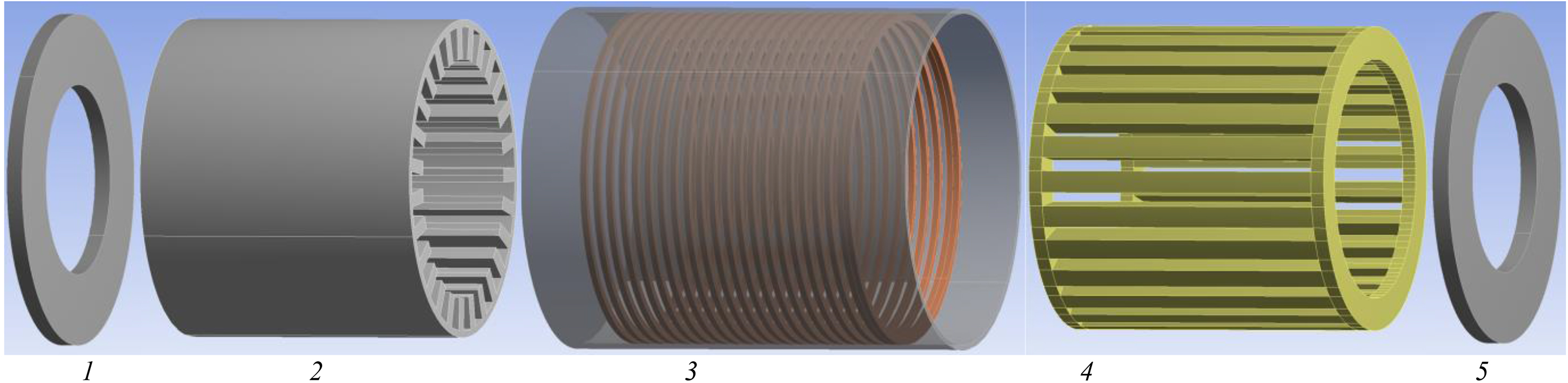
The on load vibration analysis is very time consuming due to the fact that the mesh in the stator core inner radius should be fine to allow a satisfactory magnetic force distribution on the stator teeth’s faces. So, for the mean reasons the structure geometry is simplified as illustrated in Fig. 6.
Fixation support
Usually the electrical motor support is considered stiff enough and in addition, the shape of the support required a fine mesh which is highly cost-effective, so for simplification issues the fixation is replaced by limit conditions on the frame at the exact locations with U (x, y, z)
Vibration analysis
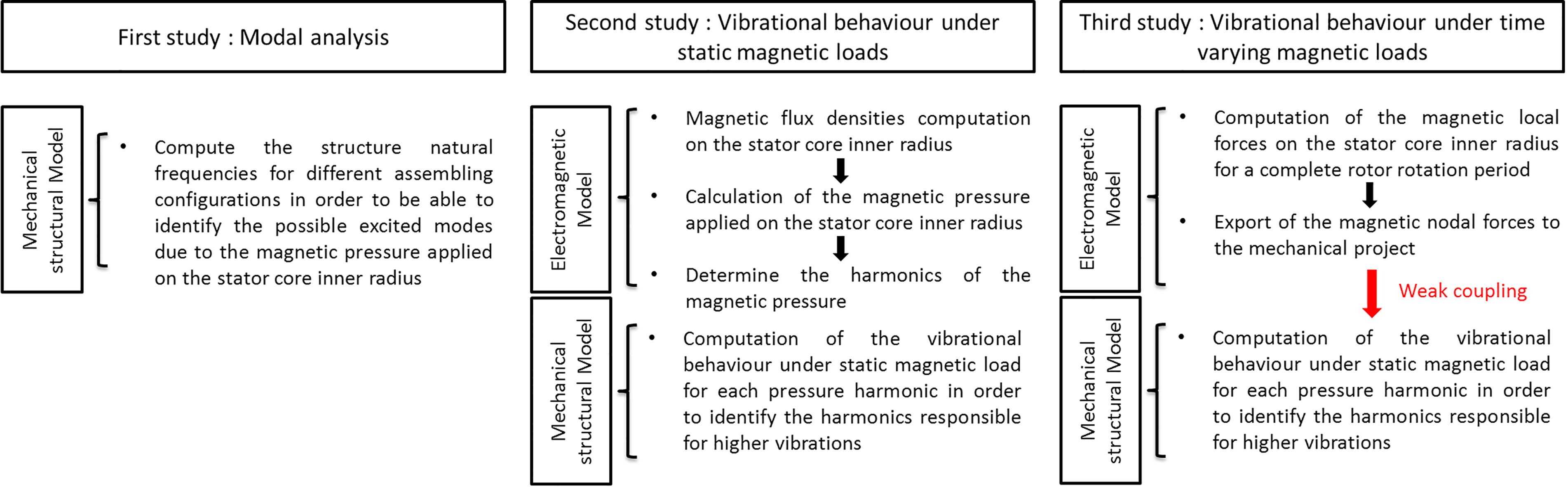
The diagram below details the main studies for the vibrational behavior investigation.
Modal analysis
In order to identify the harmonic ranks of magnetic pressure responsible for noise, a correlation between them and the natural stator’s frequencies is done. Figure 7 shows the influence and the importance of the contact coefficient on the natural frequencies a gap of approximately 100 Hz is noticed. Figure 8 gives the comparison of the overall natural frequencies of the stator core plus windings and end-windings plus the frame, one can note that the frequency gap increase from a mode to the other depending on the contact coefficients (perfect, or not), given in Table 2.
Illustration of the natural frequency gap in fuction of contact coeff.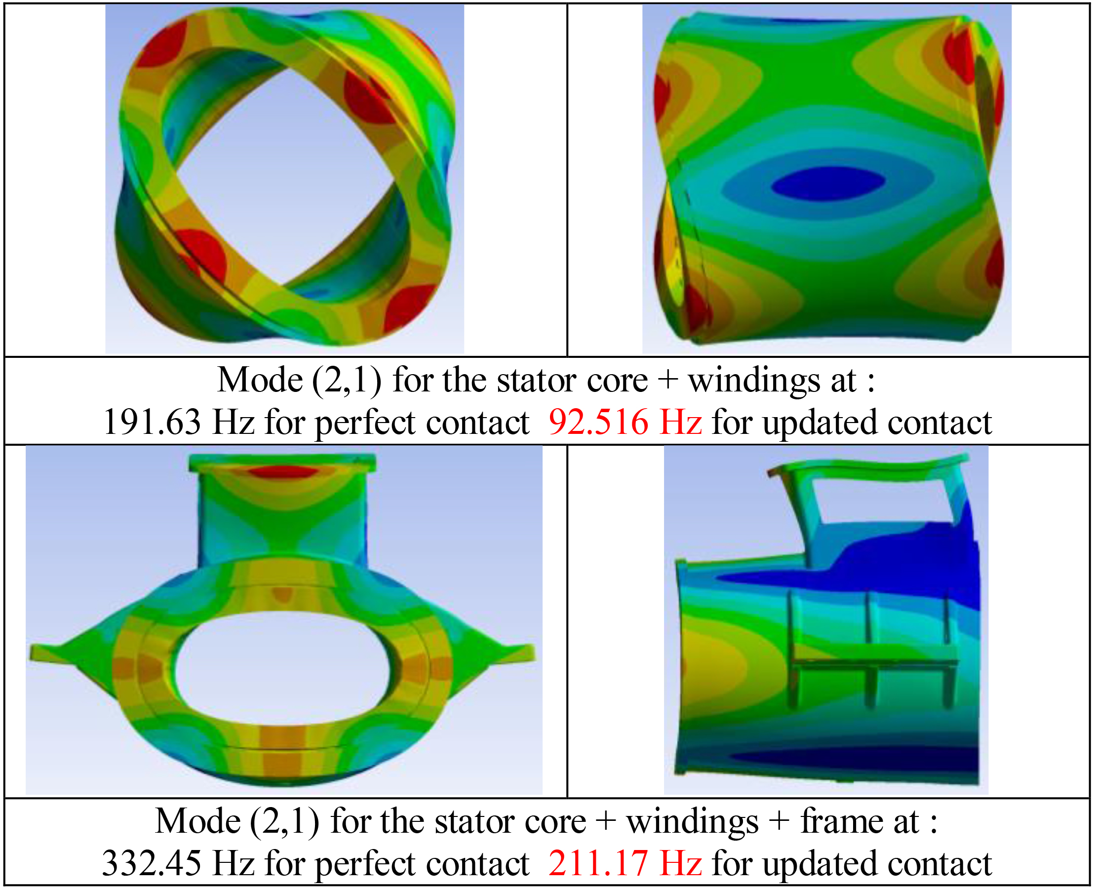
Influence of contact coefficions on natural frequencies (Hz).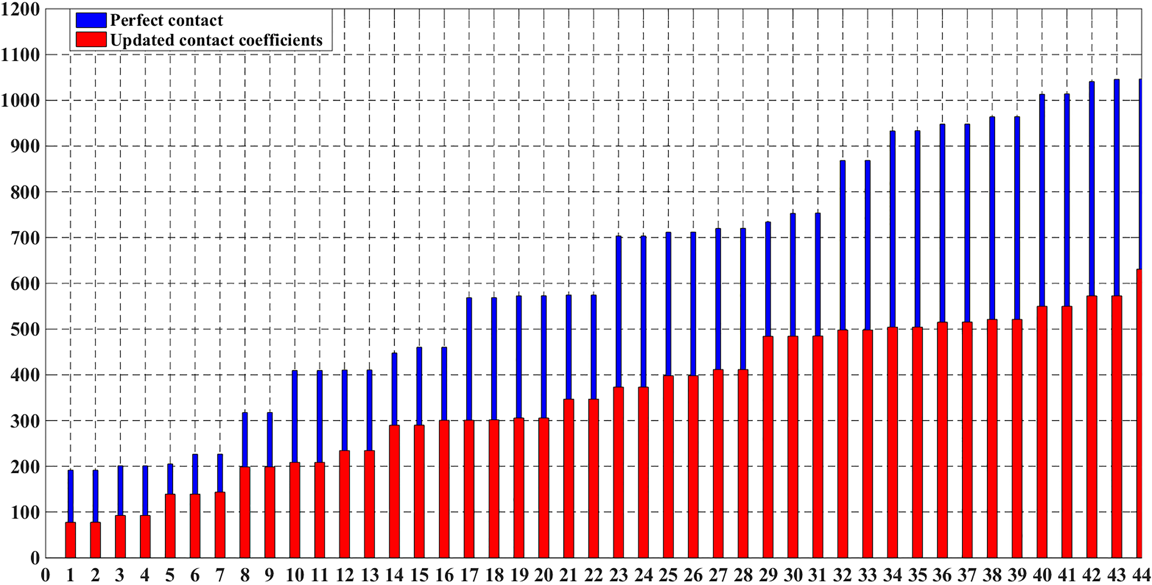
This study uses both magnetic and mechanical models separately. The magnetic model is used to compute magnetic flux densities in the air gap which serve to calculate the magnetic pressure normal and tangential components. Then, a harmonic analysis is performed in order to determine the frequencies of the magnetic load applied on the stator structure. The structural mechanical model is then used for a constrained structural analysis which computes the corresponding displacements and deformations for each harmonic of the magnetic pressure. In this case, the applied loads have a sinusoidal waveform as indicated in Eq. (1):
Where (m) and (n) are respectively the circumferential and longitudinal modes number identified in the correlation phase and P
Structural analysis under static magnetic loads results
View on displacement sensors locations.
Example of Ux displacement for the 27th harmonic of the magnetic pressure at drive-end (DE) on a circular path.
This study shows that the harmoncis number 27, 3, 24 and 0 are responsible of a high level of deformations (displacements) as shown in Table 3. Figure 10 shows the Ux displacement for the 27th harmonic of the magnetic pressure at drive-end (DE) on a circular path as illustrated in Fig. 9.
In this case, first the local magnetic forces are computed on a magnetic mesh support as illustrated in Fig. 11. Then, these forces serve as input parameters for the mechanical model and are applied by the same way on the key points created on the mechanical structure at the stator bore tooth faces.
View of the magnetic forces distribution.
Time varying displacement Ux (m) at NDE and its harmonics.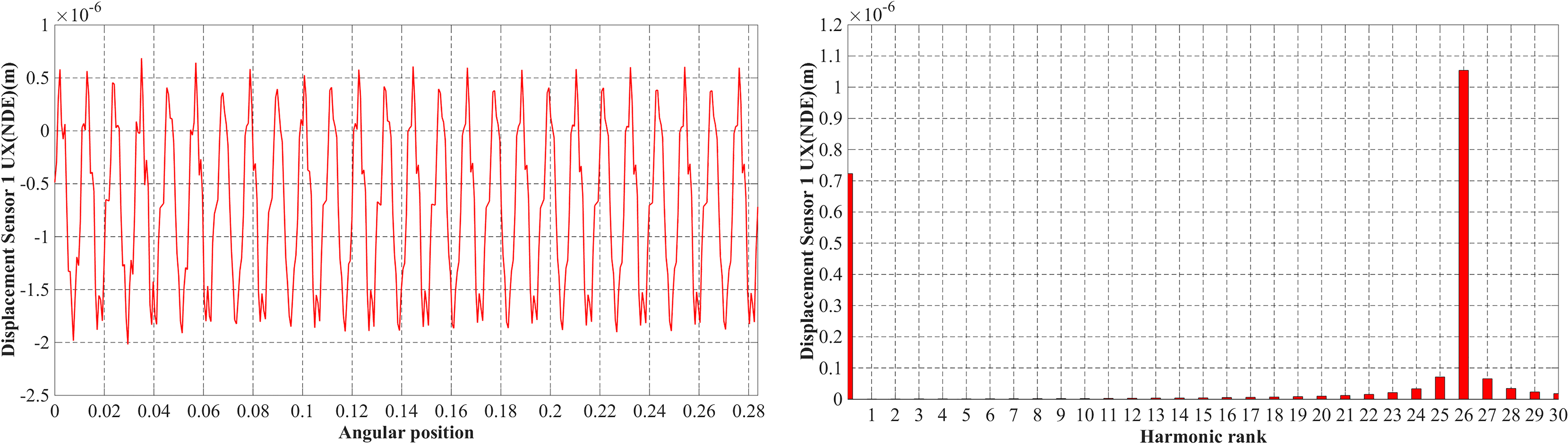
The vibration behaviour investigation is done for a fixed rotational speed equal to 228 rpm and the displacement (Fig. 12) have a consequent frequency equal to 92.1659 Hz, which is approximately equal to 24 times the rotational frequency (228/60
Test setup presentation
The test setup used for the experimental measurements is presented in Fig. 13 and listed below:
Presentation of the test setup.
Flexible coupling for connecting the motor with the frame. Piezoelectric sensor mounted on the frame. Tested electrical motor. Vibration measurement acquisition equipment. Motor supply, control and temperature monitoring.
In this section, the experimental measurements, for both loaded and no-loaded configurations, are given in Figs 14 and 15.
Motor (loaded) 280 rpm, 112 Hz vibration (measured on frame).
Motor (no-loaded) 280 rpm, 112 Hz vibration (measured on frame).
Figure 14 for a rotational speed equal to 280 rpm the measured displacements when the electric motor is loaded, while Fig. 15 the measured displacements when the motor is not loaded. Based on these facts, one can note that the measured vibrations are not related to the coupling or the load and also it appears that the vibration frequency is proportional to the rotational speed. For the case when the speed is equal to 280 rpm, the vibrations frequency is equal to 112 Hz which is equal to 24 times the rotational frequency. While, for the case where the speed is equal to 320 rpm, the vibrations frequency is equal to 128 Hz which correspond also to 24 times the rotational frequency. Actually, 24 times the rotational frequency is nothing but twice the machine’s electrical frequency.
In the structural analysis under time varying loads and from the obtained displacements harmonics, one can note that the number of poles 24 is responsible for a high level of vibrations. While, the structural analysis under static loads shows that the harmonics 27, 3, 24 are responsible of considerable deformations. Adding to this, the findings from experimental measurements which confirm the obtained results from the FE simulations and points the poles number influence on the vibrations in this kind of machines. One can then conclude that the stator slots and rotor poles combinations are determinant for the level of vibrations. As a matter of facts, to reduce the level of vibrations, one can act on the poles and slots number in the predesign phase if possible. If not, one can act on the stiffness of the frame even by increasing its thickness or by adding reinforcements (brackets, bars…) as proposed in Fig. 16.
Presentation of the frame reinforcement’s techniques.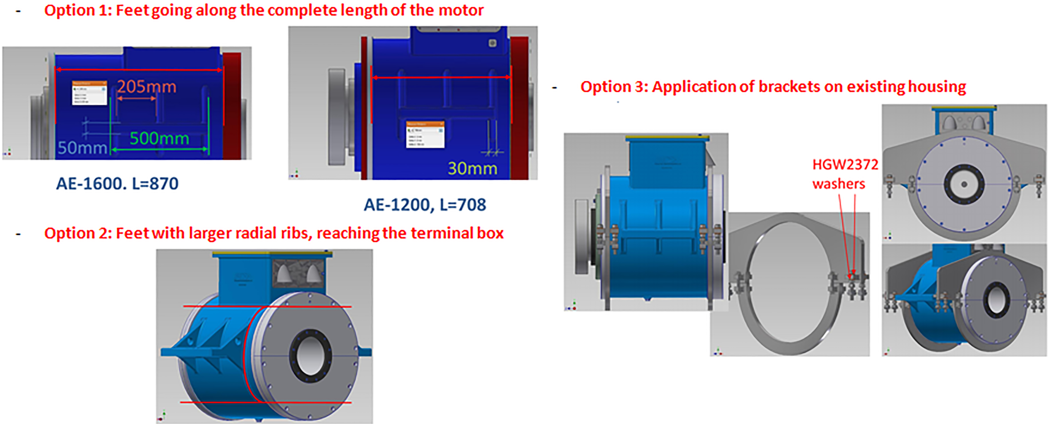
This article detailed the process of vibro-acoustic analysis of an electrical motor due to electromagnetic origins and took into consideration the contact coefficients. It can be then concluded, first that the corresponding measured vibrations are then due to electromagnetic origins using structural analysis under time varying magnetic loads. Second, the modal analysis showed that the structure natural frequencies may not be excited via the electromagnetic forces as their frequency range is located a little far from the main harmonics of the magnetic pressure. In fact, this doesn’t mean that there are no vibrations but that the obtained ones are mainly due to the rotating distributed magnetic force (structure deformation). Finally, the static load structural analysis allowed to calculate the vibration amplitude for each harmonic rank of the magnetic pressure and to determine that the higher vibrational levels are obtained for the harmonics ranks located in the range: (27–24).