This paper deals with the acoustic noise emitted by AC variable speed drives. It proposes an original method to reduce the noise of magnetic origin using carriers of different frequencies to control the PWM of the inverter. The method is based on an analytical model which makes it possible to determine with accuracy the parameters of the carriers. The method is applied and validated with a 15 kW induction machine.
The scientific literature is very rich with respect to the problem of magnetic noise generated by three-phase AC machines [1, 2, 12] and to reduce it with control PWM inverter [11]. At variable speed, the PWM power supply is responsible of additionnal noise components of high amplitude [7, 6, 9, 3]. To reduce these acoustic effects, a filter can be connected to the inverter outputs but it induces additional costs and increases the size of the device. The architecture of the converter can also be modified to minimize the voltage variation amplitude during the switching with multilevel converters [8]. Otherwise, many PWM control strategies have been proposed to control the effects due to the switching [10]. In order to better control the acoustic effects, a method has been developed to analytically characterize the switching harmonic spectral contents of the signals applied to the stator windings [5]. Moreover, this method also makes it possible to predetermine how these spectral contents evolve when particular strategies are implemented in order to avoid exciting a stator frame natural frequency [4]. The main objective of this paper is to show that it is possible to obtain interesting results in terms of magnetic noise reduction when three distinct carriers of different frequencies are used. To optimize the choice of these frequencies, the analysis uses the notion of equivalent schemes to characterize the behavior of this structure for each harmonic. Experiments carried out on an induction machine (IM) validate the proposed control strategy. A lower index “q” will be assigned to the mathematical variables to designate the considered phase ( 1, 2 or 3).
IM connected to a three-phase PWM inverter.
Theoretical approach
The theoretical developments are based on the structure shown in Fig. 1 where the used notations are specified. The principle consists in substituting for the single triangular carrier, characteristic of the traditional PWM, three triangular carriers of same amplitude but of different frequencies. The control strategy at the level of each phase is similar to that defined for a classical PWM. In order to be able to predetermine the impact of such a control law on the ( 1, 2, 3) harmonic content, hence on the switching magnetic noise, an analytical method has been developed. It consists in substituting sinusoidal carriers for the triangular carriers. As the properties established for sinusoidal carriers are exploited to define the inverter control strategy used for the experiments implementing triangular carriers, upper indexes (s) and () are used, if necessary, to distinguish the variables according to the carrier waveforms. The main interest of using sinusoidal carriers for the modelling is to be able to analytically express in a simple way the spectral content and, consequently, the content of the variables, knowing that the homopolar components can not be found in the voltage system. The reference waves of frequency and the carriers of frequencies, where represents the phase modulation index, will be denoted by and . For a adjusting coefficient equal to the unit and considering a time referential tied to , noting , and are expressed as: and . is a phase adjustable carrier phase difference and . Let us introduce and positive or null integers and the quantities:
can be expressed as:
where:
and
switching three-phase harmonic systems generated for only one sinusoidal carrier and 48
0
1
2
3
4
(a):
0
m; (H); 100
2m+1; (C); 33.3
3m+2; (A); 20
4m+3; (H); 14.3
5m+4; (C); 11.1
1
2m-1; (A); 33.3
3m; (H); 11.1
4m+1, (C); 6.7
5m+2; (A); 4.8
6m+3; (H); 3.7
2
3m-2; (C); 20
4m-1; (A); 6.7
5m; (H); 4
6m+1; (C); 2.9
7m+2; (A); 2.2
3
4m-3; (H); 14.3
5m-2; (C); 4.8
6m-1; (A); 2.9
7m; (H); 2
8m+1; (C); 1.6
4
5m-4; (A); 11.1
6m-3; (H); 3.7
7m-2; (C); 2.2
8m-1; (A); 1.6
9m; (H); 1.2
(b):
0
1; (C)
m+2; (A)
2m+3; (H)
3m+4; (C)
4m+5; (A)
1
m-2; (C)
3; (H)
m+4; (C)
2m+5; (A)
3m+6; (H)
2
2m-3; (H)
m-4; (A)
5; (A)
m+6; (H)
2m+7; (C)
3
3m-4; (A)
2m-5; (C)
m-6; (H)
7; (C)
m+8; (A)
4
4m-5; (C)
3m-6; (H)
2m-7; (A)
m-8; (C)
9; (H)
The Table 1 gives, for the first values of and , the theoretical ranks of the harmonic contents for a single sinuoidal carrier such as: . For each three-phase harmonic system, the phase sequences: clockwise (C), anticlockwise (A), homopolar (H) are specified as well as the relative magnitudes expressed in percent defined as: (as for given , the magnitudes only depend on and , these values are only given for ).
Analytical, numerical and experimental comparisons between and variables, considering various cases, show that this analytical model leads to define accurately the ranks, the phases and the phase sequences of all the harmonic systems with an error on the harmonic magnitudes. This amplitude error is not very annoying with regard to the problem treated in view of the relatively large uncertainties which accompany the various analysis carried out in order to predetermine the IM magnetic noise, particularly for unconventional power supplies. The main advantage of this model concerns these determinations which do not require any calculation of the switching instants. Moreover, it appears that these particularities are valid for synchronous or asynchronous PWM whatever the value. Let us point out that in the following and , .
Carrier of different frequencies
The principle assumes that differs with satisfying the equalities: , . Relationships (1) to (4) lead to switching harmonic ranks which are defined by families centered on with …These ranks are expressed by:
where
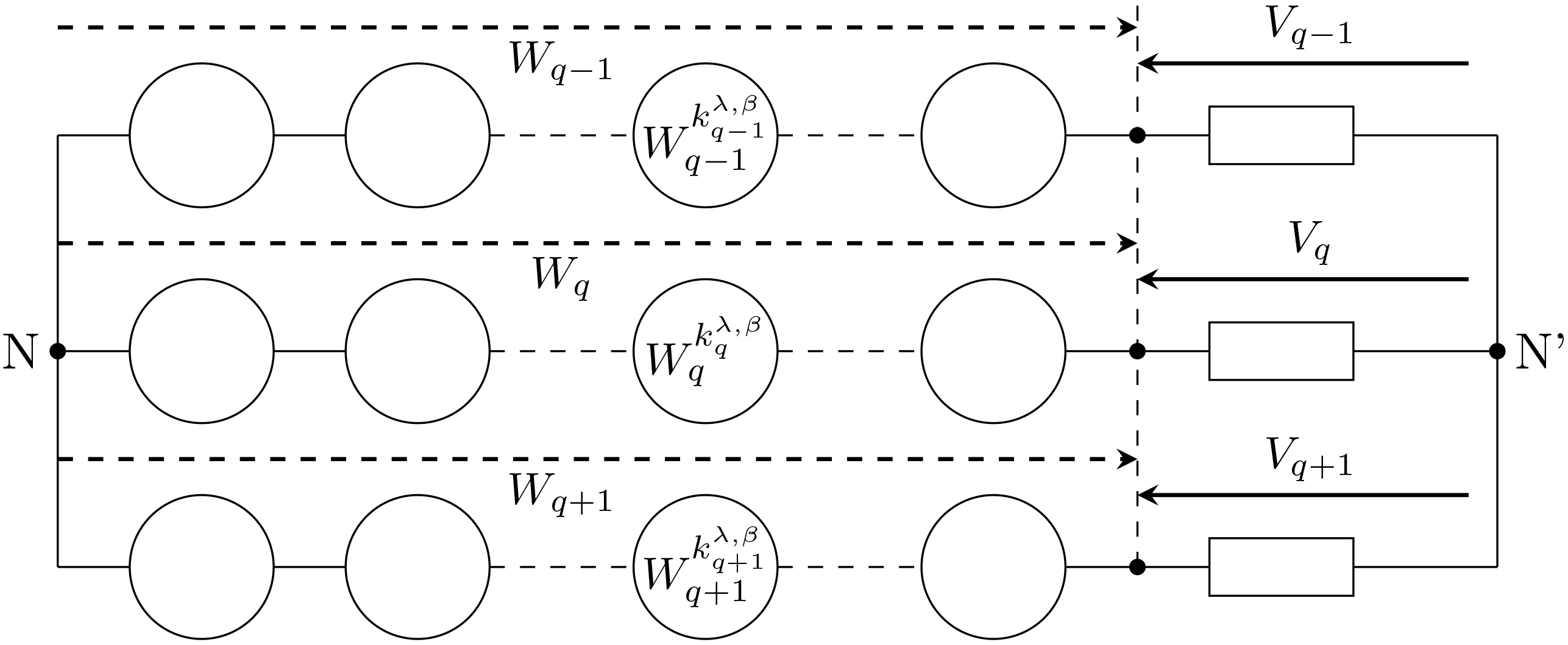
Equivalent structure of the converter associated to the IM.
Let us point out that 1, 3, 5, 7, …harmonic ranks are independent from . So, in the following, only the harmonic ranks dependent on are considered. It results that the structure in Fig. 1 can also be presented using the scheme given in Fig. 2 where an harmonic rank must also be distinguished according to the considered phase. It results that this rank will be denoted as: . Each generator is characterized from the analytical model.
Different configurations with of the equivalent circuit.
To analyze how an harmonic of rank modifies the IM magnetic noise, the superposition principle is applied and the generator giving a signal of frequency is searched for each phase. Then, after identification of these different generators, all the others are switched off. It results that 3 cases have to be considered: this harmonic exists on the 3 phases (Fig. 3a), it exists only on 2 phases (Fig. 3b for example), it is present in only 1 phase (Fig. 3c for example). For this harmonic, the equivalent scheme corresponds to one of the three circuits presented in Fig. 3 by adapting the positions of the generators according to the active phases in Fig. 3b and c. It seems obvious that with this strategy, the three-phase harmonic voltage system of rank is unbalanced and that it is necessary to characterize the IM behavior in terms of noise considering its (C) and (A) components.
In order to illustrate this procedure, the harmonic content of the variables is determined by associating the index with phase 2. By adopting a central modulation index of 48 with , it comes: , and . Taking account of (6), the ranks of the different voltage harmonics are given in Tables 2. Table 3 presents the relative amplitudes of the various components deduced from the numerical values specified in Table 1.
Switching harmonic components for carrier frequency shift
Phase 1
Phase 2
Phase 3
1
39 2
48 2
57 2
2
78 (21)
96 (21)
114 (21)
3
117 2
144 2
171 2
4
156 (21)
192 (21)
228 (21)
Analytical predetermination of the voltage content for . (a) Only one carrier (b) Three-phase carrier system.
Relative amplitudes of the various components
0
1
2
3
4
1
100%
33.3%
6.7%
2.9%
1.6%
2
33.3%
20%
4.8%%
2.2%
1.3%
3
11.1%
20%
14.3%
3.7%
1.8%
4
6.7%
14.3%
11.1%
3%
1.5%
Table 2 shows, for the values of and which appear in the preceding tables, that the extreme ranks are 31 and 237 so that, for 50 Hz, a frequency range between 1550 Hz and 11850 Hz.
It is obvious that correspondences in terms of ranks over the three phases exist but, for a given value of leading to a harmonic of amplitude sufficiently significant on one of the phases, the value of for, at least, one of the two other phases will be too much high resulting in a harmonic of virtually zero value as indicated in Table 3. Therefore, case 1 (Fig. 3a) previously defined has to be excluded from the possibilities offered. By limiting the values to 4, Table 2 shows that case 2 (Fig. 3b) can only occur by considering the families relative to for phase 1 and for phase 3 insofar as the central ranks which characterize these families (117 and 114) are sufficiently close. Consequently, there are seven concerned ranks defined by odd values in the range 111–123.
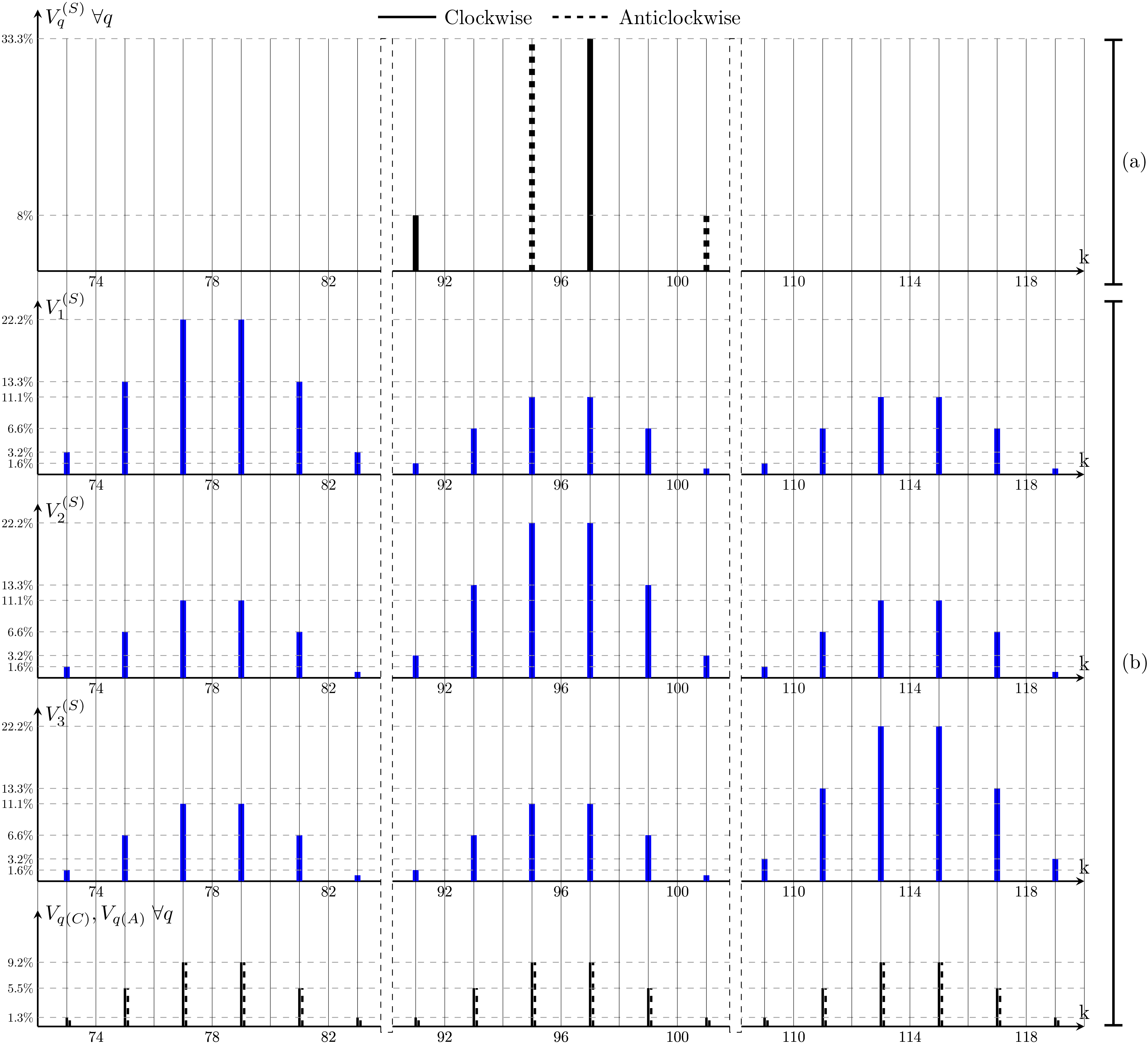
By way of example, Fig. 4 shows, for the previous values of and and considering the components relating to , the theoretical determinations of the voltage components. Two cases are presented
a three-phase system of sinusoidal carriers (Fig. 4b) ignoring the interactions between phases 1 and 3 which only significantly affect the components of ranks above 112.
Positions of the accelerometers on the IM.
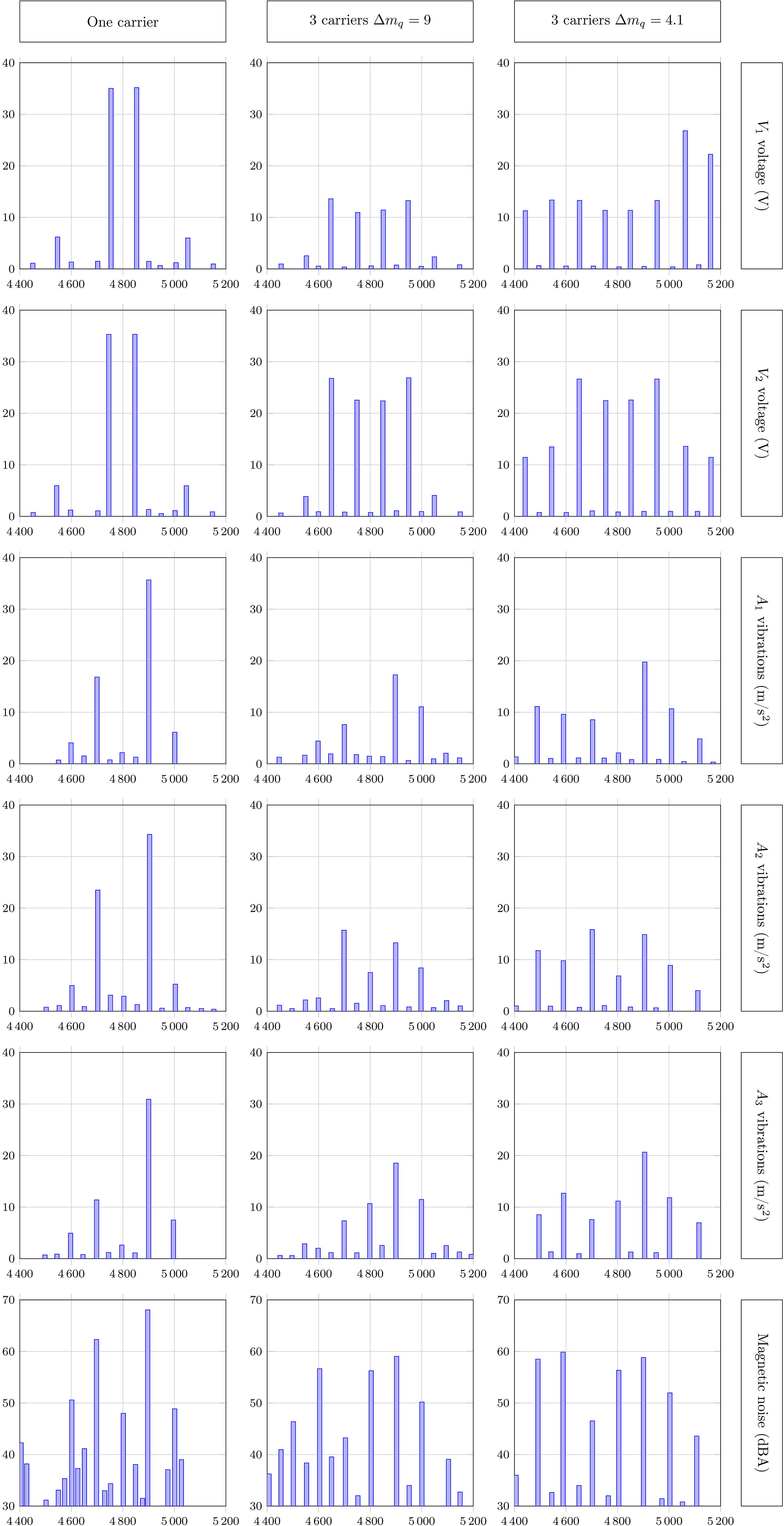
Voltages, vibrations and noise for and values.
For a single carrier, is distinguished by the absence of components of ranks 3 which form a (H) system (Table 1). For the three-phase carrier system, the 3 rank components are involved in the definition of voltages. The determination of (C) and (A) components denoted and and , is carried out by considering only case 3 (Fig. 3). Under these conditions, using the time phasors, it comes: , with , leading to: and .
IM magnetic noise reduction
The considered cage IM presents the following characteristics: 15 kW, 50 Hz, 2,380 V, 24.8 A, 48, 36. The nodal analysis shows that this IM is particularly sensitive to frequencies around 2800 Hz, 3800 Hz, 4800 Hz and 6200 Hz. In view of the imbalance which affects harmonic three-phase systems for carriers of different frequencies, the mechanical responses of the IM external housing are more complex so that the IM has been equipped with 3 accelerometers as shown in Fig. 5. The microphone is located approximately in the axis of A1 at a distance of 90 cm. In order to characterize the carriers, the numerical values used for the predetermination of the voltage systems are used. The experimental results obtained (voltages, radial vibrations, magnetic noise) presented in Fig. 6 correspond to triangular carriers and relate to the components such as for which the slotting effect is practically nil. The range of frequencies used to present the results is between 4400 Hz and 5200 Hz (ranks 88 to 104). On this range, there is a very pronounced resonance at 4800 Hz. The cases treated correspond to:
a single carrier with ,
three-phase carrier systems such as and
Sets of spectral lines which satisfy the theoretical predeterminations (Fig. 4) appear in the voltages. The fact that an integer value has not been chosen for makes it possible to reduce the spreading of the spectra while eliminating interactions between phases in order to characterize a three-phase harmonic system considering only the case 3 (Fig. 3c).
To estimate the force component amplitudes, the different results will be evaluated relative to each other by assuming that the fundamental air-gap flux density peak value is equal to 1 T (100%). It can be deduced that the harmonic rotating flux density waves have for amplitudes values of the order of:
3.5 10 T for the components of ranks and 5 10 T for components of ranks for a single carrier,
9.6 10 T, 5.7 10 T and 1.4 10 for the components whose ranks are respectively , and for three phase carriers systems.
These harmonic flux density components have very small amplitudes, so that considering only the double products involving the fundamental flux density component to characterize the radial force spectral contents, and consequently those of the vibrations, is perfectly justified. Under these conditions, in particular for a three-phase carrier system, at a given frequency, two force components act on the stator housing, the distinction is essentially based on the mode numbers which is either 0 or 4. The other highlight, already noted elsewhere, is that force component of mode 4 dominates in terms of vibrations and noise. The experiments clearly show that the three-phase carrier system acts very significantly on the radial vibrations, leading to a reduction of the main noise spectrum lines of practically 10 dBA.
Conclusion
In this paper, an original method has been presented for reducing the noise of magnetic origin of AC machines supplied by inverters. The PWM is responsible for noise components of high amplitude. Instead of increasing the PWM frequency, the authors proposed a new strategy of PWM based on the use of 3 carriers of different frequencies. I has been shown that the parameters are determined with an analytical model which has the advantage of the time computation. The proposed strategy for reducing magnetic noise has been applied to an industrial induction machine supplied by an inverter for 2 different adjustements of the carrier frequencies. The measurement of the acoustic noise compared to the initial spectrum shows the effect of the method: it results in spread spectra with a significant reduction of the amplitudes of the various noise components.
References
1.
Harmonic theory of noise in induction motors, Electrical Engineering59(12) (1940), 1148–1149.
2.
BesneraisJ.L., Fast prediction of variable-speed acoustic noise due to magnetic forces in electrical machines, 2016, pp. 2259–2265.
3.
BesneraisJ.L.LanfranchiV.HecquetM. and BrochetP., Characterization and reduction of audible magnetic noise due to pwm supply in induction machines,IEEE Transactions on Industrial Electronics57(4) 2010, 1288–1295.
4.
BrudnyJ.F.MorgantiF.LecointeJ.P. and ParentG., On the use of carrier phase jumps to reduce some pwm switching effects, In IECON 2014 - 40th Annual Conference of the IEEE Industrial Electronics Society, 2014, pp. 762–768.
5.
BrudnyJ.F.SzkudlapskiT.MorgantiF. and LecointeJ.P., Method for controlling the pwm switching: Application to magnetic noise reduction, IEEE Transactions on Industrial Electronics62(1) (2015), 122–131.
6.
CovicG.A. and BoysJ.T., Noise quieting with random pwm ac drives, IEE Proceedings – Electric Power Applications145(1) (1998), 1–10.
7.
da SilvaE.R.C.dos SantosE.C. and JacobinaB., Pulsewidth modulation strategies, IEEE Industrial Electronics Magazine5(2) (2011), 37–45.
8.
MalinowskiM.GopakumarK.RodriguezJ. and PerezM.A., A survey on cascaded multilevel inverters, IEEE Transactions on Industrial Electronics57(7) (July 2010), 2197–2206.
9.
Ruiz-GonzalezA.Meco-GutierrezM.J.Perez-HidalgoF.Vargas-MerinoF. and Heredia-LarrubiaJ.R., Reducing acoustic noise radiated by inverter-fed induction motors controlled by a new pwm strategy, IEEE Transactions on Industrial Electronics57(1) (2010), 228–236.
10.
Ruiz-GonzalezA.Vargas-MerinoF.Heredia-LarrubiaJ.R.Meco-GutierrezM.J. and Perez-HidalgoF., Application of slope pwm strategies to reduce acoustic noise radiated by inverter-fed induction motors, IEEE Transactions on Industrial Electronics60(7) (July 2013), 2555–2563.
11.
UedaS.HondaK.IkimiT.HombuM. and UedaA., Magnetic noise reduction technique for an ac motor driven by a pwm inverter, IEEE Transactions on Power Electronics6(3) (1991), 470–475.
12.
ValaviM.NysveenA.NilssenR. and RølvågT., Slot harmonic effect on magnetic forces and vibration in low-speed permanent-magnet machine with concentrated windings, IEEE Transactions on Industry Applications50(5) (2014), 3304–3313.