



Abstract
As an integral part of Strapdown Inertial Navigation Systems, ring laser gyroscopes (RLG) are exposed to joint loading conditions where thermal, static and dynamic loads occur simultaneously. The effects of different loading conditions on overall RLG performance should be addressed in parallel for an optimum design. A crucial aspect in this process is the development of the path length controller (PLC), consisting of a mirror, a composite piezo electric bending actuator and other motion transfer elements. This study presents an analogy between the external loading (static, dynamic, thermal, and vibration) on PLC and the RLG signal stability, which has been studied only partially in the open literature. 5 different PLC designs are analyzed through finite element method and the results are validated experimentally using the composite piezo electric bending actuator by mode-scanning and PZT feedback tests. Obtained results illustrate the axial and the radial displacement (also named mirror tilt) capacity of different PLC designs. Disruptive effects of radial displacement of the PLC mirrors on RLG signal stability are observed. The study is concluded with the classification of different PLC designs for distinctive loading conditions, which is believed to be valuable for the aerospace industry.
Keywords
Introduction
Strapdown Inertial Systems are being used extensively by aerospace industry for navigation and guidance. Modern Strapdown Inertial Navigation System (SINS) is a set 3 accelerometers and 3 gyroscopes, which are used to track motion and its rate for 6 degrees of freedom (DOF) (see e.g. [1,2]). Ring laser gyroscope (RLG) is a rotation rate sensor with industry leading performance properties such as bias stability, and dynamic range (see e.g. [3]). Moreover, Strapdown Inertial Navigation Systems uses RLG extensively for military (aircraft, missile, submarine navigation) and commercial (mining, platform stabilization) applications. The sensing principle of RLG relies on the Sagnac Effect (1913) where two identical counterpropagating beams in a cavity frame shows a phase change which is proportional to the frame rotation rate (see e.g. [4]). Cavities designed to observe Sagnac Effects are named Sagnac interferometer. To construct a Sagnac Interferometer, RLG design consists of a frame and reflective mirrors (3 or 4 mirrors). Laser waves are emitted inside the interferometer to build a laser resonator which is the main element of the RLG. In order to obtain laser resonance condition, the total distance between mirrors also known as the path length is designed as integral multiples of standing longitudinal laser wavelength. This requirement to hold the path length as a multiple of the complete wavelength is to fix the resonator mode, the gain profile and to obtain a stable output signal. When this condition is not satisfied, failure of the oscillation condition occurs because of the interference of laser waves inside the cavity. A review, on the model of RLG geometry, by the evaluation of mathematical expression of the resonator geometry, outlined the importance of the path length stabilization on the RLG performance in [5].
However, dimensional stability is impossible to achieve since production methods are limited to provide nanometric tolerances which is one of the reasons why manufacturers complain about the reproducibility of RLGs [6]. Moreover, path length tends to change under thermal loadings because of the thermal expansions. To minimize the distortions caused by thermal expansions and the thermal instabilities, RLG parts are produced using Ultra Low Expansion (ULE) glass and low thermal expansion metals such as invar alloys. Therefore, the path length controller (PLC) is used to control the path length in order to fulfill stabilization requirements [7]. In the literature, closed-loop path length control algorithms are designed where sensor signals are gathered using photodetectors. Signal levels are analyzed and compared between counterpropagating beams by a control scheme to arrange path length using PLC. PLC consists of a reflective mirror (usually concave) and a composite piezo electric bending actuator (it consists of piezo elements (Pb(ZrTi)O3 material, PZT) and other motion transfer elements (metal membrane, disc, bolt)). Figure 1(a) shows the structure of a 4 mirror RLG and (b) shows the structure of a PLC.
Moreover, the arrangement of the path length is established by the vertical movement of the PLC. The vertical movement of the PLC is established by the contraction and relaxation of the PZT elements. When an arrangement signal arrives to the PLC controller, a control voltage is applied on PZT discs. The contraction of the PZT is transferred to mirror by the bolt and the disc.
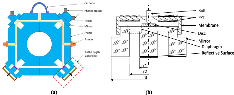
(a) RLG Structure; (b) PLC Structure.
The aim of the PLC design is to have the maximum vertical deflection to increase the control capability. Nevertheless, the motion transfer can result in horizontal deflections also known as anti-transverse-deformation capability (or mirror tilt) which distorts the laser beam inside cavity and disturbs the signal stability [8,9]. Figure 2 shows deflections of the PLC mirrors.
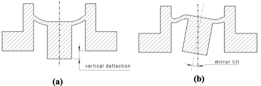
Deflections of a PLC mirror (a) Vertical Deflection; (b) Mirror tilt.
In this context, an analytical expression for the vertical displacement of the path length controller using elastic shell theory for a two-diaphragm concave mirror is obtained and correlated to FEA with 4.7% error in [10]. A parametric design optimization study with FEM to maximize the vertical deflections and to minimize mirror tilt is pursued and the results are validated for the optimum design using a mode-scanning test in [8]. Another optimization study is conducted in [11] for the determination of PZT type and membrane geometry of the piezo transducer/membrane (also called piezo transducer) assembly for the same purpose and as a result, the vertical deflection is increased up to 6,48 μm using FEA methodology. In [12], metal membrane design is specified as the main part defining vertical deflection capabilities and different design methodologies are given to arrange its stiffness. Another approach to solve the thermal dimensional instability problem is developed by using piezo transducer as a passive thermal compensation element in [13]. So, the contractions of the resonator frame are balanced with the elongations of piezo transducer. These studies consider mostly static loading to observe mirror deflections and take into account the vertical and horizontal stiffness of a single PLC design to increase control range and to reduce mirror tilt. However, aerospace systems are exposed to joint loading conditions where thermal, static and dynamic loads occur simultaneously. Moreover, the effects of temperature variations are reduced to thermal expansions in the literature (see e.g. [13]). Therefore, a complementary study containing all loading conditions is needed in the literature.
Although the problems stated above are partially solved by means of dimensional optimizations, different structural designs are studied by researchers. This study aims to analyze 5 different existing PLC designs in detail by taking into consideration the combined effects of disruptive loadings using optimized dimensions stated in the literature. The comparison is made by using finite element analysis for static structural, dynamic transient, thermal structural loadings and for modal responses. Results are validated experimentally from photodetector signals for alternative-1 and alternative-3. We extend the analysis to 5 different PLC designs for all loading conditions. Deflections of the reflective surfaces are also studied under dynamic loads (dither loads) and under pressure loads caused by temperature variations. In this regard, the current study is unique for the classification of PLC designs under different distinctive loading conditions and aims to assist industry in selecting proper PLC design.
The paper is organized as follows. After presenting an illustrative introduction here, Section 2 addresses shortly different PLC design options and a detailed finite element analysis to explain simulation method and results. Section 3 studies the validation of the numerical analysis through experiments. Then the study is concluded in Section 4.
Figure 3 shows alternative PLC designs found in the literature [14–19]. A comparative study of different PLC designs is not performed before in the literature, which is crucial for the identification of suitable PLC for different loading conditions. First alternative shows a typical single diaphragm design. This diaphragm is moved near the reflective surface and an additional diaphragm plate is optical contacted on the upper surface to construct alternatives 2 and 3. The difference between these alternatives is the location of the disc. These three designs use a low thermal expansion metal membrane to hold piezo elements (PZT) and to transfer vertical motion to mirrors. The last 2 alternatives are designed using ultra low expansion glasses for PZT holding membranes. Materials used in alternative designs are given in Table 1. Important dimensions of the mirrors are shown on Fig. 1(b). A consistent sizing is applied to all alternatives after the literature survey. Mirror center (r1), base (r2) and outer (r3) radius is same for all alternatives and equal to 60r, 45r and 15r respectively. Diaphragm thickness is 3r for dual diaphragm designs and 4r for single diaphragm design (alternative-1).
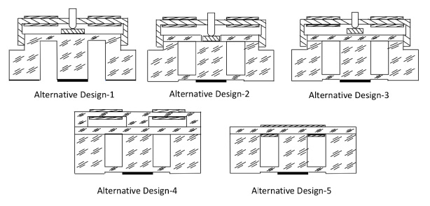
Alternative mirror designs.
Material list
FEA is a powerful mathematical modeling method to simulate structural responses of the mechanical designs. MSC Software Marc/Mentat® is used in this study for static, dynamic, thermal and modal analysis. Material parameters are presented in Table 2. Before starting with the detailed analysis, the effects of the PZT discs on dynamic and thermal responses are checked. The effect of the PZT discs on final results is found to be less than 2.5%. Therefore, anisotropic structural PZT material is neglected in these models to reduce computational costs. Anisotropic properties used in this preliminary study is given subsequent to Table 2.
Material properties
Anisotropic PZT Properties are; C11: 6,7 e10 (Pa), C12: 3,4 e10 (Pa), C13: 3,1 e10 (Pa), C22: 6,7 e10 (Pa), C23: 3,1 e10 (Pa), C33: 5,0 e10 (Pa), C44: 2,2 e10 (Pa), C55: 2,2 e10 (Pa), C66: 2,4 e10 (Pa), Density: 7000 (
Even though the geometry is appropriate for axisymmetric modeling for most of the loading conditions, 3D solid elements are preferred here. MSC Marc® HEX8 type 7 elements are used for the analyses. Glue contact is assigned for the connections between the parts of the assembly. The only exceptional contact is the connection between the bolt and the disc where a touching contact is assigned. The computational cost is reduced through procedure files which decreases the preparation time. An example model is given in Fig. 4 to show the mesh used for alternative design-1. The results for all loading conditions will be discussed later.
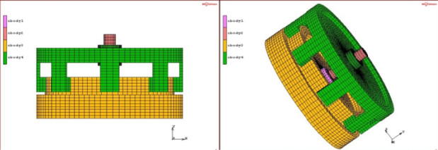
Solid mesh of alternative design-1.
Benchmark study starts with the static structural analysis that is pursued for mirror design comparison. 3 loading conditions are applied: axial, radial and moment, which are shown in Fig. 5. In each case 10 N force is applied.
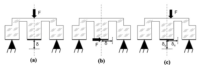
Static structural analysis definition (a) Axial (b) Radial (c) Moment.
Axial loading is used to specify the axial stiffness of the mirror. In the literature, it is advised to have the same vertical stiffness for mirror and membrane (piezo transducer) geometry in order to increase the control capability of the PLC [11].
Radial and moment loadings are used to discover mirror tilt capability of the mirrors. Minimized mirror tilt is an important system requirement to establish a stable output signal. In the literature, the reasons for the mirror tilt are given as listed below:
Non-homogeneity of mirror material. Non-homogeneity of electrical field over PZT discs. Piezo transducer assembly mistakes (non-parallel bonding of PZT and metal membrane) Non-concentric bonding of disc and mirror
Therefore, radial and moment loadings are used to simulate these reasons. For moment loading the load is applied 0.5 mm away from the central axis which simulates a feasible assembly mistake. Since alternative 4 and 5 shares the same mirror design, results are shared together in Table 3.
Analysis results
The results show that under static loading alternative 2-3-4-5 has lower axial and radial deflections when compared to alternative-1. These low deflection values imply that the position of reflective surface will be maintained under static loading (such as bolt pretension). The moment loading is done to simulate assembly mistakes such as a slip-on bolt assembly, a form defect on bolt end, thickness variation in adhesives or a concentricity failure between PZT and membrane. The results show that using a dual diaphragm design (such as alternative 2-3-4-5), deflections can be decreased 60% under axial loading, 70% under radial loading and 40% under moment loading. Here, the axial and the radial deformations can be used in order to calculate the stiffness values to match the stiffness of the membrane geometry as recommended in the literature. However, in this chapter, the aim is the characterization of the mirror response under different loading conditions. Hence, the deformations of the reflective surface are found more relevant to characterize the mirror response since this deformation is directly related to the path length (e.g. it is known that for square RLGs at least 0.2237 μm axial displacement is needed in the PLC to arrange the path length one integral wavelength (0.6328 μm)).
The need for a dynamical analysis in design comparison comes from a phenomenological problem of the RLG which is defined as lock-in. It can be defined as a rotation insensitivity for slow rotation rates. So, RLG has a dead band in frequency difference (Δω, sensor output) for low rotation rates (Ω) [23–25]. Different methods are defined to solve lock-in dead band problem such as constant bias, alternating bias, magnetic mirrors or mechanical dithering. Here, mechanical dithering will be discussed, because its application creates a harmonic load on the PLC which enforces mirror tilt.
Mechanical dithering is a method where a piezo transducer named dither is used to oscillate RLG from its rotation axis. Usually, dither has two inputs for its piezo elements which are the supply signals amplitude and frequency. Here, signal amplitude is used to control the oscillation angle and signal frequency is used to control the oscillation rate. Many design optimization studies are conducted to optimize the geometry of the piezo transducer and to increase its performance in order to repress lock-in deadband. In the literature, FEA method is used for the design optimization of dither mechanism (see e.g. [26]). A comparison between numerical equation, test results and FEA has shown that finite element analysis method was able to identify peak amplitude with only 1.3% error. A sensitivity analysis on the dimensions of the piezo transducer, showed the geometrical dependencies of the structure in [27]. Experimental validations in these studies showed significantly the success of finite element analyses for this application. Moreover, the disruptive effects of a coupling between dithering motion and external vibrations is analyzed in [28] by the construction of a set of equation for kinematic response of the RLG to decouple motions. Additionally, the effects of a misalignment between dither mechanism central axis and RLG central axis is observed and associated to sensor outputs in [29]. Although, dither mechanism related errors on the RLG performance are widely studied in the literature, a particular study of dithering motion and its effects on the RLG subsystems such as PLC is not performed.
However, in this study, a test bench is designed to observe particularly the effects of the dithering motion on PLC structure to understand the necessity of the dynamic analysis. Same test bench is used for the subsequent validation studies which are detailly explained under experimental observations section. Initial test (called PZT feedback test) on alternative design-1 showed that the photodetector signals of the RLG can be overridden by increasing the amplitude of the dither signal for the same frequency. This test showed that an inertial force occurs at the center of the mirror which deflects the mirrors reflective surfaces and disturbs output signals. Figure 6 shows the test setup and the results. For Fig. 6(b) dithering is done using 25 VDC signal amplitude and ∼450 Hz frequency and in Fig. 6(c) dithering is done using 8 VDC signal amplitude and ∼450 Hz frequency. Also, in this test, PLCs piezo elements are used to collect vertical movement (Δy) data instead of controlling the path length. The change in the position of mirror center is obtained indirectly by reading piezo disc voltage. Results showed that an increased dithering amplitude overrides the photodetector signals (PD, shown blue) and creates voltage on piezo discs (shown magenta). The two signals share the same dithering frequency which also implies the effects of the dithering on the position of the reflective surfaces.
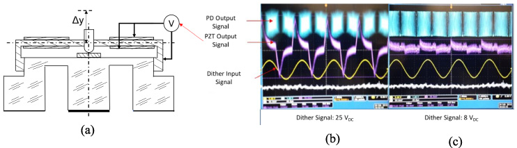
(a) Dithering test bench (b) Results for 25 VDC (c) Results for 8 VDC.
The initial results show the importance of the dynamic stability for the output signals. Therefore, the comparative study is expanded to include the dynamic effects. MSC Marc® Dynamic Transient solver is used for this problem. In order to observe the mirror tilt, the model shown in Fig. 7(a) is prepared where the mirror contact surfaces are linked to the center of the RLG with RB2 elements. The center node is defined as retained (reference) node. The dither motion is simulated with rotational movement. Two consecutive sinus waves are applied to the retained node. To observe tilting motion resulting from inertial effects, the motion of the reflective surfaces center node is tracked and compared with its kinematical reference position (Kinematic reference motion is defined as the motion if the PLC makes rigid body motion without inertial forces). The discrepancy between FEM position and kinematic position (Δ = |Ref. Disp. − FEA Disp. |) shows the amplitude of the mirror tilt (Fig. 7(b)).
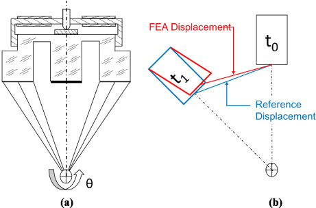
Dynamic analysis definition (a) Model definition (b) Comparison criteria.
Results in Fig. 8 show displacement difference of FEA position from reference position against initial position (shown in Fig. 7(b) with t0). Figure 8(a) shows results of a rotational motion for 0.005 second which is solved using 200-time increments. A section of the results for 0.0012–0.0013 seconds is extracted (shown as dashed) from Fig. 8(a). These results are given on Fig. 8(b). It can be seen that Alternative-1 shows the biggest deflection with 0.697 μm. The usage of second diaphragm for the other designs decrease the total displacement difference. Alternative 2–3 shows 0.275 μm deflection.

Dynamic Analysis Results (a) 0–0,005 seconds (b) 0,0012–0,0013 seconds.
The results of the dynamic analysis show that alternative 2 and 3 has 60% smaller mirror tilt than the first alternative. This reduction of mirror tilt is obtained 38% for alternative 4 and 5 when compared to the first alternative. These results are also investigated with sensor level tests using alternative-1 and alternative-3.
An essential investigation about PLC design is to observe the effects of temperature variations. In the literature, the effect of temperature variations is mainly explained on thermal expansions. The amount of PLC shift to compensate the dimensional variation after thermal expansions is derived analytically. An analytical explanation of this phenomena is given in [9]. The path length L is defined as a multiple of wavelength,
Modification of the path length after thermal variations (ΔT) can be derived using coefficient of thermal expansion (CTE), 𝛼.
However, this thermal expansion induced consideration of dimensional changes is only valid for open systems where the alternation of the pressures is neglected. Another important aspect of the temperature change is the change in pressure difference between the inside and outside pressure (ΔP = P2 − P1). The pressure definition and applied loads are shown on Fig. 9.
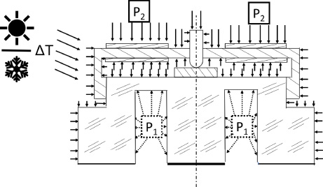
Thermal analysis definition.
As briefly explained in the introduction RLG works with a build-in laser emission which is obtained with the help of a low-pressure gas mixture inside resonator. Gas mixture is excited by electrical potential between cathode and anodes to enforce laser emissions. This pressure difference between low pressure gas mixture inside cavity and atmospheric pressure outside RLG deflects mirrors initially. This phenomenon is experimentally proven for mirrors only under different pressures by the study of Wang et al. (2014) in [30]. Since, commercial RLG sensors usually have a leak tight packaging which acts as a closed system under thermal loading, the pressure outside and inside RLG varies proportional to outside temperature. This variation changes pressure force acting on the PLC and also changes mirror deflections. This study brings a complementary approach for this Multiphysics problem and combines thermal expansions effect with the effect of the pressure force. The variation of the pressure and the effects of thermal expansions for different temperature conditions are simulated using MSC Marc® Thermal/Structural solver. The effects of temperature variations are analyzed for 273, 213 and 353 °K temperature with ∼100,000; ∼72,000; ∼120,000 (Pa) pressure difference consecutively using 3-time steps. Symmetric structure of the PLC designs allows the limitation of the evaluation of thermal analysis results for axial deflections only. Axial deflections are given in Table 4. Deflection values are extracted from the node centered on the reflective surface.
Thermal analysis deflection results
Thermal analysis results regroup 5 PLC designs into 3 group. The first group with maximum deflection values (∼−1,25 μm at 213 °K and ∼−0,64 μm at 353 °K) contains single diaphragm mirror and metal parts (alternative-1). Alternative-2 and -3 create the second group with dual diaphragm and metal parts. Alternative-4 and -5 construct third group with all glass design methodology. The last group has the lowest deflection values for temperature variations; ∼−0,2 μm at 213 °K and ∼−0,3 μm at 353 °K. The reasons behind the reduction of the axial deflection are the increase of the axial stiffness (the rise of the pressure forces is balanced with the rise of the axial stiffness. This increase at axial stiffness is also validated with static structural analysis and mode-scanning tests) and also the lack of metal parts for the last group. Even though the metal parts are manufactured using low CTE alloys, the ratio of the CTE between metals and ULE glass can be up to 500 which results in higher axial deflections under thermal loadings. To validate the Multiphysics problem stated above, a further analysis study is conducted. The model is reconstructed to examine the effects of the thermal expansions alone by excluding the pressure loads. The axial deflections occur to −0.78 μm and 0.15 μm for step 2 and 3 respectively for this loading case. A comparison between Table 4 and these results shows the importance of the pressure on the model. It doubles the deflection value for step 2. Moreover, it is observed that the pressure dominates the effects of the thermal expansions and overwrites the direction of the deflection for step 3. The drastic increase in deflection value for step 3 is reasonable since the temperature change is higher between step 2 and step 3, which also increase the pressure difference proportionally.
RLG sensors are commonly used for aerospace and defense industry as an integral part of the inertial navigation systems. Vibrational responses are important requirement for these application areas. Moreover, lock-in phenomena explained in Dynamic Analysis section showed the importance of dithering for an RLG. Dithering mechanism acts as a mechanical oscillator with given frequency which leads to an investigation of modal responses. It is important to differentiate natural modes of the PLC from RLGs dithering frequency to suppress unwanted resonance conditions. MSC Marc® is used in order to obtain first 6 principal modes (Table 5). Static, thermal and dynamic loads are disregarded for this analysis type. Modal response of the designs shows great correlation with different stiffness and compact design. The rise of the natural frequencies from the first design to last is obtained by the light of these two reasons. Immune designs are obtained against dithering oscillations for modal responses.
Here, principal mode shapes are not shared graphically because the natural frequencies shown on Table 5 are significantly safe when compared to environmental vibrations and dithering motions. However, an important result is observed after the examination of the mode shapes. From alternative-1 to alternative-3, principal mode shapes are highly related to the metal membrane arms and the effect on the mirror is relatively low. The displacement of the mirror reflective surface is prominent in alternative-4 and alternative-5. The natural frequencies are doubled for these two alternatives because the metal membrane is not used, and the designs are more compact. By the help of this increase of the natural frequency, these two alternatives are also found acceptable concerning modal response.
Modal analysis results
Modal analysis results
Although FEA is a powerful tool for concept comparison studies, the verification of the results is needed by tests. Alternative-1 and alternative-3 are selected and produced for verification phase. The verification of the FEA dynamic responses is done indirectly for the two alternatives using the same test bench explained in Fig. 7. Photodetector signal frequency and the amplitudes are given in Table 6.
Dynamic response test results
Dynamic response test results
These photodetector signals are observed under constant dithering motion. It can be seen that the disruptive effects of the dithering motion on the photodetector signal amplitude is reduced from ∼1200 mV (for alternative-1) to ∼210 mV (for alternative-3).
Another investigation is pursued between alternative-1 and alternative-3 using the mode scanning method explained in [11]. Mode scanning test is a method to investigate the axial displacement capability and signal stability of the PLC for a given voltage range. For this study, PZT discs are loaded between 0 to 200 V. Photodetector light intensity is observed. Local maxima of the curves show the integral multiples of the wavelengths. It is observed that the voltage change between local maxima from alternative-1 to alternative-3 increases approximately from ∼50 V to ∼60 V. This validates indirectly the expected increase in axial stiffness of the PLC. FEA results for axial stiffness was obtained for PLC mirror only. This is the reason why the axial stiffness is not doubled as FEA results implies. Mode-scanning results are given in Fig. 10.

Mode-scanning results.
These results of mode-scanning experiments show the variation of axial stiffness. Also, another important observation is made using mode-scanning test for signal stability. The results of alternative-3 for two sensors (/1 and /2) has an offset for light intensity voltages but local maxima are observed at the same PZT voltages with stable form. Voltages and the distance between two maxima are the same for these two sensors (∼60 V). However, the results of sensors using alternative-1 shows a shift for the position of the local maxima between sensors. For alternative-1/1 this shift is so dominant that only 2 maxima can be observed for given PZT voltage range which shows that there is an inconsistency in the design. This problem can be explained by the moment loading characteristics which showed how alternative-1 is sensitive to manufacture and assembly quality. This weakness of mono diaphragm design also showed the importance of the size optimization pursued in the references and also confirmed the reproducibility problems of RLG.
In the light of the analysis results, the main conclusion observed from this study is the existence of divergent characteristics of the different PLC designs. Designer first needs to list the main requirement before starting PLC design, taking into consideration the environmental effects such as thermal and dynamic loadings acting on the INS system. As a conclusion, a summary of how different PLC designs meet the requirements of the environmental conditions is shared below:
Under extreme dynamic conditions such as high acceleration, environmental vibrations and shocks, alternative-2 and alternative-3 creates a preferable option with favorable dynamic conditions. This is provided by the addition of the second diaphragm to the structure which increases the stiffness of the mirror both axially and radially. The mid-section of the mirror acts as a pendulum under dithering vibrations when the second diaphragm is missing. By the addition of the second diaphragm close to the lower end, bending capacity of the mid-section is limited and the disruptive effects of the inertial forces are significantly reduced. The increase of the axial stiffness also reduces the vertical displacement capacity. This is explained as a drawback of this design family which can be compensated at a level by increasing PZT voltage amplitudes. For high temperature variations, as an example for space systems, alternative-4 and alternative-5 come forward with the high temperature stability. This is ensured by the help of the material selection. These designs are all ULE glass designs where the metal membrane, disc and bolt are not in use. Metal parts are used to provide the transfer of the PZT displacement to the mirror. Two drawbacks are observed for all glass designs. These designs have the highest production effort because of the all ULE glass structure. On the other designs, metal parts are adhesively bonded to the mirror. However, for alternative-4 and alternative-5, this is provided by optical contact to improve stability of the bonding interfaces. Optical contact is challenging joining method frequently used for glass-glass assemblies. Compelling production methods are needed to obtain dimensional requirements of this method. The other drawback is the decrease of the system stiffness since the metal parts are replaced by the glass ones having lower structural strength. This is the reason behind that alternative-2 and alternative-3 has better responses to dynamic loads. For wide temperature ranges, Alternative-1 is suggested. Alternative-1 has the lowest axial and radial stiffness. This low stiffness characteristic is a result of the single diaphragm design. Although the low stiffness characteristic looks like a challenging disadvantage, the reduction of axial stiffness let the designer to obtain high amount of modes (local maxima or integral multiple of wavelengths where the output signals are stable and at maximum value) which makes this design favorable for wide temperature ranges in order to prevent mode resets. For most of the RLGs, mode-reset is a procedure used by the PLC controller to reinitialize the PZT voltage. When the sensor works under wide temperature ranges, the upper limit voltage of the PZT could be reached (200 V for the current mode-scan test). When this condition occurs, PLC controller reduces the voltage to 0 and reinitialize the PLC. The time elapsed for the mode-reset procedure results in the reduction of the sensor sensitivity. However, in case alternative-1 is used, high manufacturing and assembly quality is needed. As explained in the second chapter, the moment load is used to simulate manufacturing defects where alternative-1 shows the lack of immunity for small manufacture and assembly failures. This is also observed indirectly with the shift on the mode-scanning test between two alternative-1 PLC used sensors.
Conflicts of interest
The authors declare no conflict of interest.