
Abstract
This paper investigates the magnetic circuit model of a multi-pole multi-layer magnetorheological (MR) brake. Firstly, a simple introduction to the structure is given. This MR brake has a unique structure design with several MR fluid working gaps set between two-layer coils. Then, magnetic circuit model is conducted to theoretically approximate the effects of the design parameters on the magnetic field strength within the MR fluids. According to the magnetic circuit analysis, a parametric study is performed to optimize the critical design parameters of the magnetic circuit of the designed brake. Finally, the magnetic circuit model is validated based on the optimized structure and simulation. Simulation results indicate that the magnetic circuit model is feasible to estimate the magnetic field strength in the working gaps, and it can be used to guide the parameters optimization and structure design.
Introduction
It is well known that magnetorheological (MR) fluid is a smart material which can be widely used as application actuators [1], such as dampers [2,3], brakes [4–7], clutches [8–10], shock absorber [11], mount [12], valves [13], and so on. Those actuators have many advantages including fast and reversible property between liquid phase and semi-solid state, low power consumption, smoothness, safety of operation and high torque density. Generally, MR fluid is often operated in four main modes: direct shear mode, valve mode, squeeze mode and pinch mode.
MR brake is operated in direct shear mode, and the MR fluid is contained between two parallel/concentric surfaces when an external magnetic field is applied to the fluid. A surface moves or rotates relative to another surface which shears the fluid layer directly. Thus, the shear resistance is produced and the magnitude of force depends on the intensity of the applied magnetic field. More recently, MR brake is one of the widely studied braking devices that have many advantages than traditional frictional one, with simple control system, high safety and little wear.
To date, many research works have been carried out on MR brakes, including the conceptual design, the theoretical or analytical models, experiments on concept verification, and develop MR brake for practical realization. In the review, MR brake was classified into three types according to MR fluid gap form, disc type, cylindrical type, and hybrid type. For instance, Song et al. [14] proposed a disc-type MR brake adjustable gap. Wang et al. [15] studied the effect of surface texture and working gap on the braking performance of the magnetorheological fluid brake. Sarkar et al. [16] developed a disc-type MR brake that operating under compression plus shear mode of MR fluid. Rossa et al. [17] studied a concentric cylinder-brake. Qin et al. [4] designed a small-scale multi-drum yet powerful MR brake. Shiao et al. [18] presented a multi-pole MR brake. Shiao et al. [19] also presented a multi-pole bilayer MR brake with a higher torque density. Wu et al. [20] proposed a multi-pole and dual-gap MR brake with individual currents. Senkal et al. [21] designed a MR brake with a serpentine flux path. Rossa et al. [22] discussed the torque density, efficiency, bandwidth and controllability of different MR brakes, including a single disc brake, a single drum brake, multiple-disc based brakes and multiple-cylinder based brakes.
The researchers pay more attention to the structural innovation design on the performance improvements of high braking torque, but there is little study on the magnetic circuit. Nguyen et al. [23] proposed a new approach to magnetic circuit model for a bi-directional MR brake and applied it to explore an engineering optimization problem. Shamieh et al. [24] presented a magnetic circuit analysis of a disk-type MRB to derive the relation between magnetic field intensity and the applied electrical current, geometrical and material properties. Shiao et al. [18] proposed and analyzed the magnetic circuit of a multi-pole MR brake based on Ampere’s law and Gauss’s law. The author has designed and tested a novel radial multi-pole multi-layer MR brake [5], but the magnetic circuit has not been evaluated.
In this paper, magnetic circuit modeling, design optimization and finite element analysis of a new multi-pole multi-layer MR brake were carried out. Section 1 introduces the study on MR brake. Section 2 details a brake design with several coils. Section 3 develops a magnetic circuit model to investigate the effects of the design parameters on the magnetic field strength within the MR fluid. Section 4 optimizes the important parameters of the brake design by simulation. Section 5 discusses simulation and calculation results, and Section 6 concludes this study.
Structure description
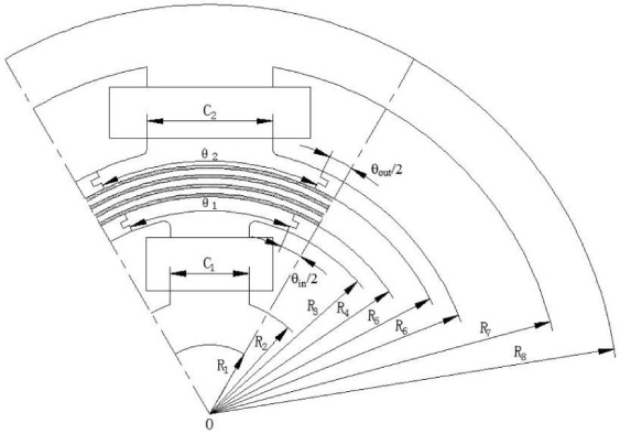
The author has designed a new multi-pole multi-layer MR brake [5], as shown in Fig. 1. The proposed MR brake is based on the superposition principle of two magnetic fields generated by the inner coils and the outer coils. It contains an inner stator assembly with six electromagnetic poles with winding coils, an outer stator assembly with six electromagnetic poles with winding coils, Cylinder A, Cylinder B, Cylinder C, and four MR fluid layers located between the hat of the inner stator and the shoe of the outer stator. Cylinder A and Cylinder C are connected to the rotary shaft, while the Cylinder B is connected to the stationary housing as well as the inner stator assembly and the outer stator assembly. Two adjacent electromagnetic poles of inner/outer stators are connected by aluminum plate in order to make the produced magnetic flux penetrates MR fluid working gaps. The direction of magnetic flux in each pole of the inner/outer stator is opposite to that of its two adjacent poles, while the direction of magnetic flux in the pole of the inner stator is the same as that of the pole of the outer stator when the two poles are in the same radial direction. The MR fluid contained in the four working gap is subject to shear due to slippage between the MR fluid and each cylinder as a resistance source for the brake. It should be noted that the thicknesses of the four working gaps are set to be equal, and the three cylinders have an equal thickness, in our study. In addition, low carbon steel, 20# was selected as the magnetic material in the magnetic circuit (i.e. the inner stator assembly, outer stator assembly, Cylinder A, Cylinder B and Cylinder C). Considering the processing performance and magnetic isolation performance, aluminums alloy is selected as the material of aluminum plates, and stainless steel 304# was selected as a material for non-magnetic circuit parts.
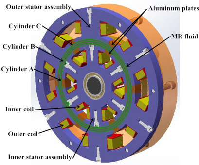
Structural schematic diagram of a new multi-pole multi-layer MR brake.
The magnetic circuit analysis of the proposed MR brake is a complex 3D problem. In order to simplify the calculation of magnetic circuit, it is assumed that the air boundary around the enclosure is infinite, the magnetic flux leakage in the surrounding air can be neglected, all magnetic lines are confined inside the device, the parts of the brake are closely coupled to ignore the flux leakage of the components in the magnetic circuit part, the permeability of the materials in the magnetic circuit is constant as well as the MR fluid in the working gaps, and the influence of temperature on the physical properties of parts of the device is neglected.
Due to that the proposed MR brake has a symmetrical structure with twelve electromagnetic poles with winding coils, the magnetic field of only four adjacent poles (two adjacent inner coils and two adjacent outer coils) are analyzed when all the excitation coils are energized. The magnetic circuit model mainly consists of two magnetic poles with inner coils, two magnetic poles with outer coils, four MR fluid layers, Cylinder A, Cylinder B, Cylinder C, and the aluminum plates. In our design, the turns of the outer coils are more than that of the inner coils and the applied currents to the inner and outer coils are equal. Figure 2 shows the detailed illustration of the magnetic flux between four adjacent poles when the current applied to all coils increases from 0.5 to 2.0 A with steps of 0.5 A. Figure 3 shows the magnetic flux density of MR fluid gaps in the circumferential direction. The positions of the space between poles are indicated by the six peaks in the figure. According to the above figures, the magnetic circuit of the designed brake was divided into three parts: one main magnetic circuit (solid line) and three branch magnetic circuits (dotted line), as shown in Fig. 4. The main magnetic circuit is the loop formed between four adjacent magnetic poles (two adjacent inner coils and two adjacent outer coils), which is the effective magnetic circuit expected by the magnetic circuit design of the MR brake. The branch magnetic circuits are composed of three parts: one inner magnetic circuit and two outer magnetic circuits, and is formed between two adjacent inner coils or two adjacent outer coils.
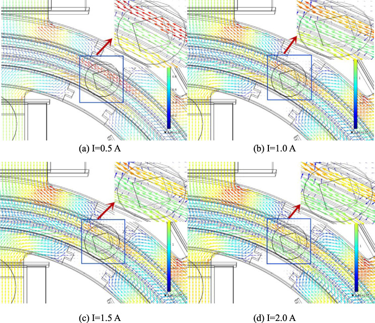
Detailed illustration of the magnetic flux between four adjacent poles.

Circumferential magnetic flux density in MR fluid gaps: (a) gap II; (b) gap III.
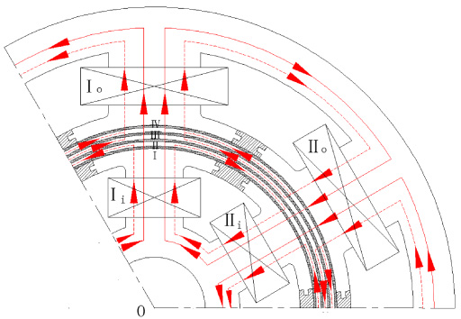
Magnetic circuit of the multi-pole multi-layer MR brake.

Node configuration of the multi-pole multi-layer MR brake.
Due to that the section areas and the materials of each part of the magnetic circuit are different, so does the magnetic field strength. Thus, the whole magnetic circuit is divided into the following sections according to the field strength, as shown in Fig. 5.
a 1 b 1, a 2 b 2—Shoe of the inner stator.
b 1 c 1, b 2 c 2—Hat of the inner stator.
c 1 d 1, c 2 d 2—MR fluid gap I.
d 1 e 1, d 2 e 2—Cylinder A along the main magnetic circuit.
e 1 f 1, e 2 f 2—MR fluid gap II.
f 1 g 1, f 2 g 2—Cylinder B along the main magnetic circuit.
g 1 h 1, g 2 h 2—MR fluid gap III.
h 1 i 1, h 2 i 2—Cylinder C along the main magnetic circuit.
i 1 j 1, i 2 j 2—MR fluid gap IV.
j 1 k 1, j 2 k 2—Shoe of the outer stator.
k 1 m 1, k 2 m 2—Hat of the outer stator.
a 1 a 2—Inner stator ring.
m 1 m 2—Outer stator ring.
d 1 d 2—Cylinder A along the branch magnetic circuit.
g 1 g 2—Cylinder B along the branch magnetic circuit.
i 1 i 2—Cylinder C along the branch magnetic circuit.
Figure 6 shows the equivalent magnetic circuit of the multi-pole multi-layer MR brake. R
si
, R
iu
and R
id
are the reluctances of the inner stator ring, the hat of the inner stator, the shoe of the inner stator, respectively. R
m1, R
m2, R
m3 and R
m4 are the reluctances of gap I, gap II, gap III, gap IV, respectively. R
r1, R
r2 and R
r3 are the reluctances of Cylinder A, Cylinder B, Cylinder C, along the main magnetic circuit, respectively.
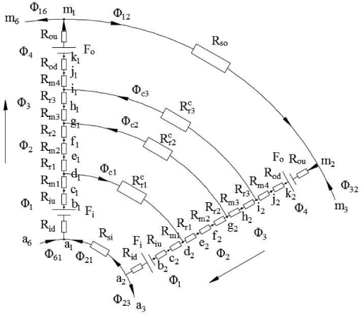
Equivalent magnetic circuit of the multi-pole multi-layer MR brake.
Definitions of design parameters.
The major design parameters are also defined as shown in Fig. 7. The brake is composed of four fluid gaps. We denote by C 1 the inner stator width, C 2 the outer stator width, θ1 the inner stator angle, θ2 the outer stator angle, R 1 and R 4 the inner radius and the outer radius of the inner stator respectively, R 2 and R 3 the shoe radius and the hat radius of the inner stator respectively, R 5 and R 8 the inner radius and the outer radius of the outer stator respectively, R 6 and R 7 the shoe radius and the hat radius of the outer stator respectively. Table 1 lists the key design parameters of the designed MR brake.
Key design parameters overview of the designed MR brake
The magnetic reluctance of different sections can be obtained by Ohm’s Law of magnetic circuit [25], as given by the following equation:
For the magnetic reluctances of the inner stator hat, outer stator shoe, four MR fluid gaps and three cylindrical shells, the calculation method of the magnetic reluctance between two coaxial cylinders can be used
When the inner and the outer coils are applied with individual input currents, respectively, the magnetic flux which travels through the inner coil I
i is equal to that of the inner coil II
i. According to the law of magnetic flux continuity and the symmetry of the proposed MR brake structure:
The relationship between magnetic field strength H and corresponding magnetic flux density B is
The integration of this magnetic flux density over the cross-sectional area A of the core yields the magnetic flux 𝛷 as following
The magnetic reluctance R
mi
of the MR fluid within four working gaps can be calculated as
Assuming that 𝛷
c1 = 𝜆1𝛷1 ≤ B
s
S
r1, substituting equations (4) and (12) into (9), then
After substituting equation ((1)), ((2)), ((14)) into ((15)), the magnetic field strength of the MR fluid gap I H
m1 can be obtained by
Assuming that 𝛷
c3 = 𝜆3𝛷4 ≤ B
s
S
r3, 𝜆3 is the relevant coefficient, S
r3 is the cross-sectional area of Cylinder C which is perpendicular to the branch magnetic circuit, substituting equations ((4)) and ((12)) into ((11)), then
Substituting equation ((12)) into 𝛷
c3 = 𝜆3𝛷4, then
Simplifying equation (12), then
According to (16), (18), (21), and (24), the magnetic field strength in four MR fluid gaps could be obtained. In general, the effects of the structure parameters, the magnetomotive forces, the magnetic properties of the magnetic materials, MR fluid properties on the magnetic field strength within the MR fluid working gaps can be computed, and the main factors to further guide the design and optimization of the MR brake structure could be obtained.
This section deals with a parametric study of the proposed MR brake based on the magnetic circuit analysis above. The primary goal of this parametric study is to show how the critical design parameters (design dimensions and magnetomotive forces) affect the performance of the proposed MR brake. In particular, the structure parameters as well as the magnetomotive forces to magnetic field strength within four fluid gaps are investigated because the gap magnetic field strength directly determines the output braking torque. It should be noted that only the parts of the magnetic circuit, that is, six inner stators, six outer stators, three cylinders and four MR fluid gaps, are taken into consideration.
Effect of MR fluid gap
The generated braking torque basically depends on the magnetic field strength in four MR fluid gaps. Four probe lines were drawn along the circumference and in the middle of these four gaps. Figure 8 shows the simulated values of magnetic flux density in the four working gaps when the gap thickness increases from 0.5 to 2.0 mm with steps of 0.5 mm, and the current applied to all coils is 1.0 A. It should be noted that the 0 degrees in Fig. 8 start from the middle of these four gaps between the two adjacent inner/outer stators (that is, under the aluminum plates). It can be seen from the figure that the magnetic flux density decreases with the increase of the gap thickness. The maximum magnetic flux densities within the gap I, gap II, gap III, gap IV are 0.72 T, 0.61 T, 0.68 T, and 0.82 T, respectively, when the gap thickness is minimum value and it occurred in pole-head area due to its thinness. When the gap thickness increases from 0.5 to 2.0 mm, the flux densities decrease 42%, 49%, 46%, 44%, respectively. However, smaller gap will lead to the difficulty of the flow of MR fluid in the gaps, and it will also make higher requirements for processing and assembly. In summary, the thickness of four gaps is set as 1.0 mm.
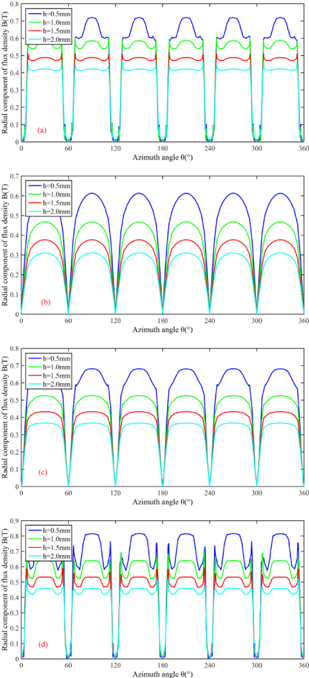
Magnetic flux density in MR fluid gaps: (a) gap I; (b) gap II; (c) gap III; (d) gap IV, for different gap thicknesses.
From the previous magnetic circuit model, it can be seen that the thicknesses of cylinders A, B and C have an important influence on the magnetic flux of three branch magnetic circuits, so it is necessary to analyze the thickness of all cylinders. Figure 9 shows the distribution of magnetic field lines on the three cylinders when the thickness of three cylinders increases from 1.0 to 4.0 mm, and the current applied to all coils is 1.0 A. It can be seen from the figure that:
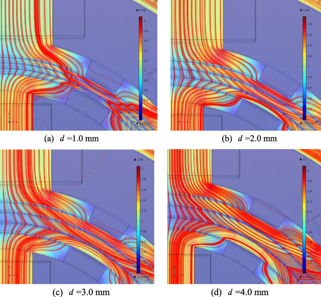
Magnetic flux densities in three cylinders.
(1) According to Figs 2 and 9, about 90% of the magnetic flux will orthogonally penetrate the MR fluid in four working gaps. The smaller the thickness of three cylinders is, the higher radial magnetic flux is. However, too small thickness leads to insufficient strength, and it will also bring difficulties in processing and manufacturing.
(2) The bigger the thickness of three cylinders is, the more the magnetic flux passing through Cylinder A, Cylinder B and Cylinder C along the three branch magnetic circuits are. Therefore, the thickness of the three cylinders should be smaller as far as possible.
Figure 10 shows the magnetic flux density in the four working gaps at different cylinder thicknesses (1.0 mm, 2.0 mm, 3.0 mm and 4.0 mm), and the current applied to all coils is 1.0 A. It should be noted that the 0 degrees start from the middle of these four gaps between the two adjacent inner/outer stators (that is, under the aluminum plates). It can be seen from the figure that:
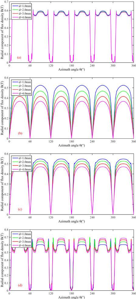
Magnetic flux density in MR fluid gaps: (a) gap I; (b) gap II; (c) gap III; (d) gap IV, for different cylinder thicknesses.
(1) The magnetic flux density in gap I is not affected by the thickness of three cylinders, so it indicates that the magnetic flux through gap I is constant when the magnetomotive forces and other structure parameters are determined.
(2) The magnetic flux densities in gap II and III decrease with the increase of the thickness of three cylinders. When the thickness value of three cylinder increases from 1.0 to 4.0 mm, the magnetic flux density in gap II decreases by about 30% and that in gap III decreases by about 15%. The result also shows that more magnetic flux will travel along the circumferential direction of three cylinders with the increase of the thickness of three cylinders.
(3) The magnetic flux density in gap IV increases with the increase of the thickness of three cylinders. When the thickness value of three cylinders increases from 1.0 to 4.0 mm, the magnetic flux density in gap IV increases by about 14%. The outer stator reaches to be saturated later than the inner stator. When the thickness of three cylinders increases, the magnetic flux flowing along the circumferential direction of Cylinder C will increase, so does the flux in the gap IV.
From the above analysis, it can be seen that the effect of the thickness of three cylinders on the flux density in the gaps is obvious. By considering the factors of processing, manufacturing and the strength of parts, the thickness of three cylinders is set as 2.0 mm.
In order to achieve that most of the produced magnetic flux orthogonally penetrate the MR fluid in the working gaps along the main magnetic circuit, several aluminum plates are set between two adjacent inner/outer stators. The aluminum plates have an important influence on the magnetic field strength in MR fluid gaps, as shown in Section 3. From equation (16), the smaller the magnetic field strength of the MR fluid gap I H m1 is, the bigger the angle value θ1 is. From equation (18), the smaller the magnetic field strength of the MR fluid gap IV H m4 is, the bigger the angle value θ2 is. Equations (21) and (24) also shows the relationship between the magnetic field strength of the MR fluid gaps II, III and the angle values θ1, θ2, but the influence is not directly perceived through the equations. Then, the circumferential angles of the aluminum plates θ in and θ out are analyzed. According to the structural parameters shown in Fig. 7, the following relationships are established: θ in = 60° − θ1; θ out = 60° − θ2.
Only changing the circumferential width of the aluminum plate θ in while the other parameters keep fixed, and observing the changes of magnetic flux density in the four gapes. Assuming that the current applied to all inner and outer coils is 1.0 A, and the solution interval of θ in is 8° ∼ 20° while the solution step size is 6°. Figure 11 shows the magnetic flux density within the four gaps when the angle θ in is 8°, 14° and 20°, respectively. It should be noted that the 0 degrees start from the middle of these four gaps between the two adjacent inner/outer stators (that is, under the aluminum plates). It can be seen from the figure that:
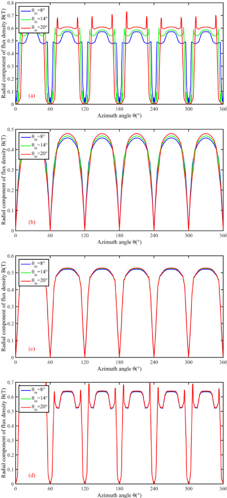
Magnetic flux density in MR fluid gaps: (a) gap I; (b) gap II; (c) gap III; (d) gap IV, for different aluminum plate angle θ in .
(1) The flux densities in gap II, III and IV are not affected by the angle θ in .
(2) With the increase of the angle θ in , the magnetic flux density in the gap I increases, but the effective width (peak width) of the magnetic flux density decreases. Therefore, the influence of the angle θ in on the performance of the brake needs to be further judged according to the braking torque.
Only changing the circumferential width of the aluminum plate θ out while the other parameters keep fixed, and observing the changes of magnetic flux density in the four gapes. Assuming that the current applied to all inner and outer coils is 1.0 A, and the solution interval of θ out is 6° ∼ 22° while the solution step size is 8°. Figure 12 shows the magnetic flux density within the four gaps when the angle θ out is 6°, 14° and 22°, respectively, and the current applied to all coils is 1.0 A. It should be noted that the 0 degrees start from the middle of these four gaps between the two adjacent inner/outer stators (that is, under the aluminum plates). It can be seen from the figure that:
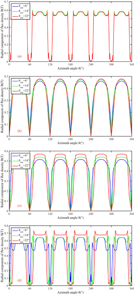
Magnetic flux density in MR fluid gaps: (a) gap I; (b) gap II; (c) gap III; (d) gap IV, for different aluminum plate angle θ out .
(1) The magnetic flux densities in gap I and II are not affected by the angle θ out .
(2) With the increase of the angle θ in , the magnetic flux densities in gap III and gap IV increase, but the effective width (peak width) of the magnetic flux density decreases. Therefore, the influence of the angle θ in on the performance of the brake needs to be further judged according to the braking torque.
Generally speaking, the angles θ in and θ out should be considered comprehensively in the design. In this study, BOBYQA optimization method is used to optimize the two parameters. The optimization results are rounded: θ in = 14°, θ out = 10°.
Due to that the magnetomotive forces of the magnetic circuit of the MR brake designed in this paper are provided by six inner coils and six outer coils, the magnetomotive forces need to be allocated. According to the design requirements, we calculated that the total magnetomotive force is 1100 A-turns, and the maximum current is set as 2.0 A. Thus, the total turns of one inner coil and one outer coil are 550 turns.
Figure 13 shows the magnetic flux density in four gaps when the turns of one inner coil are from 100 to 300 turns with a step of 50 turns and the turns of one outer coil are from 450 to 250 turns with a step of −50 turns. It should be noted that the 0 degrees start from the middle of these four gaps between the two adjacent inner/outer stators (that is, under the aluminum plates). It can be seen from the figure that the magnetic flux density in gap I increases and the magnetic flux densities in gap II, gap III and gap IV decreases gradually, with increasing the turns of inner coil. This shows that the turns of inner coil mainly affects the magnetic flux density in gap I, while the turns of outer coil mainly affects the magnetic flux densities in gap II, gap III and gap IV.
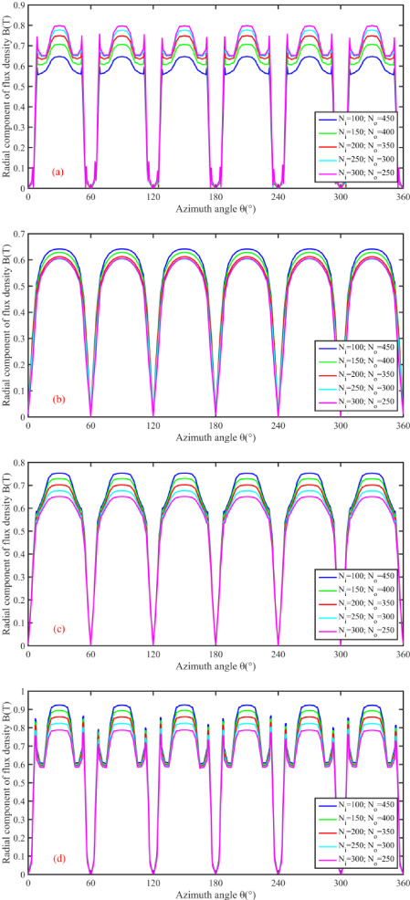
Magnetic flux density in MR fluid gaps: (a) gap I; (b) gap II; (c) gap III; (d) gap IV, for different coil turns.
It is necessary to consider both coil space and magnetic circuit comprehensively. In our design, the number of inner coil is set as 200 turns, and that of outer coil is set as 350 turns. In summary, the main parameters of the proposed MR brake are obtained as given in previous work [5].
Three-dimensional solid model of the designed MR brake is established based on the data from paper [5]. Then, finite element analysis of the brake was carried out to obtain the magnetic field strength in the working gaps and calculate the main parameters of the deigned magnetic circuit. The Lord MRF-132DG MR fluid [26] and the low-carbon steel [27] are nonlinear ferromagnetic materials, whose material properties are defined by the B-H curves, while the relative permeability of the non-ferromagnetic materials, including stainless steel, aluminum and air, were all set as 1. The magnetomotive force of each inner/outer coil was defined by coil turns and coil current. It should be noted that the input current in each coil is limited to 2.0 A for avoiding saturation. Figure 14 shows the magnetic flux density in the cross-section of the designed MR brake. The magnetic flux density within four MR fluid gaps of the areas shown in Fig. 14(b) was used to evaluate the field strength of the four gaps.
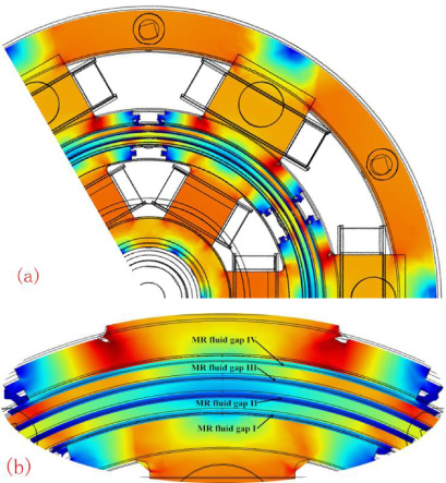
Magnetic flux density in the cross-section of the designed MR brake: (a) one-third of the designed brake; (b) expanded view of magnetic flux density in four gaps.
Table 2 shows the simulated stable values of magnetic field strength in the four gaps near the six inner/outer stators (the areas shown in Fig. 14(b)). The magnetic field strength within four gaps increases with the increases of the input current. In addition, the increase rate of the magnetic field strength in gap I, II, and III slows down gradually. This is because that the width of the inner stator is limited, and the inner stator becomes be saturated earlier than the outer stator.
Simulated values of magnetic field strength in the four gaps near the inner/outer stators
The values of parameters (𝜆1, 𝜆2, 𝜆3) are unknown from above magnetic circuit analysis, while these are key factors in calculating magnetic field strength within the MR fluid gaps. In view of this, the magnetic field strengths in gap I, gap II, and gap III were obtained by finite element analysis firstly when the input current increases from 0.2 to 2.0 A with a step of 0.2 A. Then, the values of the three parameters could be obtained at these calculation points. Furthermore, the calculated values of the parameters can be approximated in terms of a function of the input current applied to the coils by using a curve-fitting method, as shown in equation (25). Thus, the magnetic field strength within the four MR fluid gaps could be obtained by equations (16), (18), (21) and (24).
In this section, the goal is to determine the errors between simulation results and calculation results over the gaps. The coil current was increased from 0.3 A to 1.8 A with a step of 0.3 A. The simulated results are determined by the stable values of magnetic field strength in the gaps near the six inner/outer stators (the areas shown in Fig. 14(b)). Figure 15 shows the relationship between input current and magnetic field strength within the gaps (gap I, III, and IV) based on the magnetic circuit model and the finite element simulation. As shown in the figure, the simulated data were very close to the data calculated by the finite element analysis. The difference between simulated and calculated values of H m1 and H m4 is less than 6%. In these two gaps, the maximum error happened at 1.8 A. At this point, the measured and derived magnetic field strengths were 132.1 and 124 kA/m, respectively, giving the error of 8.1 kA/m. The difference between simulated and calculated values of H m3 increases first and then decreases when the current varies from 0.9 to 1.5 A. In this gap, the maximum error happened at 1.2 A and the error is 37.8%. The result indicates that the magnetic circuit model is feasible to analyze the influence of structural parameters on magnetic field strength in the working gaps. Figure 16 shows the simulated and calculated field strength of gap II. As can be seen from the figure, the 0.3 times of the calculated value is in good agreement with the simulation value when the input current is no more than 0.9 A. When the current continues to increase from 0.9 to 1.2 A, the error increases gradually. The maximum error is 56.2% at 1.2 A current input. This happened because the effect of magnetic circuit simplification on magnetic field strength of gap II is great and the accuracy of the model is not enough.
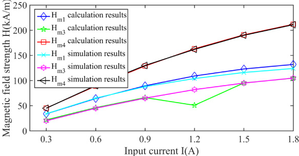
Magnetic field strength calculated and simulated over three gaps (gap I, III, and IV).
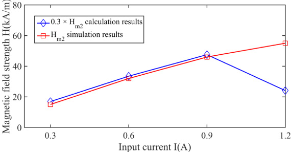
Magnetic field strength calculated and simulated over gap II.
Generally speaking, the use of the magnetic circuit model proposed in this study needs to be combined with the simulation, and the errors are relatively large, especially the gap II. Future work should focus on further improving the magnetic circuit model.
In this paper, a new multi-pole multi-layer MR brake was further studied and subjected to magnetic circuit modeling, design optimization and magnetic simulation. A magnetic circuit model was established to investigate the effects of the design parameters on the magnetic field strength within the MR fluid. According to the magnetic circuit analysis, the gap thickness, three cylinders thickness, aluminum plate dimension and the magnetomotive forces of the magnetic circuit were optimized using a parametric study. According to the optimized structure, the calculation formula of magnetic field strength was carried out by the simulation and the magnetic circuit model. The results show that the calculated results of magnetic circuit model are in good agreement with the simulation for gap I, III, and IV, while the error to gap II is much bigger. In general, it can provide guidance for future design and optimization.
Footnotes
Acknowledgements
This work was supported by the National Natural Science Foundation of China (Grant No. 51805444). This work was also supported by the Young Scholars Reserve Talents Support Program of Xihua University, the Xihua University (Z1220219) and the National Key Research and Development Plan (2016YFD0700400). In addition, we thank the support from Xi Xie.