
Abstract
Magnetic levitation is state-of-the-art technology to realize 6 degree of freedom motion stages. The major weakness of magnetic levitation technology is the small force of the actuators, since electromagnetic actuators usually have small force compared to other actuators. Moreover, they always have to be turned on in order to compensate for the weight of the stage. In this paper, voice coil motors, a kind of electromagnetic actuator, are designed for a magnetic levitation stage. Two different types of voice coil motors are mathematically modeled, analyzed and optimized to obtain high force. According to the optimized final designs, the voice coil motors are manufactured and their performances are evaluated. The optimal design results are compared with the finite element simulations and the test results of the manufactured products. Both types of voice coil motors show high force. The results are quantified and compared. Through the design process and the evaluation of the voice coil motors, a practical design guideline for a voice coil motor is suggested.
Introduction
There are many types of mechanisms to realize fast and precision motion stages. One kind of mechanism, magnetic levitation (Maglev), has been widely researched over the last three decades [1–8], and now is state-of-the-art technology to actuate and guide a 6 degree-of-freedom (DOF) precision stage. A maglev stage is levitated by several electromagnetic actuators. Those actuators are also used to move the stage in the horizontal plane, keeping the orientation of the stage unchanged. That actuating and guiding principle leads to fast response and high precision of motion, since the moving platforms of maglev stages have very simple structures and very light weight, whereas the moving platforms of conventional stages have bulky structures and heavy weight [9]. Because they employ piezoelectric actuators, conventional stages have complex structures. Small deformation of piezoelectric material introduces a bulky motion amplifier. Moreover, a complex guidance system is required to impose restoring force because only the elongation of the piezoelectric material can be utilized [10,11]. Conventional stages with electromagnetic actuators and air bearing guides have a non-contact characteristic, leading to high precision of motion. However an air supply/spurt system makes the structure bulky and inefficient when multiple DOF motion is realized [12]. In the case of a maglev stage, however, the moving platform consists only of movers of electromagnetic actuators and a panel on which a specimen is placed. The simple and light structure gives the maglev stage benefits of fast response, high control stiffness and, accordingly, high precision of motion [9].
However, the maglev stage suffers from large burden on the actuators because the weight of the levitated moving platform should be supported. Therefore, high force density of the electromagnetic actuator is strongly required. Kim et al. have developed two different types of voice coil motors (VCMs) using permanent magnets and coils [3–6]. Magnetic flux of a permanent magnet flows out from the N pole and into the S pole. In order to make an area have strong magnetic flux density, the flux is manipulated by an arrangement of magnets or an additional magnetically soft material such as a steel bar. But Kim et al. used permanent magnets in an open space, so that the magnetic flux density was very low and thus the generated forces were also small. If large force is to be acquired, heat generation due to high current would become a serious problem. Gao et al. developed a VCM of circular shape. They used a repulsive magnet pair and magnetically soft material for the magnetizer and the yoke to make a closed-loop of magnetic flux [13]. Another VCM structure was developed by Zhang and Menq [7]. Two magnets and a steel frame were utilized to make strong magnetic flux density in the air gap. Two coils for vertical motion and another coil for horizontal motion share one magnetic flux path. It seems that the two actuators are configured in one compact unit, but it is not really effective. Magnetic flux could be stronger than one magnet configuration in open space, but the large air gap due to the two coils diminishes the magnetic flux density. Furthermore, more than the half of the coils is not used to generate force because it is outside of the flux concentrated area. A VCM with double sided magnet pairs was designed by Hollis et al. [1]. The air gap between magnets is filled with uniform and strong magnetic flux of which half has a direction opposite to that of the other half. Since the magnetic flux density is very high due to small air gap and the whole coil except the rounded part is used to generate force, the VCM is able to achieve high force density. A different type of VCM was developed by Choi et al. [14]. It has four single sided magnet pairs attached to the outer back-yoke to make high and uniform magnetic flux at the air gap formed by the inner yoke of a square column. The whole volume of the coil interacts with the magnetic field, and the VCM generates very high force.
In this paper, two types of VCMs are developed for a maglev stage. One type of VCM has the typical structure of Hollis and drives the stage in the XY plane, which is perpendicular to the direction of gravity. The other type of VCM has the structure designed by Choi, drive the stage along the z direction which is parallel to the direction of the gravity. Both types of VCMs are proposed, modeled, optimally designed and tested. For the detailed description, a brief introduction of the maglev stage and conceptual designs of VCMs are presented in Section 2. Magnetic, electric and mechanical modeling of VCMs are proposed in Section 3 and the optimal design process is described in Section 4. The optimized VCMs are manufactured and evaluated in Section 5. A design guide for a VCM based on the design procedure is presented in Section 6; Section 7 is the conclusion.
Maglev stage and VCM
As described in Section 1, the maglev stage has a very simple structure as shown in Fig. 1(A). The moving platform is levitated and driven by the VCMs on the base frame. The desired motion of the moving platform is scanning or stepping in the XY plane while keeping the initial position in the other directions. Therefore, eight VCMs are arranged as shown in Fig. 1(B) and they generate force to make 6 DOF motion of the moving platform. Four VCMs for Horizontal Motions (HVCM) are placed along the edges to drive in-plane motion (XY𝛩 z ) and the other four VCMs for Vertical Motions (VVCM) are placed at the corners to drive out-of-plane motion (Z𝛩 x 𝛩 y ). Separation of the role of the VCMs makes the control algorithm simple and helps to decide target specifications of the VCMs through the design process. The symmetric arrangement of the VCMs yields simple kinematics, and accordingly a simple design process. The magnets of the VCMs are movers attached to the moving platform and the coils of the VCMs are stators attached to the base frame, as heat generated from the coils is not directly transmitted to the moving platform or accordingly to the specimen. Moreover, the moving magnet - static coil structure is free from wire disturbance, wire wear, and risk of wire disconnection by repeated motion.
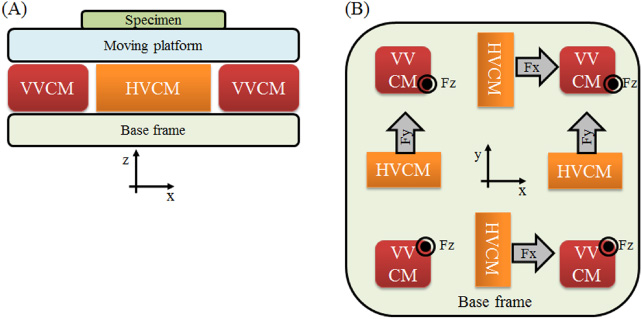
(A) Simplified scheme of maglev stage. (B) Arrangement of eight VCMs. HVCM generates horizontal force and VVCM generates vertical force. The moving platform and the specimen are omitted in (B).
The target performances and some dimensions of the maglev stage are shown in Table 1. The maglev stage is a part of the pilot product purposing lithography process of 200 mm size wafer. The VCMs are designed to satisfy the target performance within the confined volume. The given boundary conditions for the VCMs are presented in Table 2. Milestones for the design of the VCMs are as follows.
Large force
Generation of large force is advantageous to achieve not only the specified acceleration, but also fast dynamic response. Thus it is important to obtain large force with size limitation.
Uniform characteristic
The main characteristic of the VCM is the relation between the generated force and the provided current. This is expressed as the term “force constant”, which should be uniform even though the platform moves. The uniformity makes control easy.
Leak-proof magnetic flux path
A steel yoke is utilized to make a magnetic flux path to enhance the magnetic flux density at the air gap. If the yoke is magnetically saturated, a significant amount of magnetic flux leaks out of the intended path, which can be very harmful to other actuators or nearby specimens.
Small heat generation
The VCM, a kind of electromagnetic actuator, changes electric energy to mechanical energy. In that process, a significant amount of electric energy is dissipated as heat, causing temperature increase of coils, magnets and other nearby components. The effort required to lower the temperatures below a safety level is lessened if the heat generation is small.
Target performances and dimensions of maglev stage
Boundary conditions for VCMs
According to the design milestones, two different types of VCMs are proposed for the maglev stage. A conceptual drawing of the HVCM is shown in Fig. 2. It has a typical structure that have been widely used, but shows high and uniform magnetic flux density formed by double sided magnet pairs and back yokes [1]. Lorentz force is generated along the horizontal direction when electric current passes through the coil. The HVCM can be expanded horizontally, not vertically, for large force. Thus, the small aspect ratio of the structure is favorable for the space limitations given in Table 2. Force enhancement by vertical expansion has a limitation because magnetic flux, after a certain level, barely increases when the thickness of the magnet increases. An increase in the number of turns of the coils can be another option, but this causes a large air gap, and accordingly diminishes magnetic flux density.
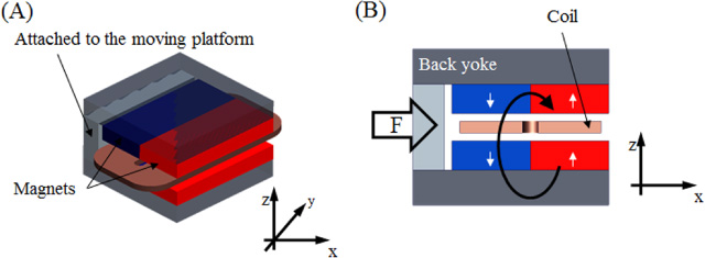
(A) Conceptual design of HVCM. (B) Cross-sectional view of HVCM. The white arrows designate the magnetization direction of the magnets and the black arrow designates the magnetic flux path. The arrow with ‘F’ designates the direction of the generated force.
A conceptual drawing of the VVCM is shown in Fig. 3. It has four single sided magnet pairs attached to the outer back-yoke. The inner yoke should be large enough to avoid magnetic saturation. The upper coil and the lower coil are wound in different directions to generate force along the same direction. The whole volume of the VVCM coil interacts with the magnetic field, whereas only a portion of the HVCM coil interacts with the magnetic field. This feature gives the VVCM high force with small volume. The VVCM can be expanded vertically, not horizontally, for large force. Thus, the high aspect ratio is favorable for the size limitations given in Table 2. The horizontal expansion induces an increase of the magnet thickness or the number of coil turns. Both options have limitations for force enhancement for the same reasons as HVCM.

(A) Conceptual design of VVCM. (B) Cross-sectional view of VVCM. The white arrows designate the magnetization direction of the magnets and the black arrows designate the magnetic flux paths. The arrow with ‘F’ designates the direction of the generated force.
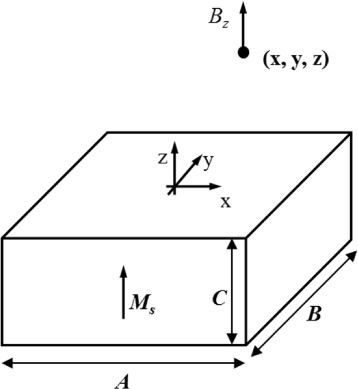
Cuboidal magnet in free space.
Background theory
Based on the conceptual design of the VCMs, an analytic model is established. For both VCMs, magnetic flux density at the air gap where the coils are placed is mathematically derived from the Maxwell equation. The charge model [15,16], which is known to be very accurate, regards a magnet as a distribution of magnetic charges. A magnetostatic field established by a permanent magnet in free space is given by Eqs ((1))–((3)) referring to Fulani’s work [15].
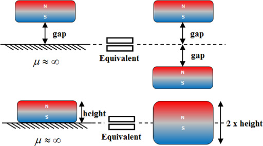
Application examples of image method.
Based on the mathematical model of the magnetic flux density, the Lorentz force, F, induced at a coil can be obtained from Eq. (5) [19].
Design parameters of HVCM.
As presented in Section 2, heat is generated at the coils of the VCMs. It is caused by electric resistance of the coils and called ohmic loss because it is dissipated as heat flow. The amount of dissipated energy per unit time, ohmic loss, is given by Eq. ((7)). R is the electric resistance of the coil.
Based on the modeling methods presented before, HVCM is mathematically modeled. With respect to the design milestones in Section 2, generated force, F
h
, magnetic flux density at yoke,
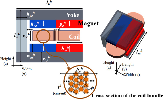
Design parameters of HVCM
Design parameters of HVCM
Figure 6 shows the design parameters of the HVCM. There are four independent parameters, three dependent parameters and six pre-defined parameters, which are dimensions of the coil, the magnets and the back-yokes. Descriptions of each parameter and the relationship among them are shown in Table 3 and Eqs (8)–(10).
Variation of design parameters of VCMs for sensitivity analyses

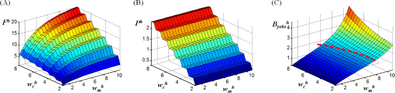
Results of sensitivity analysis of HVCM.
Figure 8 shows a general structure of a VCM with double sided magnet pairs. Generated force and ohmic loss are taken from Eq. (5) and Eq. (7). Equation (11) is a reduced form of Eq. (5) for the VCM of Fig. 8. The magnetic flux density, B, is dependent on the size of the magnet, c, and also the size of the coil, a and b, because the size of the coil determines the size of the air gap between the double sided magnet pairs.
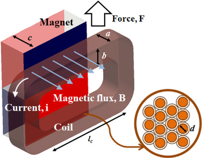
Typical structure of VCM. Magnets on one side are omitted for clarity of figure.
Design parameters of VVCM.
The number of the coil turns and the electric resistance of the coil can be easily obtained assuming that:
- Filling factor is nearly 1, i.e. coil winding is fully filled with coil wires and the thickness of the sheath is 10% of the diameter of the core.
- Electric resistance of the rounded part of a coil is negligible. The rounded part that is not used for force generation is very small compared to the effective part of the coil, as it should be for the VCM to be effective.
Then, the equations below are obtained [20].
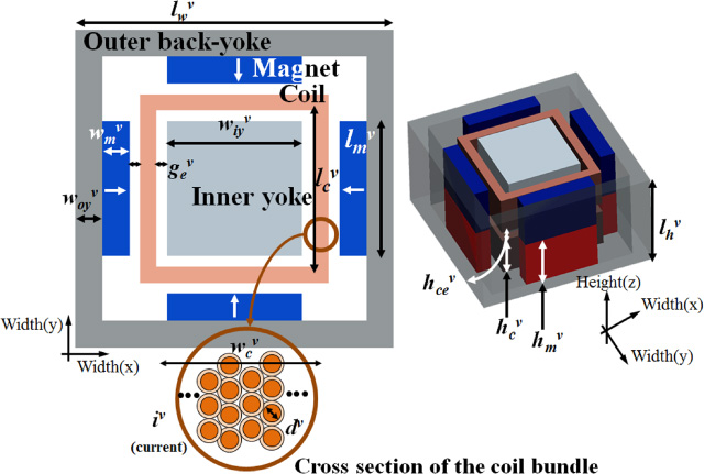
Figure 9 shows design parameters of the VVCM. There are four independent parameters, four dependent parameters and five pre-defined parameters, which are the dimensions of the coil, the magnets and the yokes. Descriptions of each parameter and the relationship among them are shown in Table 5 and Eqs (15)–(18).
Design parameters of VVCM

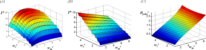
Results of sensitivity analysis of VVCM.
It is found again that the VCM cannot have high force and low ohmic loss at the same time. Thus, an optimization process is required. Most of the features are similar to those of the HVCM. Ohmic loss is more sensitive than force and magnetic flux density at yoke. Thus, related terms should be handled more carefully in the design and the manufacturing process. The discussion of the separation of the design parameter sets is also valid for the VVCM. The only difference is that the force has a maximal point with respect to the variation of the magnet size. Since the outermost size of the VVCM is fixed, increase of the magnet width causes decrease of the coil width and the coil length. This point should be considered in the optimization process.
HVCM
Objective and constraints
The objective of the optimization is to maximize the force of the HVCM. When the force is increased, problems of large ohmic loss and magnetic saturation are caused. These problems can be constrained through the design process. The objective and the constraints of the optimal design are presented in Table 6. Duty of 45% means that the HVCM is turned on during 45% of the total operation time. Based on the motion profile of the stage during the actual wafer fabrication process, the operation duty of the motor was determined. Therefore, the constraint of ohmic loss is also 45% of the ohmic loss when the HVCM is fully turned on.
Objective and constraints of optimization of VCMs
Objective and constraints of optimization of VCMs
It has been shown that the two sets of independent design parameters, “
In Section 3, a filling factor of 1 and a negligible rounded part of the coil were assumed for the simplicity. However, precise calculations of the number of coil turns of the HVCM, n
h
, and the electric resistance of the HVCM, R
h
, are given by Eqs (20) and (21).
Effect of design parameters

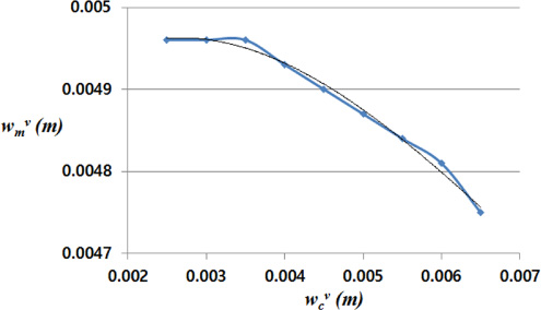
Relationship between design parameters
The results are presented in Table 7. There is no feasible solution for a diameter of coil wire larger than 0.7 mm. As expected, maximum forces are not much different for the variation of the diameter of the coil wire and the current, which means the assumptions about the coil in Section 3 and Eq. (14) are very reasonable. Even though the dimensions of the coil, the yokes and the magnets change, the maximum force of the HVCM within a confined volume barely changes. This means that an increase of the volume of the coil, the second term of Eq. (14), causes a decrease of the magnetic flux density, the last term of Eq. (14), and the two effects cancel out. This result provides a crucial lead for the beginning of the VCM design, which is accordingly a motion stage design process. The solution for 0.2 mm wire diameter shows the largest force but the terminal voltage, given by the voltage drop due to the electric resistance of the coil and the converted mechanical power [16], is more than 233 V, which is too high to afford with a typical power supply and a current amplifier. The solution with 0.6 mm coil diameter is chosen because it shows high force and moderate level of terminal voltage, 26.5 V. The final specifications of the designed HVCM are presented in Table 8. All the design parameters have been determined. Generated force larger than the required performance of 50 N is achieved with ohmic loss and magnetic flux density at the yoke smaller than the constraints.
Optimal solutions of HVCM with respect to discrete coil diameters
Final specifications of HVCM
Objective and constraints
The objective of the optimization is to maximize the force of the VVCM. The objective and the constraints are shown in Table 6, as for the HVCM, except for the constraint of ohmic loss. Since the stage is always levitated by the VVCMs, the duty of the VVCM is 100%.
Reduction of design parameters
In Section 2, it is described that the two sets of independent design parameters, “
Effect of design parameters
Relationship between design parameters
As in the case of the HVCM, the number of coil turns, n
v
, and the electric resistance, R
v
, are given by Eqs (23) and (24).
Optimal solutions of VVCM with respect to discrete coil diameters
Final specifications of VVCM
Finite element simulation
The force and the magnetic flux density at the yoke, from the optimized results, are verified by FE simulations before manufacturing. Ansys Maxwell V14.0 (Ansys, US) was used, and the comparison is shown in Table 11. It is shown that the design results are very similar to the simulation results, with the differences below 3.4%. As mentioned in Section 2, uniformity of the force constant is important. Force constant is acquired for each VCM when the magnet block moves from the nominal position 1.5 mm along the x, y and z axes simultaneously. The results shown in Table 12 indicate that both force constants are maintained within the motion range of the maglev stage. This feature leads to small uncertainty and easy control of the stage system.
Experimental evaluation
The manufactured VCMs and the test setup are shown in Fig. 15. The load cell (MAS-333-10L, CAS, Korea) is holding the magnet block of the VCM and the manual stage (B21-120C, Suruga Seiki Ltd., Japan) holding the coil winding aligns the magnet block and the coil winding. While slowly increasing the current input to the coil from zero to maximum value, the quasi-static force generated by the VCM is measured by the load cell. The signal from the loadcell is acquired by the DAQ device (DS2003, dSPACE GmbH, Germany). The increasing speed of current is 0.05 A/s, and the sampling frequency of data acquisition is 1 kHz. Figure 16 depicts the measured current-force relations of the VCMs. Both are perfectly linear. The slopes, i.e. the force constants, are presented in Table 13. The difference of the manufactured products and the optimal design results are lower than 3.4%.
Comparison of design results of VCMs with FE simulation
Comparison of design results of VCMs with FE simulation
Force constants of VCMs at acentric positions. The movers, magnets and yokes have been moved 1.5 mm in x, y and z directions at once
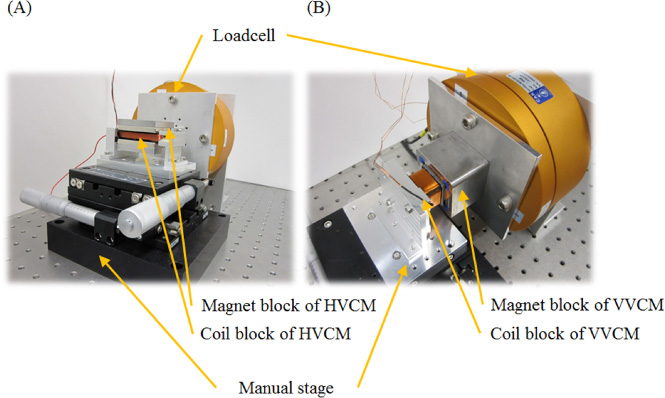
Experimental setups for VCM force evaluation. (A) HVCM. (B) VVCM.

Current force relation. (A) HVCM. (B) VVCM.
In order to compare the force capacity of the two developed VCMs, some quantified performance indices are introduced. The simplest way is calculation of the force constant per unit volume, because force can be increased with larger volume and higher current. However, this is meaningful only when the current can be provided without limitation. That condition is valid when the VCM is forced to cool, e.g. with water or air cooling or heat disposal through a heat duct directly connected to the coil. If the maximum current is limited by the safe temperature level of the materials, maximum force per unit volume is more meaningful. Those two performance indices are applied to the VCMs developed based on the experimental results. For the comparison, the duties were set to 100% for both types of VCMs. The maximum current for the second performance index of the HVCM is set to 2.31 A, which causes the same temperature increase as the VVCM. The comparison results are shown in Table 14. As expected, the VVCM shows about 10% higher force density due to the full use of the coil.
Force constant comparison of optimal design with manufactured ones
Force constant comparison of optimal design with manufactured ones
Comparison of VCMs using criteria introduced in this paper. Performance indices are obtained assuming full duty for both VCMs
In most cases of VCM design for industrial applications, not just for maglev stages, high force and small volume are strongly required. High force of an actuator is good for high speed and precision control of a motion system and small volume of an actuator is good for compatibility with the rest of the motion system. Therefore, the designer should in many cases consider designing a high force VCM within a confined volume. If the maximum allowable volume for the VCM is given, the structure of the VCM is determined considering mechanical assembly and wire connection. According to the volume and the structure, maximum power consumption, which is the same as the heat dissipation of the VCM, is determined to protect the components of the VCM from damage due to temperature increase. Then, a rough estimation of the maximum force capacity of the VCM can be calculated according to Eq. ((14)). Magnetic flux density at the air gap is typically about 0.3--0.4 T. This can be obtained in another way with the aid of a simple FE simulation. The estimation of the force at the early stage of the design process provides a chance to change the volume of the VCM or to add/change cooling equipment. Then, variations of the dimensions of the magnets and the coil are made to achieve the maximized force. The diameter of the coil wire and the current are determined considering the voltage drop. In the design process, uniformity is secured by extending the air gap in the direction of the motion. The air gap should be filled with uniform magnetic flux so that the VCM shows uniform characteristic even when the coil moves.
Conclusion
Through the design process of two different types of voice coil motors, a general design guideline for voice coil motors was suggested. Given the size and structure of the VCM, the maximum generated force is set to a certain level if there is no special cooling device. The rough estimation of maximum force provides the opportunity to change the structure of the VCM itself and the motion system at the early stage of the design process. It eliminates unnecessary design effort and time due to the wrong decision.
Two different types of voice coil motors are developed. One has the conventional and widely used structure, which generates high force with low aspect ratio. The other has the recently developed structure that generates high force with high aspect ratio. The latter showed approximately 10% higher force generation per unit volume, since it uses most part of the coil to generate force. In the design process of any motion system, the two types of VCMs can be chosen alternatively according to given space limitations.
Based on the developed mathematical models of the VCMs, the optimal designs were drawn in order to obtain maximized forces. Through the optimization process, the effects of the design parameters on the performance of the VCMs was inspected by parametric studies and mathematical analysis of the typical VCM structure. The optimized results were compared to FE simulations and the manufactured products. The small differences show that the modeling method was accurate. Those analyses provide insight into the VCM design process, which can be a guideline for designing any other types of VCM.
The presented design process considers most of the factors such as force, magnetic saturation, power consumption, terminal voltage, physical dimensions and so on. However, the method of assembly is not considered during the design process. The magnet block and the coil winding of the HVCM can slide horizontally with the clearance of the air gap. On the contrary, the magnet block and the coil winding of the VVCM can slide vertically with a clearance of the air gap. Thus, the assembly of the moving platform holding all the magnet blocks and the base frame holding all the coil windings are not simple. It is a feature of VCMs with iron yokes making a closed-loop of magnetic flux. When determining the structure of a VCM, it is required to consider manufacturability including the final assembly to a mother structure. The related study shall be our future work.
Footnotes
Acknowledgements
This work was supported by the National Research Foundation of Korea (NRF) grant funded by the Korea government (MSIT) (No. NRF-2019R1G1A1099736) and by a grant from R&D Program of the Korea Railroad Research Institute, Republic of Korea.