
Abstract
The lanthanum-doped lead zirconate titannate (PLZT) ceramic has shown its potential applications as light-controlled micro actuators activated by ultraviolet light for the photovoltaic effect in the field of micro-driven. Aiming to the slow response of photostriction of PLZT ceramic, the primary purpose of this article is to propose a light-controlled actuator with the novel opto-electrostatic hybrid driving based on PLZT ceramic. The mathematical model of the proposed light-controlled actuator is established on basis of the anomalous photovoltaic effect model of PLZT ceramic. The actuation characteristics of the micro actuator are investigated based on the established mathematical model and the experiments of the photovoltage of PLZT ceramic. Furthermore, the actuation curves of the micro actuator driven by opto-electrostatic hybrid driving based on PLZT ceramic are acquired to verify the rationality and feasibility of the light-controlled micro actuator design. So according to the analysis and experimental results, the light-controlled actuator driven by the novel opto-electrostatic hybrid driving based on PLZT can conduct the effectively and precisely displacement control with fast response speed. In addition, the driving method based on the novel opto-electrostatic hybrid driving has advantages of non-contact control, remote control and no electromagnetic interference, etc.
Introduction
As one kind of photostrictive material, lanthanum-doped lead zirconate titannate (PLZT) has exhibited its excellent properties and attracted attention extensively in the application of micro-driven as micro actuators. When PLZT ceramic is irradiated by ultraviolet light with a wavelength near 365 nm, a high photovoltage of several kV cm−1 is trigged because of the anomalous photovoltaic effect, and then the photo-induced deformation is generated due to the converse piezoelectric effect. Therefore, owning to the advantages of non-contact, light-controlled, remote control and no electromagnetic interference, PLZT ceramic has shown great potential application in the fields of MEMS (Micro-Electro-Mechanical System) and MOEMS (Micro-Opto-Electro-Mechanical Systems).
The photodeformation characteristic of PLZT ceramic makes PLZT ceramic have unique features in the field of micro actuator, and much research on the micro PLZT actuators has been investigated. Poosanaas et al. [1] investigated the photostrictive actuators. Morikawa et al. [2] proposed a new type of photoelectric motor due to the anomalous photovoltaic effect. Ichiki et al. [3] studied the electrical properties of PLZT in an electrostatic-optical motor application in. Shih and Tzou [4] investigated the discrete photostrictive actuators for photonic control of shallow spherical Shells. Yue et al. [5] designed new multi-DOF photostrictive actuator to improve multi-mode controllability of shell structures. Rahman and Nawaz [6] conducted the finite element modeling analysis of photostrictively driven optical actuators. Mahmoudpour et al. [7] designed and analyzed an innovative light tracking device based on opto-thermo-electromechanical actuators. Huang et al. [8] proposed an optically driven microgripper based on the photostrictive materials.
Being the foundation of the application of micro actuator, the photostrictive effect of PLZT ceramic has been applied to the shape and active control of various structures of beam, shell, plate, etc. Shih and Tzou et al. [9] studied the photonic control of shell based on PLZT ceramic. Sun and Tong [10] investigated the wireless vibration control of thin beams using photostrictive actuators. Jiang et al. [11,12] investigated the non-uniform control moments induced by a new photostrictive actuator, and then the vibration control of cylindrical shells with a hybrid photovoltaic/piezoelectric actuation mechanism was studied. He et al. [13,14] investigated the control of thin cylindrical shells laminated with photostrictive actuators. Wang et al. [15,16] carried out the closed-loop control for deflection of cantilever beam based on hybrid photovoltaic/piezoelectric actuation mechanism, and then the closed-loop photovoltage control of PLZT ceramic for photovoltaic-electrostatic driven servo system was conducted. So according to the previous work, PLZT has great prospects for development in the research area of active control.
Even though PLZT has shown great research potential in the area of micro-driven, however, the hysteresis phenomenon between the photo-induced deformation and the photovoltage has become the important factor restricting its research and development, which results in the slow actuation response of PLZT actuator directly using the photostrictive effect. And much research on the hysteresis phenomenon is investigated [17,18]. So aiming to the problem mentioned above, in this paper, a novel opto-electrostatic hybrid driving method based on PLZT ceramic is introduced and a micro actuator is designed based on this novel driving method. By the results of analysis, the fast response curves of the micro actuator are obtained. To this end, the opto-electrostatic hybrid driving proposed in this paper can cover the shortage of the slow response speed due to the hysteresis phenomenon.
Theoretical analysis of opto-electrostatic hybrid driving actuator
The anomalous photovoltaic effect
Under the illumination of ultraviolet light with a wavelength near 365 nm, the photo-generated carriers are generated and move along the direction of polarization of PLZT. Then a high photovoltage is generated rapidly between the two electrodes of PLZT because of the anomalous photovoltaic effect.
When the PLZT ceramic is illuminated by ultraviolet light, the photovoltage expression of PLZT ceramic can be obtained as [19]:
When the ultraviolet light is turned off, the comprehensive voltage after turning off the light source can be acquired as [15]:
According to the above-mentioned discussion, due to the anomalous photovoltaic effect, the PLZT ceramic can be used as an energy transducer for the light-controlled actuator. Figure 1 shows the light-controlled actuator driven by the novel opto-electrostatic hybrid driving based on PLZT. The driven component is connected to the PLZT through silver wire and conductive silver adhesives. The upper electrode is a clamped-free torsion structure, which is supported by two torsion beams. The necking structure is used as the connection part between upper electrode and torsion beam of the driven component, which can increase the length of the torsion arm without increasing the overall size. And according to the moment balance, the longer the torsion beam is, the greater the torsion angle is. So the output deformation is greater by taking the necking structure. The entire mechanism has a very high electrical conductivity. When UV is turned on, a large photovoltage is generated between the two electrodes of the PLZT and applied to the driving electrode, and then the generated electrostatic force due to the applied photovoltage will rotate the upper electrode at a certain displacement. Figure 2 shows the cross-sectional schematic diagram of the driven component. l, b, h are the length, width and thickness of the torsion beam; l 1, w 1 represent the length and width of the upper electrode, respectively; l 2, w 2 are defined as the length and width of the necking structure; d is the distance between the upper electrode and the lower electrode.
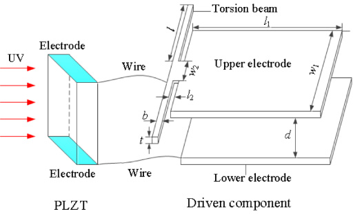
Schematic diagram of a light-controlled actuator driven by the novel opto-electrostatic hybrid driving based on PLZT.
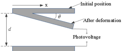
Cross-sectional schematic diagram of the driven component.
When the PLZT is illuminated by ultraviolet light, a large photovoltage U is applied between the upper and the lower electrodes. As shown in Fig. 2, the capacitance energy of electric field can be written as:
The electrostatic force between the two electrodes is:
The electrostatic force of infinitesimal section dx in the x direction can be written as:
The integral expression of the electrostatic moment can be obtained by integrating equation (5). In fact, the electrostatic moment generated of this structure consists of two parts:
Considering θ ≪1, sinθ ≈ θ, so the total electrostatic moment is written as:
Because the necking structure is used in this actuator, l
2 is designed to be small, which can be neglected in calculation, so the electrostatic moment can be reduced:
When the torsion angle of the torsion beam is θ, the recovery moment of the torsion beam is:
The electrostatic moment and the recovery moment of the torsion beam are balanced at a certain position. The balance condition is as follows:
From Eqs (9), (10) and (11), the relationship equation between the applied driven photovoltage and the torsion angle θ can be acquired:
According to above discussed, the simultaneous equations can be obtained as:
The torsion angle θ and torsion deformation S can be acquired by solving the simultaneous equations (13).
Due to the nonlinear effect of electric field force with distance change, when the applied voltage exceeds a critical value, this imbalance phenomenon (i.e. Pull-in phenomenon) will be occurred due to the two electrodes suddenly pull in. The maximum required driving voltage is the threshold voltage, also known as Pull-in voltage. And the torsion angle θmax generated at this time is the threshold angle, the equation of θmax is written as [20]:
Substituting the equation (14) into the equation (12), the threshold voltage can be written as:
According to the relevant references [21,22], the parameters of light-controlled actuator are determined and shown in Table 1.
The parameters and values of actuator
According to the equation (15) and the parameters in Table 1, the threshold voltage U max is 74.8 V.
PLZT specimens and experimental setup
As a kind of ceramic polycrystalline material, PLZT, which is composed of Pb(Zr,Ti)O3 doped with La and belongs to one solid solution. Due to its different compositions, dopant types and processing conditions etc, it has shown excellent characteristics with its ceramic polycrystalline. And its composition description can be represented as Pb1−x La x (Zr y Ti z )1−x∕4O3 or PLZT(X/Y/Z), where X = 100x, Y = 100y and Z = 100z. The PLZT (3/52/48) ceramics are taken as the specimens in our experiments, which are provided by Shanghai Institute of Ceramics, Chinese Academy of Science. The dimensions of the PLZT samples are 10 mm (length) × 5 mm (width) × 0.8 mm (thickness). The two electrodes of the PLZT sample are coated with Au, while they are connected by silver wires and conductive silver adhesives.
To investigate the relationship between the photovoltage and the displacement of the micro actuator, the experiments of photovoltage of the PLZT sample were carried out. Figure 3 shows the block diagram of the experimental set-up for testing photovoltage of PLZT sample. It can be shown that the ultraviolet light with a wavelength of 365 nm from the UV source is illuminated vertically to the upper surface of the PLZT sample, and then a photovoltage is generated between the two electrodes. Before irradiation, the UV source should be calibrated by the ultraviolet illuminometer at different intensities. And then the PLZT sample was applied several light intensities, i.e. 50 mW cm−2, 100 mW cm−2 and 200 mW cm−2.
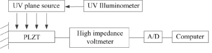
The block diagram of the experimental set-up for testing photovoltage of PLZT sample.
Figure 4 shows the photograph of experimental set-up. The ultraviolet light is generated by the UV probe with 40 mm × 40 mm illumination area. The irradiation time and the light intensity can be controlled by the intensity controller. The photovoltage can be measured by the high impedance voltmeter (Trek Model: 821HH), and the measurement range is 0 to ±2 kV DC while the accuracy is better than ±1% of full scale at the voltage monitor output.

The photograph of experimental set-up for testing photovoltage of PLZT sample. (1) PLZT sample, (2) Sensor head of the high impedance voltmeter, (3) Controller of high impedance voltmeter, (4) Computer, (5) UV source controller.
In the experiments, the irradiation time and the measurement time are set as 180 s. The time history of photovoltage under the irradiation of different intensities (i.e. 50 mW cm−2, 100 mW cm−2 and 200 mW cm−2) can be shown in Fig. 5.

Time history of voltage of PLZT under irradiation of different intensities.

The driving voltage of the PLZT sample under light intensity of 50 mW cm−2.
From Fig. 5, when the ultraviolet light is turned on, all the curves of photovoltage rise quickly and reach the maximum value directly. Moreover, the greater the light intensity, the shorter the time it takes to reach the maximum value. The curves will keep a steady state after they reach to the maximum point. So the greater the light intensity, the response speed of the actuator driven by photovoltage is faster.
When the irradiation begins, the photovoltage is generated and applied to the driven electrodes of the light-controlled micro actuator, and then the upper electrode starts to rotate down. Initial, the torsion deformation increases as the photovoltage increases. When the torsion deformation reaches to a certain threshold value S max, the driving voltage reaches the maximum value U max. At this time, S max is known as the snap-down deformation. Due to the snap-down phenomenon, when the driving photovoltage continues to increase, the deformation will beyond the certain threshold value S max, and the electrostatic torque balance will be broken, the upper electrode will touch the lower electrode.

The driving voltage of the PLZT sample under light intensity of 100 mW cm−2.
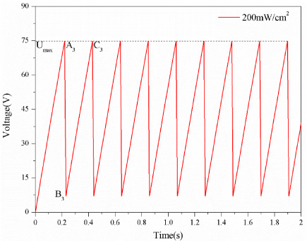
The driving voltage of the PLZT sample under light intensity of 200 mW cm−2.
Figures 6–8 show that the driving voltage of the PLZT sample under different light intensities; while Figs 9–11 indicate that the actuation curves of the light-controlled actuator under the action of driving voltage. It can be seen from figures that the upper electrode rotates quickly with the driving photovoltage increases when the PLZT sample is exposed to ultraviolet light. And the stronger the light intensity, the faster the response of the rotation of the upper electrode, the shorter the time it takes for the driving photovoltage to reach the maximum voltage and the snap-down phenomenon to occur. When the driving photovoltage reaches the maximum value U max at points A 1, A 2 and A 3 in the curves, the torsion deformation of micro actuator reaches the snap-down deformation S max. When the driving voltage increases over the maximum value U max, the upper electrode will touch the lower electrode duo to the snap-down phenomenon. As a result, because two driving electrodes contact each other, the photovoltage between the two ends of PLZT is neutralized, the upper electrode is restored under the action of the torsion beam recovery moment and finally reaches a steady state, the driving voltage at this time is called the lift-up voltage (Zhang et al. [20]), and the lift-up voltage is set as 7.2 V according to the relevant references, like B 1, B 2 and B 3 in the curves. However, the PLZT sample is exposed to ultraviolet light and the photovoltage continues to rises from the lift-up voltage to the maximum driving voltage U max quickly, so the upper electrode rotates from the steady state to the snap-down point again, just like C 1, C 2 and C 3, and then the snap-down phenomenon occurs once more.
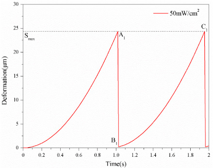
Actuation curve of the light-controlled actuator under light intensity of 50 mW cm−2.

Actuation curve of the light-controlled actuator under light intensity of 100 mW cm−2.

Actuation curve of the light-controlled actuator under light intensity of 200 mW cm−2.
From Figs 6–11, when the PLZT sample is illuminated by ultraviolet light, the driven component (i.e. the upper electrode) rotates from the steady state to the snap-down point repeatedly as the driving photovoltage increases form the lift-up voltage to the maximum voltage, and the stronger the light intensity, the process takes less time. It shows that the photovoltage of PLZT can effectively drive the electrostatic torsion structure to realize the opto-electrostatic hybrid driving micro actuator, and the novel opto-electrostatic hybrid driving method can completely make up for the lack of slow response due to the hysteresis phenomenon of PLZT. The next work is by optimizing the size of the rotation structure parameters or through effective control of the photovoltage, so the purpose of controlling the light source to effectively control rotation deformation can be achieved.
In this paper, a novel opto-electrostatic hybrid driving method based on PLZT ceramic is proposed to achieve fast response, which can make up for the disadvantage of slow response due to the hysteresis phenomenon. And the mathematical model of the proposed light-controlled actuator driven by the novel opto-electrostatic hybrid driving is established. The actuation characteristics of the micro actuator are investigated based on the mathematical model and experimental analysis. The analysis results show that the novel opto-electrostatic hybrid driving method not only has fast response speed, but also can control the rotation deformation of micro actuator effectively and accurately. Furthermore, the stronger the ultraviolet light, the faster the response speed. So it is believed that the novel opto-electrostatic hybrid driving method can significant improve the application of PLZT ceramic in the field of micro-driven.
Footnotes
Acknowledgements
The authors gratefully acknowledge the funding support from the National Natural Science Foundation of China (No. 51675282) and Jiangsu Overseas Visiting Scholar Program for University.