
Abstract
Sympathetic inrush current phenomenon occurs when a transformer is switched on in a power network containing other transformers that are already energized. This interaction significantly changes duration and magnitude of transient magnetizing currents in the transformers involved and may lead to misoperation of these equipment. Therefore, in this paper it is presented the results of electromagnetic analysis due to sympathetic inrush and inrush current phenomenon among single-phase 50 MVA transformers in a power substation in the northern region of Brazil. For this purpose, the nine single-phase transformers installed at SE Guamá forming three three-phase banks, were modeled in the ATP software to obtain the energization behavior. In this paper the electromagnetic analyzes are performed in steady state, so only the first peak is used. In this way, results of the electromagnetic behavior of transformers are presented and compared sympathetic inrush with inrush current.
Introduction
Transformer is one of the most important primary equipment and its stability and security have influence on the operational conditions of a power grid [1,2]. This equipment is submitted frequently to magnetizing inrush current, a phenomenon that occurs during energization of transformers connected to a power system network [3]. Therefore, the inrush current is a well-known transient phenomenon, which is caused by switching of a sinusoidal voltage source supplying an inductive load with ferromagnetic core such as a transformer or inductor [4–6].
Thus, some works have presented identification and restraining methods for inrush currents based on various mathematical principles as proposed in [2]. Nevertheless, these methods assumed that there was only one transformer in the power grid, ignoring the fact that there were always other transformers already connected. In fact, sympathetic interaction between transformers occurs when energizing a no-load transformer in parallel or in series with transformers already connected [7].
The sympathetic inrush may cause power quality problems such as voltage dips, that is temporary reduction of voltage magnitude at a point in the electrical system below a threshold [8]. This problem causes defects in transformers, amongst them are highlighted those which are produced by mechanical stresses due to power conditions when connected to electrical networks [4]. These mechanical stresses in the transformer’s winding are produce by transient electromagnetic simultaneous forces in the radial and axial directions.
In [9] a higher order statistic based method for discriminating the energizing current of an internal fault in transformers was presented. The transformer energizing can result in high differential current that may cause the differential relay to operate improperly.
In [10] was proposed an efficient numerical technique to compute transient electromagnetic force of a power transformer during three-phase short circuit condition. Thus, was analyzed the transient electromagnetic force action on every disk of transformer winding. However, was realized a simplified axi-symmetric model in transformer (analyzed in 2D simulations).
Differently, in this paper we propose an analyzed the transient electromagnetic force action on disks of transformer winding used a complete model in transformer (analyzed in 3D simulations).
Therefore, this paper accomplishes a modeling for single-phase transformer banks for electromagnetic analysis under inrush current and sympathetic inrush. The behaviors under these conditions were obtained from computer simulation ATP software, which is widely used for transient analysis problems [11]. Thus, this procedure was applied to nine single-phase 50 MVA power transformers forming three three-phase banks installed at the Eletronorte SE Guamá, in Belém City – PA – Brazil, which is a public utility concessionaire of electric power. For this, was realized accomplishes a modeling for single-phase transformer banks for electromagnetic analysis under sympathetic inrush phenomenon. It should be noted that a real geometry was used in the modeling of the transformer (considering the lamination characteristics of the core and the winding discs), which is different from the standard behavior presented by several researches. The worst conditions (higher peaks) for the inrush current and sympathetic inrush were used in the electromagnetic analysis.
Sympathetic inrush
The sympathetic inrush current phenomenon occurs when a transformer is switched on in a power system network containing other transformers which are already energized. Sympathetic interaction between transformers is a quite normal phenomenon in power systems. Some cases in the industry have shown that transformer energization inrush transient is not only dangerous because of its larger current magnitude, but also due to its rapid rate of rise [12]. Thus, when a transformer is frequently exposed to transients, it will deteriorate due to severe mechanical and thermal stresses and may eventually fail.
In recent years some works have been accomplished to identify the sympathetic inrush phenomenon to avoid the misoperation and internal faults in transformers. In [13] it was proposed a method based on decision tree rules for detecting inrush currents. In [2] it was used the mathematical morphology for identifying sympathetic inrush energization and internal faults in transformers.
The high inrush current may disturb or cause failure to operation of adjacent equipment in the circuit, for example, resulting in misoperation of power electronic converters and protection relays [14–16]. Moreover, sympathetic inrush may cause power quality problems such as voltage sags [8].
Therefore, it is important to carry out studies and analysis on transformers under sympathetic inrush. In [3] it was investigated the sympathetic inrush current phenomenon using nonlinear-transient field-circuit coupled with finite element formulation. For this, the cases of transformers connected in parallel and in series have been considered. The results were obtained for a 31.5 MVA three-phase transformer, which included the investigation of parameters affecting the magnitude and duration of sympathetic inrush phenomenon, such as series resistance, switching-on angle, residual flux density and load conditions.
In [17] it was presented as a case study the energization of a 510 MVA step-up transformer connected in a power plant. From this analysis, the results presented severe harmonic distortions and unbalanced currents, occurring the loss of several 6 kV motors and also blocking synchronous generators’ differential protection. This incident initiated an investigation of the associated transient phenomena and examination of possible ways to avoid similar events in the future.
Similarly, in [18] it was carried out a study in sympathetic inrush causes by re-application of voltage source to the transformer, which operates in parallel with two or more other transformers. For this, a modal approach to solving equivalent circuit by expressing differential equations in the state-equations form is selected. From the derivation of eigenvalues and eigenvectors, the phenomenon could be systematically investigated. Finally, simulation results were compared to captured Wide Area Monitoring System (WAMS) measurements of the phenomenon and reasons for discrepancies were discussed.
In [19] it was analyzed the influencing factors of sympathetic inrush through dynamic simulations tests. Finally, an identification method for sympathetic inrush based on the substation area information sharing was proposed. In [20] it was proposed a methodology able to identify sympathetic inrush conditions without the need to set a threshold, making the methodology intelligent to avoiding unwanted trip of the protection system. From tests, the proposed methodology has proved to be promising in the identification and discrimination between sympathetic inrush and internal faults.
In [4] electromagnetic analyses were performed on power transformers under the inrush condition. Nevertheless, this paper has the objective to present an electromagnetic modeling of the single-phase transformers under sympathetic inrush condition. Therefore, in order to facilitate understanding, the results of electromagnetic analyses of inrush and sympathetic inrush conditions will be compared.
Electromagnetic analysis
Inrush current
Studies have shown that the relevant factor for the maximum mechanical stress on transformer structures occurs during the first current peak. Unlike what happens in the short-circuit condition, when the exposure time to the fault occurs in tens of milliseconds, in the inrush condition the exposure time may last tens of seconds. Both currents can range from 6 to 8 times the transformer’s nominal current as in [21].
In a transformer, the inrush current first peak value can be calculated mathematically with the following development. First, it will be considered an applied sinusoidal voltage which is a function of a sinusoidal flux density and magnetization current with several peaks in its waveform, as presented in [21] and the calculation is based on the solution of Eq. ((1)).
Therefore, to determine mathematically the behavior of the power transformer inrush current over time, it can be used Eq. (3) [22].
Thus, if the ferromagnetic cores in transformers tend to saturate when the flux density
It has long been known that transient magnetizing inrush currents, sometimes reaching magnitudes as high as six to eight times the rated currents, can flow in transformers during their energization. However, it is observed that a transformer being switched on the system may provoke in other already energized transformers, transient magnetizing currents of an appreciable magnitude at the same time [21].
Thus, a transformer already connected to the system can experience unexpected saturation during the inrush transient of an incoming transformer. This saturation, which is established by an asymmetrical voltage drop across the system resistance caused by the inrush current in the incoming transformer, demands offset magnetizing currents of high magnitude in the already connected transformers. As show Fig. 1(a), when transformer T B is switched on to the network where transformers T A and T C are already feeding loads, the transient inrush currents no only flow through T B , but also through transformers T A and T C [3].

(a) Sympathetic inrush and (b) sympathetic inrush in series connection.
In general, it may be considered a series circuit of two transformers, T feeding T 1 as show in Fig. 1(b). When transformer T 1 is energized, transformer T experiences sympathetic inrush. Resistance between T and T 1 contributes mainly to the decay of the inrush current of T 1 and T [3]. Therefore, the sympathetic inrush current flows when multiple transformers are connected and one of the transformers is energized [24].
In Fig. 2 it is illustrated the single-line diagram of Guamá Substation that is responsible for supplying electric power to Belém City. This substation is composed of four (04) 230 kV transmission lines, three (03) 230 kV/ 69 kV and 150 MVA transformer banks and two (02) 55.5 MVAr capacitor banks --- with the purpose of keeping voltages at acceptable levels. Detailed information on this system can be obtained in [25].

Transformer banks modeling in ATP to obtain inrush current and sympathetic inrush.
For obtaining the sympathetic inrush and inrush current behavior of transformers, three three-phase banks of single-phase transformers were modeled in ATP software. Figure 2 shows the transformers banks modeling. In Fig. 3 is presented the simulation of inrush current with the case where the all switches (S A , S B and S C ) are previously opened and a transformer bank (Bank 01) is connected. Thus, the switch S A is closed at time t = 0.1 seconds. Thereby, the highest peak with value equal 1780 A, which will be used in electromagnetic simulation.
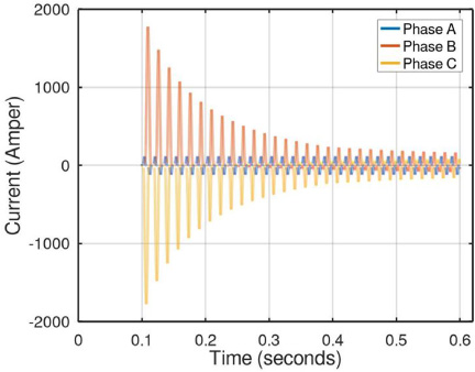
Waveform inrush current.
In Fig. 4 is presented the simulation of the case sympathetic inrush, switch SA was closed (connecting transformer bank 01 to the power system) while transformers connected by switches SB and SC (transformers bank 02 and bank 03) were already in operation. After closing switch S A (connecting transformer bank 01), the sympathetic inrush among transformers begins to occur in the connected transformers banks 02 and 03. Therefore, at time t = 0.1 seconds after switch S A was closed, the energization of bank 01 arises in transformer banks 02 and 03 magnetization currents, similar to inrush currents. Thereby, the highest peak this conditions is equal 569.6 A.

Waceform symphatetic inrush.
Transformers’ normal inrush currents decay, usually, within a few cycles, but the sympathetic inrush current persists in the circuit for a relatively longer duration [21]. In Fig. 3 it is illustrated the inrush current in an isolated transformer connected to the power system network and in Fig. 4 the sympathetic inrush current in the incoming and the already energized transformers.
It is emphasized that the energizing current changes with the impedance variation in the transformer winding. Thus, as impedance increases the duration of the energizing phenomenon also increases. However, for the study performed in this paper, only the first peak was be used in electromagnetics simulations (case the inrush current and sympathetic inrush).
Before installing a transformer in an electrical power system, the electromagnetic forces due to inrush currents must be predicted for secure operation. However, it is not easy to predict the electromagnetic forces accurately due to the complex structure of the transformer’s windings. The magnetic coupling of the windings in an actual transformer is imperfect. Therefore, a large magnetic flux field arises between the concentric windings if the transformer is under load. According to Ampere’s law, considering the quasi-static case, current in the transformer’s windings generates a magnetic field that is proportional to the current density [4–6], according to (5).
The electromagnetic forces in the transformers’ windings are generated by the interaction between the current density and the magnetic field density. These forces can be calculated according to (6).
The transient magnetic flux is the linkage flux and the leakage flux depends on the core magnetization characteristic. In a power transformer, the leakage flux density due to the inrush current increases significantly compared to the stationary operating state. The leakage flux is in the radial and axial directions. The components of the leakage flux are expressed using vector potential as in [4].
Initially to perform the analysis of electrical and magnetic performance, a 50 MVA single-phase power transformer with voltage ratios of (230/69/13.8) kV is considered. The transformer has concentric winding and the Low Voltage (LV) and High Voltage (HV) windings are of the disc type and the Tertiary winding (TERT) is of the helix type being connected in a three-phase bank.
For computer simulation implementation using FEM, it is necessary to know geometry and electrical and magnetic characteristics of the device. Therefore, it is illustrate in Table 1 the electric and magnetic characteristics of the power transformer under study [4].
Transformer’s characteristics
Transformer’s characteristics
Figure 5(a) shows representative points of the magnetization curve of the iron-magnetic alloy comprising the core of the analyzed transformer [4].

Magnetization curve of the transformer core.
In this paper, for the analysis developments proposed it were used two softwares, as shown in the Fig. 6. First, the software ATP was used for the behavior analysis of energization (inrush current and sympathetic inrush). Thereby, all peaks of the current during energization were defined. Thus, the highest peaks were used to electromagnetics analysis, the worst conditions.
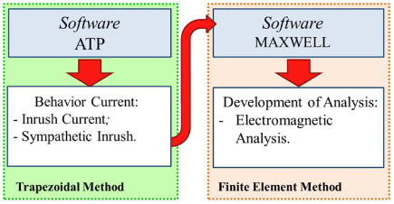
Presentation of flow chart used in the simulation.
Thereafter, the software ANSYS MAXWELL was used to analyze the behavior of dispersion magnetic flux density in winding and the electromagnetics forces action on every disk in transformer in 3D simulations.
In the electromagnetics simulations two conditions were analyzed: inrush current and sympathetic inrush. The main objective this paper is analyzes the behavior and severities of electromagnetics forces in the transformer’s winding energization.
Inrush current
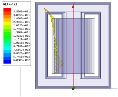
For the electromagnetic simulations in inrush conditions, initially it is used a current equal to 1780 A. The mechanical forces that will act on transformer’s winding depend on the dispersion magnetic flux density in the transformer’s winding. Thus, in Fig. 7 it is presented the magnetic flux density in the transformer’s winding.
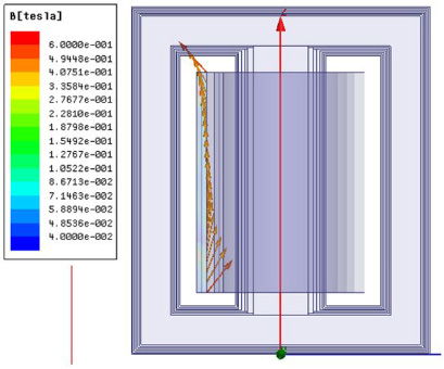
Magnetic flux density in transformer winding.
It can be observed in Fig. 7 the dispersion magnetic flux density in the transformer’s winding when in inrush condition. This effect occurs only in the HV winding [4]. Therefore, the dispersion magnetic flux density can achieve --- maximum value of 0.5 T, approximately.
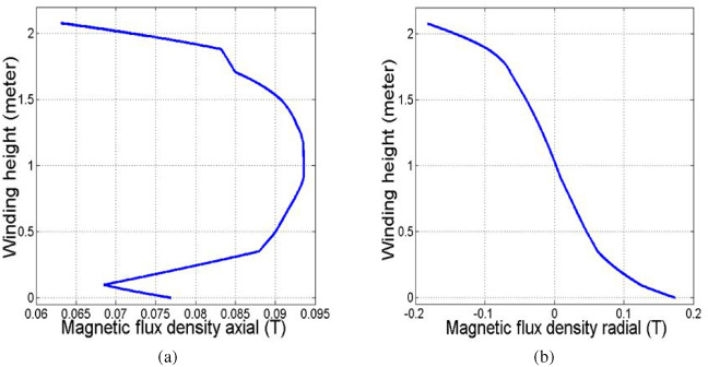
Thus, in order to better understand the axial and radial magnetic dispersion flux density behavior in the transformer’s winding, Fig. 8 presents separately in (a) the axial magnetic flux density in which the values are maximum at the center of winding (approximately 0.21 Teslas) and minimum at top and lower ends. In (b) the radial magnetic flux density in which the values are maximum at top and lower end (approximately 0.33 Teslas) and minimum at the center of winding.

Magnetic flux density in transformer’s winding (a) axial and (b) radial.
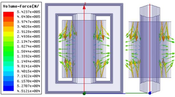
According to Eq. (8) the axial and radial forces in the transformer’s winding are derived from the product between the current density and the radial and axial magnetic flux density, respectively. The forces acting on the transformer’s winding is shown in Fig. 9, and it is possible to observe the maximum intensities at the end (compression forces) and minimum intensities at the center (hoop stress).
Resultant forces in transformer’s winding.
From this study, in Fig. 10 it is presented the axial and radial forces components from which, it can be analyzed the individual forces behaviors.
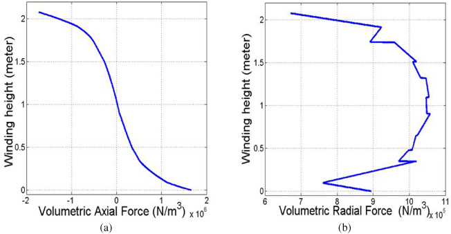
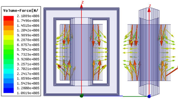
Components of volumetric forces in transformer’s winding (a) Axial and (b) Radial.
From results presented in Fig. 10 it can be observed that in (a) the volumetric axial force is minimum at center and maximum at top and lower ends (achieving a value of 1.72 × 10⁶ N∕m3). In (b) the volumetric radial force is maximum at center (achieving a value of 1.054 × 10⁶ N∕m3) and minimum at top and lower ends.
Likewise, as presented previously to inrush conditions, these analyses will be presented for sympathetic inrush condition it was used current value equal to 569.6 A. In Fig. 11 illustrates the magnetic flux density in transformer’s winding under sympathetic inrush condition. From this, it can be observed that the dispersion magnetic flux density can achieve maximum value of 0.26 T at winding top and lower ends.
Magnetic flux density in transformer’s winding in sympathetic inrush condition.
Figure 11 illustrates the axial and radial magnetic flux density behaviors in the transformer’s winding and Fig. 12 it is presented separately in (a) the axial magnetic flux density due to sympathetic inrush in which the values are maximum at the center of winding (approximately 0.094 Teslas) and minimum at top and lower ends. In (b) the radial magnetic flux density in which the values are maximum at top and lower ends (approximately 0.174 Teslas) and minimum at the center of winding.
Magnetic flux density (a) axial and (b) radial in transformer’s winding.
Therefore, the forces acting in the transformer’s windings are shown in Fig. 13 and it is possible to observe the maximum intensities at the end (compression forces) and minimum intensities at the center (hoop stress) for the sympathetic inrush condition.
Resultant forces in transformer’s winding in sympathetic inrush condition.
From this, in Fig. 14 is presented the components of axial and radial forces. Thus, it can be analyzed the individual forces behaviors.
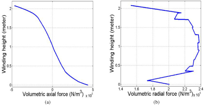
(a) Axial and (b) Radial components of the volumetric force in transformer’s winding s under sympathetic inrush condition.
In Fig. 14 it can be observed that in (a) the volumetric axial force is minimum at the winding center and maximum at the top and lower ends (achieving a value of 2.38 × 10⁵ N∕m3). In (b) the volumetric radial force is maximum at the winding center (achieving a value of 4.40 × 10⁵ N∕m3) and minimum at top and lower ends.
In Table 2 the results of axial and radial magnetic flux density for inrush and sympathetic inrush conditions are compared. From this, it can be observed that the values of axial and radial magnetic flux density under sympathetic inrush conditions are smaller than those due to inrush conditions.
Value obtained from magnetic flux density
Value obtained from magnetic flux density
Similarly, in Table 3 are presented the results of volumetric forces for inrush and sympathetic inrush conditions. From this, it can be observed that the values due to sympathetic inrush condition are smaller than those for inrush condition.
Value obtained from volumetric force
From Tables 2 and 3, it can be observed that under sympathetic inrush condition the values for magnetic flux density and volumetric force (axial and radial) presented smaller values when compared with values of inrush current. However, it be emphasized that the duration of sympathetic inrush phenomenon is longer that the inrush current. Thus, with the frequent occurrence this phenomenon, possible problems can damage the equipment.
In this paper, analyses and computer implementation were presented for 50 MVA single-phase transformers banks when subjected to sympathetic inrush and inrush current. 3D electromagnetic models were used to obtain simulation results. The inrush current occurs in a fraction of seconds during the transformer energization. However, the energization of a transformer connected to an electric network in the presence of other energized transformers, which are already in operation, leads to the phenomenon of sympathetic inrush current. However, it become emphasized the difficulty in discriminating in a transformer the high current amplitudes during the energization of an internal fault. Thus, when the protection doesn’t restrict properly the equipment can perform unscheduled shutdowns.
The equipment stop unplanned is related to costs to the company, both to maintenance and to not supplying electricity. Thus, in this paper it was presented the electromagnetic analysis in 3D simulations results comparing the inrush current and the sympathetic inrush current phenomena in 50 MVA single-phase transformers banks of a power substation in Belém City – PA, Brazil. For this, the ATP software was used to obtain the behaviors of inrush current and sympathetic inrush current (the highest current peaks were used, that is the worst energizing conditions were simulated). From these results, the commercial software based on the finite element method (FEM) was used to carry out electromagnetic analyses of these conditions.
Thus, it can be observed from the results of electromagnetic analyses presented in this work that inrush current presented biggest intensities of electromagnetics forces and magnetic flux density than for sympathetic inrush. However, in these results it can be observed that the inrush current decays in some cycles, while the sympathetic inrush persists for a relatively long duration. Therefore, it becomes important to perform analyses in transformers during all peaks their energization. Thereby, even the sympathetic inrush presenting lower severity and intensities of mechanical forces in the winding, they can be cause possible problems on this equipment with its occurrence frequently.