
Abstract
Composite materials have diverse engineering applications including the automotive, energy and aerospace industries. In manufacturing aircraft structures, the material is expected to endure atmospheric discharges. The present paper aims to model some of the effects of lightning strikes on a composite materials modeled through numerical simulation. The simulation is based on the finite-difference time-domain method which allows analysis the electromagnetic and thermal effects related to the problem. Aerospace standards are taken into account for modeling a lightning strike on a composite plate. The thermal distribution is evaluated based on results obtained from an electromagnetic simulation of the lightning strike effect. Since multiphysics problems are complex, the hypotheses adopted to obtain the results are also discussed. Results show the current density distribution on a carbon fiber reinforced plastic plate varying with the anisotropy characteristics of the material. From the thermal simulation it is shown that the lightning strike can cause a rise in the composite temperature over 900 °C with only 1 μs of interaction with the material.
Introduction
Carbon Fiber Composite (CFC) or Carbon Fiber Reinforced Plastic (CFRP) has been increasingly employed in engineering industries such as automotive and aerospace. By definition, a composite is a combination of two or more materials separated by a distinct interface that behaves as a single material with enhanced properties. The earliest known description of a carbon fiber application was in light bulbs in 1860 [1].
Currently, the main application lies in the aerospace sector that demands materials with high strength, high stiffness, high impact resistance, light weight, low thermal expansion and low damage under X-ray radiation [2]. For the aircraft industry, natural lightning is a major threat. It is estimated that each commercial aircraft is hit by lightning once every year on average [3]. In approximately 90% of the cases, the aircraft itself induces this phenomenon, the other 10%, the aircraft intercepts a lightning arc triggered naturally [4].
Atmospheric discharge is a natural disturbance where a significant amount of energy is released on a microsecond time scale. In turn, this phenomenon induces time-varying electric and magnetic fields [5] that can directly or indirectly damage the entire system. In both situations the system must meet its operational performance requirements [6]. Direct damage includes (but is not limited to) holes burned in the structure, fiber breakage, matrix cracking, delamination, thermal decomposition and vaporization of the resin [3] since CFRP materials possess a lower conductivity compared to metals. Indirect effects are related to electromagnetic compatibility (EMC) issues derived from a high current electromagnetic (EM) pulse with low frequency content.
While the latter is a purely electric phenomenon governed by Maxwell equations the former can be considered a multiphysics problem where electrical and mechanical laws have to be analyzed together. In numerical modeling a physical phenomenon under investigation is represented by a mathematical system which can be solved numerically [7].
Since CFRP possess low values of electrical and thermal conductivities they are more susceptible to lightning strike effects. The most important task in modeling lightning strikes in CFRP panels is the prediction of direct or indirect damage in the structure. As an alternative to the construction of real prototype models, this work considers the development of an electrical-thermal solver that will build and evaluate the early phase of a design to predict lightning effects in CFRP materials. Naturally, in performing an EM and thermal evaluation of CFRP struck by lightning, such a solver should yield data that any aircraft designer would have interest in.
Modeling method
State of the art
In order to better understand the lightning problem one may be interested in describing and visualizing the EM propagation in the CFRP. To do this one has to model the anisotropic material. The multiphysics problem starts with an electromagnetic phenomenon. Considering this, it is necessary to solve Maxwell’s equations in a given domain. There are two ways of solving the equations: analytical and/or numerical techniques.
Practical problems possess several difficulties or issues. This is the case for the lightning strike on composite laminates. The use of analytical formulas for the calculation of EM fields in a real CFRP is entirely impractical. Analytical methods seek to obtain an exact solution and in the form of a mathematical relation considering Maxwell’s equations for a given geometry.
CFRP modeling present complex geometries that are difficult to solve due to the need to satisfy the boundary conditions and the size of the constituent elements. In addition, this is a time-dependent problem within non homogeneous media.
On the other hand, the more details about the physical process the more the simulation will represent an actual lightning representation in this material. Nevertheless, in some cases, assumptions can be made to simplify the problem such as considering each layer an homogeneous material with defined tensor.
The finite-difference time-domain (FDTD) method is a scheme used to compute both electrical and thermal phenomena when lightning struck the CFRP. It is important to make clear that this problem could be solved with other methods such as the Method of Moments (MoM) and the Finite Element Method (FEM). FDTD and MoM are conceptually simpler and easier to program than the FEM, which is a more powerful and versatile numerical technique for handling problems involving complex geometries and non homogeneous media.
However, for the CFRP electro-thermal analyses purposes in time-domain the use of the FEM becomes prohibitive due to the number of degrees of freedom involved. One possible solution could be to switch to more advanced FEM strategies such as the Discontinuous Galerkin Method.
Research in the lightning strike effects on composite materials is increasing over the last decades. In [7] it was developed a methodology for predicting the impact of lightning on electrical equipment inside a composite aircraft in terms of electromagnetic interference. Two different commercial software have been used to implement the partial element equivalent circuit (PEEC) method and to conduct analysis in the time domain. The method developed by these authors was experimentally validated and allows one to evaluate, for instance, the impact on the on-board equipment when substituting a metal aircraft structure for a composite one. The actual effect cannot be verified by such method.
The ablation characteristics of CFRP material under lightning strike condition considering the thermal, electrical and structural effects coupled was studied in [3]. The lightning strike effect on the residual strength of the material was also evaluated. This work was based on a numerical method where the element suppression approach was employed. In this approach, the cell mesh is eliminated if its average temperature reaches the ablation temperature of the material, when that happens the boundary conditions and the mesh are rearranged. The results show that the lightning ablation effects are reduced if either the electrical conductivity or the specific heat of the material increases.
A numerical approach for modeling the plasma thermal behavior during the lightning strike on aircraft structures was conducted in [8]. This approach combines the finite element method, magnetohydrodynamics and the similitude theory, which allows reduces the computational cost by changing the scale of the problem. Only a fraction of the standards waveforms have been employed to evaluate the lightning strike effects.
The results show that the plasma over the structure can reach peak temperatures of the order of 40000 K. However, according to the authors, the main factor causing damage at the material’s surface is the electric resistivity not the plasma heat flux, since the interaction between the plasma and the structure is short. In addition, it was observed that the plasma pressure loading effect is negligible.
Many studies on this topic are related to experimentally evaluate lightning strike protection strategies for composite aircraft or find new ones. The investigation and comparison of two different protection methods applied to honeycomb sandwich structures composed of CFRP is discussed in [9]. The damaged area and depth show important differences according to the method employed.
Some of the main solutions used in the aerospace industry for protection against lightning and alternative solutions are summarized in [10]. In general, a metal screen made of aluminum or copper applied over the composite outer structure provides the protection against the direct effects of lightning. It can take the form of a foil, woven mesh or a non-woven mesh. Another solution mentioned by the authors are the use of a fabric that consists of a network of nickel coated carbon fibers. One can also find commercially available aluminized- E-glass structural fabric, which also provides electromagnetic shielding.
Advanced approaches consider the use of nano particles to provide the required electrical conductivity needed for the composite protection, for instance, one may use carbon nanotubes for that purpose. Such particles at certain concentration can substantially reduce the electrical resistance of the material.
The literature on numerical experiments to investigate the lightning strike effects on composite material is still scarce. Such methods are also important in the investigation of new protection solutions without the need for time consuming experimental analysis.
In addition, most of the numerical investigations developed neglect the multiphysics aspect of this phenomenon. In the present study, the purpose is to numerically investigate both the electromagnetic and thermal effects, where the dependence of the latter on the former is taken into account.
Material modeling
CFRP can be found in several configurations, with multiple layers and different forms. In addition, CFRP is composed of more than one material such as carbon fibers plus epoxy resin. The carbon fibers can be made with different orientations for each layer of the CFRP.
For all those reasons, modeling CFRP is a complex problem, basically because this is a heterogeneous material with random distribution. Heterogeneity imposes the calculation of boundary conditions between materials with different physical properties adding more operations to the simulations.
Another important issue is the anisotropy. CFRP presents significant changes in its physical properties due to its varied carbon fiber orientations. As a result, it is necessary to define thermal and electric conductivity tensors according to the CFRP characteristics.
As stated before, CFRP can possess random distribution of the carbon fiber. This affects whether or where the fibers are conducting electric or mechanic energy in its best configuration. However, considering electromagnetic interaction with frequencies below 1.5 GHz, a CFRP layer may be represented by a homogeneous model where effective materials properties can be used for both the matrix and the filler of the composite [11].
There are several models to predict the electric conductivity of CFRP. They include but are not limited to: statistical, thermodynamic, geometrical and structure-oriented models [12]. Each of the models consider different characteristics of a composite such as the manufacturing process and the molecular structure. While the models are useful for numerical evaluation and damage prediction, they have limitations and each addresses different CFRP attributes. Figure 1 shows some of the factors that may directly or indirectly influence the electrical conductivity in CFRP. For instance, the temperature directly influences the CFRP electrical conductivity while ionizing radiation affect it indirectly since it may cause a temperature variation in the CFRP.

CFRP electrical conductivity dependency.
For aircraft structures, the plies are stacked in such a sequence that provides the composite laminate quasi-isotropic properties. Different orientations of the fibers are observed along the laminate thickness. Accordingly, the change in properties for each layer should be considered in the model. For this study the composite plate was modeled considering the stacking sequence shown in Fig. 2.

CFRP stacking sequence adopted for this work.
For every layer, along the fibers’ direction both the electrical and thermal conductivity of the composite can be obtained from the multiplication of the fiber conductivity with its volume fraction since the composite matrix is nonconductive. Transverse to the fibers’ direction there are several methods to estimate the electrical conductivity, however most of them yield results which are not in agreement with experimental data. In any case, for this study physical properties values from previous studies involving similar topics to this one are considered. Then, for each layer the electrical and thermal conductivity tensors as a function of the conductivities in the main directions is expressed by ((1)) [13]:
The thermal and electrical conductivity values for the main directions used in this work are shown on Table 1.
Thermal and electrical conductivities values used in this work
It is possible to infer that the conductivities along the fiber direction are substantially higher than in other directions. For the electrical conductivities the values used in [15] were also considered, where the actual values of the composite used are 10000 S/m along the fiber, 2 S/m transverse to the fiber and 0.2 S/m through the thickness. Theses values were used when simulating the material with stacking sequence [90°∕0°]4s .
The specific heat of the composite material has significant influence on the thermal effects caused by lightning. The ablation damage decreases with increase in the specific heat [3]. In addition, the specific heat varies considerably with the temperature as can be seen on Table 2, so it is important to take this factor into account.
Density and specific heat of the composite AS/3501-6 as they vary with temperatue [16]
According to [3] the modifications from the original data allow better numerical stability. There is an abrupt change of the specific heat for temperatures ranging from 300 °C to 500 °C approximately. This occurs due to chemical reactions of the material and also because of the final sublimation phase of the epoxy. It is important to note that 3316 °C is the sublimation temperature of the composite laminate.
One may observe that the specific heat variation with the temperature behaves as a step function. Therefore to avoid numerical instability it was decided that the specific heat would be updated only if the temperature would change more than 1% from one iteration to another.
In anisotropic materials, the electric flux density is related to the permittivity tensor. In turn, the current density is related to the electric field by means of the conductivity tensor. This relation is described in (2):
In addition, considering non-magnetic materials, Faraday’s law can be written as shown in (3):
The FDTD method is used for the computation of both the electromagnetic field and thermal distribution in the CFRP plate. The update procedure adopted for the electromagnetic field is the one described in [13]. The authors derived an extension of the FDTD equations, proposed by Yee, to evaluate the electrical and magnetic fields in an anisotropic material. The equations written in matrix form are shown in Eq. (4) [13]:
In the original Yee algorithm, E and H-fields are half cell apart. However in Eq. (4) they appear at the same location. In order to calculate the propagation in anisotropic materials the E and H fields must be interpolated.
When an electric current flows through a solid or liquid of finite conductivity, the electric energy is converted to heat through resistive losses in the material, this is expressed by (5), which represents the Joule effect and gives the temperature as a function of the thermal properties of the composite laminate, the current density and the electric field generated from the lightning strike.
The energy losses can assume the forms: (i) Convective flux of heat or mass; (ii) Radiative flux of heat; (iii) Pyrolysis gas formation. Convective flux is taken into account using (6):
The radiation heat transfer can be calculated using (7) :
The heat loss by the pyrolysis gas formation is not accounted for in this work.
The term J ⋅ E represents the Joule effect which is obtained from simulation of the electromagnetic field distribution on the CFRP plate. In other words, the heat source for thermal distribution analysis is an output parameter from the electromagnetic simulation. Each mesh point has a correspondent Joule effect value. The current density can be calculated using (8) [17] :
For the temperature update the term J ⋅ E is seen as a constant value, once they are obtained previously from the electromagnetic simulation.
Equation (5) is discretized using the central difference approach for the spatial derivatives and backwards difference approach for the time derivative. Therefore the update equation for temperature is seen as an implicit scheme, with the update of temperature dependent on the neighboring temperature values in a same time step n. The discretized temperature update equation is shown in (9):
Energy losses by convection and radiation are not shown in (9) because they are only considered on the composite’s surface. To take thermal losses into account, an analogy to electrical resistance has been made, where the energy loss is computed as thermal energy flux calculated from a thermal resistance approach.
The mesh point was considered in the middle of each cell, therefore the surface temperature was not available for computing the radiation loss. In this case, the temperature of the surface was approximated as being equal to the temperature in the center of the closest mesh cell.
Interest in modeling lightning strikes in aircraft has increased over the years. This is due to the fact that lightning is a complex phenomena that deserves intense research for the conception of preventive countermeasures. Lightning can be defined as the energy transfer between a thundercloud and ground or the movement of charges from cloud to ground (or vice-versa). The aircraft can change the charge balance in the cloud triggering lightning [18].
As stated before, describing the whole phenomenon is a complex task since lightning changes the matter during its energy transfer. In our EM model of CFRP, lightning strike was used as a waveform available in the standard ARP5412 from the Society of Automotive Engineering (SAE), represented in Fig. 3.

Lightning waveform [19].
The Lightning waveform contains four components, A to D. Equation (10) defines the component A for the lightning current discharge. This is the source of the EM FDTD model used to determine the electric fields and the current density in the CFRP. As a consequence, those intensities are used to calculate the temperature in the composite plate model.
To evaluate the lightning strike effects an injection and an extraction point of the current in the composite plate model are determined. The plate surrounded by air, whose characteristics are based on the work done in [15].
The CFRP panel has 16 layers with the stacking sequence [45°∕90°∕ −45°∕0°]2s and dimensions of 300 mm × 300 mm. The actual thickness of each composite layer is 0.2 mm. The air surrounding the composite plate occupies a volume of 600 mm × 600 mm × 200 mm.
The entire domain was discretized using rectangular-prism cells with dimensions of 10 mm for both the x and y directions and 2 mm for the z direction. A time-step of 6.36 ps was used. The current injection and extraction were applied in the third outermost mesh cells representing the composite in the x direction, centered in the y direction. The configuration model used for the simulations is shown in Fig. 4. A perfect conducting wire is used to connect the injection and extraction points from the top layer to the bottom layer.

Simulation model for evaluating the lightning strike effects on a composite plate.
For the electromagnetic simulations, the second-order Higdon absorbing boundary condition was employed [20]. For the thermal simulations, only the CFRP panel was modeled. In this case, the radiation and convection losses were considered as boundary conditions on the material surface.
Several reasons lead to some simplifications in analysis of the problem such as computational cost and the high complexity for implementing some of the lightning strike characteristics. The hypotheses taken into account are shown below:
Simplification of the phenomenon: the plasma physics concerning this subject was not considered. The plasma generated from the lightning strike on composite aircraft was not considered in the simulations due to the complexity in its representation. Although the plasma temperature over the aircraft may reach substantial values, the interaction time between the plasma and the aircraft structure is extremely short [8]; The current is applied at a single mesh point. For this work, the current was injected and extracted at single mesh points, however it is understood that in an actual situation the current will cover a larger area. Furthermore, the current was excited directly on the composite material, the lightning channel was not modeled. To model it considering its actual dimensions or a considerable part of it would significantly increase the computation cost; Static excitation of the electrical current. Since aircraft tend to fly more than their own length during the lightning occurrence, the electric arc will move from its initial incidence point reattaching to other spots [21]. However, in this work the current excitation was considered in a static spot; Uncoupled thermal and electromagnetic effects. As a result of the substantial difference in time scale for the evaluation of the thermal and electromagnetic effects, the coupling characteristics existing between these two effects were not considered; Constant thermal conductivity. The thermal conductivity has no significant influence on the lightning strike effects [3], this work verified that the maximum temperature on the composite do not change with the thermal conductivity variation; Constant electrical conductivity. For the lightning strike phenomenon the temperature rise is the main factor that may influence the variation of electrical conductivity. However since the thermal and electromagnetic effects are not coupled, the electrical conductivity variation is not taken into account; Composite relative permittivity equal to 1. Not much information is openly available for CFRP with the characteristics considered in this work, for that reason the composite relative permittivity was assumed to be 1. This hypothesis was based on the study done in [15], who used this same value in their simulations and had experimentally validated the results obtained from them; Composite thickness ten times larger than it’s actual value. The maximum time-step value for the FDTD method used in this work is limited by the smallest mesh cell, as specified by the Courant-Friedrichs-Lewy (CFL) stability condition [22]. The layers of composite material are very thin. Their thickness in the simulation was taken ten times larger than their actual value. This approach allowed a substantial reduction in computational cost. Some of the material’s electrical conductivities were proportionally modified to compensate for the increase in thickness. This same strategy was also applied in [15] and [23].
Numerical validation
Electromagnetic numerical validation
The code developed for the electromagnetic simulation was validated by means of performance evaluation of a microstrip patch antenna deposited on an anisotropic dielectric substrate. Although this is a different problem, the update equations of the electromagnetic field components and the boundary conditions are exactly the same for both problems. In the present work the scattering S-parameter was analyzed, which is obtained from the ratio between the transmitted and reflected pulses at the circuit port over the incident pulse. The data is provided in the time domain by FDTD and later transformed to the frequency domain.
The operating resonant frequencies are evaluated from S-parameter computation, the results obtained from this analysis are shown in Table 3 along with the relative error from the comparison made with the results found in [24].
Performance evaluation of a microstrip patch antenna deposited on anisotropic substrate
Performance evaluation of a microstrip patch antenna deposited on anisotropic substrate
One may observe that the relative errors obtained from the results were below 1% for the three anisotropy angles analyzed, in some cases the exact resonance frequency value was obtained. The second order Higdon absorbing boundary condition was used, a highly efficient absorbing boundary condition such as the perfectly matched layers (PML) could have provided more accurate results. Furthermore, not all neighboring fields are available for the electrical field components updating on the boundaries of the model. In these conditions the same update equations used for isotropic materials was adopted. That is not a problem for the lightning strike simulation model because its boundaries are in air, which can be updated using the equations for isotropic media.
The performance of an antenna printed on isotropic substrate was also analyzed. The results were in agreement with the experimental data obtained from [25].
For the thermal simulation a code capable of evaluating the thermal distribution in isotropic media for application in a three-dimensional model was developed. Thus, a prescribed temperature condition was employed on four lateral faces of a plate model and adiabatic condition on the bottom and upper surfaces. With this, it was possible to validate the code comparing the results with an analytical solution of a two-dimensional problem. Figure 5 shows the lateral boundary conditions and the temperature distribution obtained from that.

(a) Boundary conditions and (b) temperature distribution.
From Fig. 5, it can be seen that on one of the faces the temperature varies along the plate length. It follows the function shown in (11) :
The numerical result for the temperature in the middle of the plate is obtained for different mesh dimensions as shown in Table 4.
Temperature in the middle of the plate obtained from a mesh refinement analysis
where n x , n y and n z represent the number of mesh nodes in the x, y and z directions.
One may see that as the mesh gets more refined the numerical result gets closer to the analytical result. Therefore, observing this convergence the code has been considered validated, and it was enhanced to allow anisotropic media application.
Modeling the material with the stacking sequence [45°∕90°∕ −45°∕0°]2s would produce unrealistic current density magnitudes when applying the interpolations to take into account the actual position of the fields on the Yee cell. Considering the characteristics adopted for the model, it was observed that when the interpolations are taken into account, the current can not flow in the fiber direction when they are oriented at 45° and −45°.
Therefore, only the angles 0° and 90° were considered when using the interpolations. A current of amplitude 3 kA was injected in a composite material with stacking sequence [90°∕0°]4s . The current density distribution at 6.4 μs is shown in Fig. 6.

Current density distribution for the first two layers of a composite plate. First layer with fibers oriented in 90° (a); second layers with fibers oriented in 0° (b).
From Fig. 6 one may observe that the current density concentrates along the fiber direction as expected. The electrical conductivity of CFRP materials on fibers direction are substantially larger than in other directions. Considering the interpolations mentioned earlier, it was observed that the current would not flow along the fibers for angles different than 0° and 90°. For that reason the current would concentrate on it’s excitation point resulting in too high values for the current density. The range values observed in Fig. 6 are in agreement with the published data [15].
Removing the interpolations to consider the fields on their actual location in the Yee cell, it was possible to evaluate the lightning strike effects on a composite with the stacking sequence [45°∕90°∕ −45°∕0°]2s . For that a current of amplitude 200 kA magnitude was considered. The current density distributions at 1 μs for the first four layers and along the plate thickness are shown in Fig. 7 and Fig. 8, respectively.

Current density distribution for the first four layers of a composite plate: 45° (a), 90° (b), −45° (c) e 0° (d).

Current density distribution along the CFRP plate thickness at the current injection point.
From Fig. 7 one may observe the current flowing along the fiber orientation as expected. Although only rectangular prism cells were employed, in terms of the current density distribution pattern, the results are similar to [15] when using triangular prism cells. The layer with fibers oriented at 45° is an exception as it is more similar to the results obtained in [15] when using rectangular-prism cells.
Figure 8 shows that the current concentrates on the first layers of the composite, around the injection and extraction points of the source where the current density values are relatively high on the first layers and drastically decrease towards the inner layers. This result shows consistency with published experimental data, for example in the work done by [26], where it has been noticed from experimental observation that electrical discharges, with peak current of 80 kA would damage only the outermost layers of a CFRP panel.
The ohmic heating effect was evaluated considering the results obtained from the electromagnetic simulation. First, a mesh refinement analysis was conducted, the mesh dimensions taken into account are shown in Table 5 and the results of this analysis are presented in Fig. 9.
Meshes dimensions taken into consideration on the mesh refinement analysis
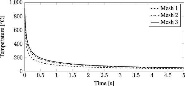
Mesh refinement analysis.
Figure 9 shows the temperature evolution of the mesh point with highest initial temperature value. Only the first five seconds right after the lightning strike interaction with the CFRP plate were considered.
It can be observed that there is not much accuracy gain going from mesh 2 to mesh 3, on the other hand computational cost increases considerably. The highest difference between meshes 2 and 3 was 5.50%, but for most part of the time it was bellow 2.00%. Therefore, mesh 2 has been chosen for use in further analysis. On the thermal simulations the time increment was set to 1 ms.
Two temperature profiles that intersect the mesh point with the highest temperature value were analyzed at different moments. The results are shown in Fig. 10 and Fig. 11.
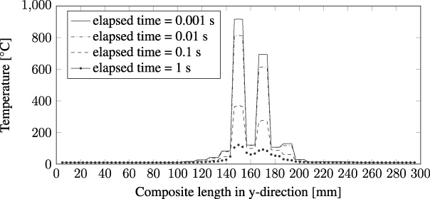
Temperature profile along y-axis.
Figure 10 represents the temperature profile along the y-axis for a horizontal line plotted at the mesh point with the highest temperature which can be observed in Fig. 14(a). The temperature profile is in agreement with the heat source profile for the same region, shown in Fig. 12. As mentioned earlier, the heat source results from the electromagnetic simulation.
Similarly, Fig. 11 represents the temperature profile along the x-axis for a vertical line plotted at the mesh point with the highest temperature which can be observed in Fig. 14 (a). This temperature profile is also in agreement with the heat source profile for the same region as shown in Fig. 13.
Examining the plots from Fig. 9 to Fig. 11, one may see that the heat generated by the lightning strike is rapidly dissipated. Furthermore, the heat seems not to be absorbed by the neighboring cells. Such behavior may be explained by the following aspects of the model: the lightning strike source is employed at a single mesh point and with a short time interaction with the composite plate, so that the energy from the lightning strike is concentrated in a single mesh cell, making it easy to dissipate; the composite material has low thermal conductivity values; the highest temperature point lies on the external layer where radiation and convection losses are taken into account, which may have caused the rapidly absorption of the generated heat.

Temperature profile along x-axis.
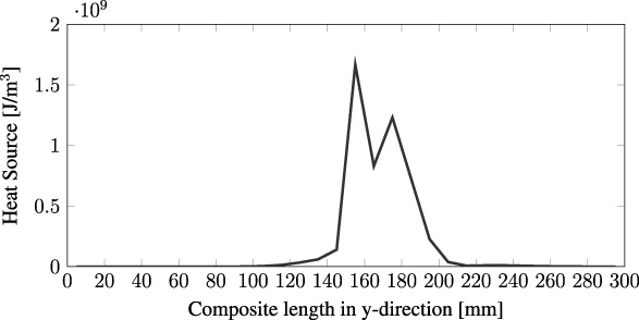
Heat source profile along y-axis.
A small difference is noticed between the temperature and heat source profiles since the mesh is more refined in the thermal simulations.
The room temperature was set to 10 °C the same value was used for the initial temperature of the CFRP plate. The maximum temperature value obtained from the simulation was approximately 920 °C. The temperature distribution on the first four layers of the composite, after 0.01 seconds, are shown in Fig. 14.
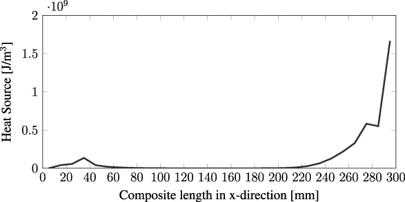
Heat source profile along x-axis.
From Fig. 14, one may notice a substantial temperature difference among the layers. Moreover, it is noticeable that the lightning strike effect behaved in a punctual manner.
The thermal effect considering the lightning strike current with peak value of 3 kA using the same CFRP panel model with stacking sequence [45°∕90°∕ −45°∕0°]2s . The maximum temperature value for three different interaction times between the lightning strike and the composite material were obtained, the results are shown in Table 6.
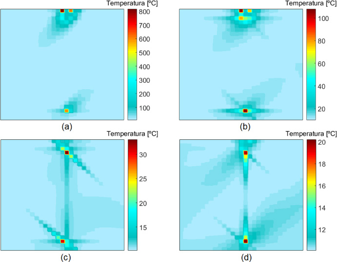
Temperature distribution on the first four layers of the CFRP plate: 45° (a), 90° (b), −45° (c) e 0° (d).
Results obtained from lightning strike simulation with current peak of 3 kA
The temperature increases considerably with the rising of interaction time between the lightning strike and the CFRP plate. According to SAE ARP5412 standard, the component A of the lightning strike current waveform can last up to 500 μs. Therefore, one may see that the temperature of the composite can easily reach relatively high values. However, in the simulation model the lightning current is employed at a single mesh cell, in an actual situation it would most likely cover a larger area, so the ohmic heating effect would not be concentrated in a single point.
The lightning strike itself is a complex phenomenon to model. Although some significant simplifications were made about it’s physics, the anisotropic characteristics of the composite materials still present some challenging aspects when evaluating this phenomenon.
Understanding the physics of this matter, one may see that the temperature is the most important factor that may affect the thermal and electrical conductivities variations. However, this variation is not taken into account. As mentioned earlier, to employ the electrical conductivity variation with the temperature, the thermal and electromagnetic coupling would be needed. However, they have substantial differences in time constant between each other, so the hypothesis of a weak coupling has been adopted.
About the thermal conductivity variation with the temperature, it was observed that it does not change the maximum temperature the material will reach with the lightning strike since this phenomenon happens too fast and with the relatively low thermal conductivities values, during the occurrence of the lightning strike the material is not able to dissipate a significant amount of the heat received.
The electrical current distributions are in agreement with the anisotropic characteristics of the CFRP plate. Although this distribution is in agreement with the literature as well and the update equations were validated with a different problem from another source the experimental validation of the problem considering the thermal effects is still important, which will be done in a future work.
The thermal effects concentrated close to the application point of the current source are also congruent with published data. Relatively high temperature values may be observed due to the lightning strike on composite materials, even though only 1 μs of interaction time of the 200 kA peak current with the CFRP panel was simulated, the composite could reach a temperature higher than 900 °C. In an actual scenario the current would be distributed in a larger area, on the other hand, a longer interaction time would be observed.
The multiphysics model developed for this work was capable of providing information about the lightning strike effects on a CFRP plate, where the current density and the thermal distribution were obtained from separated simulations. The results are consistent with the literature, however, it is important to observe theses effects considering the electromagnetic-thermal coupling in a future work. This model allows the thermal gradient and the electromagnetic analyses in anisotropic materials, a still scarce literature on this matter.
As for the FDTD method applied in this study for the electromagnetic field update, to evaluate the problem in more detail such as to considering the entire current waveform, it yields a relatively high computational cost. There are other methods that may overcome this problem. For instance, one could use the Alternating-Direction Implicit FDTD method, which was developed in [27] and does not require that the CFL criterion be satisfied.
The present work also highlights the importance of characterization of composite materials used in the aviation industry. Not much information is available in literature, in addition they tend to be incomplete, and are not covering all the aspects needed for a proper evaluation of lightning strikes on CFRP materials. For example, in a general manner the variations in properties over a temperature range that are observed in this kind of study are not taken into account.
Lastly, although the motivation of this work focused on the aerospace field, it is known that this topic has other applications. Wind turbines and automotive industries may also benefit from this work.